

Page 1
USER
MANUAL
MODEL 2703-X21
G.703/E1 Digital Modem
SALES OFFICE
(301) 975-1000
TECHNICAL SUPPORT
(301) 975-1007
http://www.patton.com
Part# 07M2703-X21-C
Doc# 031111UC
Revised 6/19/98
CERTIFIED
An ISO-9001
Certified Company
Page 2

1.0 WARRANTY INFORMATION
Patton Electronics warrants all Model 2703-X21 components to
be free from defects, and will—at our option—repair or replace the
product should it fail within one year from the first date of shipment.
This warranty is limited to defects in workmanship or materials, and
does not cover customer damage, abuse or unauthorized modification.
If this product fails or does not perform as warranted, your sole
recourse shall be repair or replacement as described above. Under no
condition shall Patton Electronics be liable for any damages incurred
by the use of this product. These damages include, but are not limited
to, the following: lost profits, lost savings and incidental or
consequential damages arising from the use of or inability to use this
product. Patton Electronics specifically disclaims all other warranties,
expressed or implied, and the installation or use of this product shall be
deemed an acceptance of these terms by the user.
1.1 RADIO AND TV INTERFERENCE
The Model 2703-X21 generates and uses radio frequency energy,
and if not installed and used properly—that is, in strict accordance with
the manufacturer's instructions—may cause interference to radio and
television reception. The Model 2703-X21 has been tested and found
to comply with the limits for a Class A computing device in accordance
with the specifications in Subpart J of Part 15 of FCC rules, which are
designed to provide reasonable protection from such interference in a
commercial installation. However, there is no guarantee that
interference will not occur in a particular installation. If the Model 2703X21 does cause interference to radio or television reception, which can
be determined by disconnecting the unit, the user is encouraged to try
to correct the interference by one or more of the following measures:
moving the computing equipment away from the receiver, re-orienting
the receiving antenna and/or plugging the receiving equipment into a
different AC outlet (such that the computing equipment and receiver are
on different branches).
1.2 SERVICE
All warranty and non-warranty repairs must be returned freight
prepaid and insured to Patton Electronics. All returns must have a
Return Materials Authorization number on the outside of the shipping
container. This number may be obtained from Patton Electronics
Technical Service at (301) 975-1007.
Packages received without an
RMA number will not be accepted.
Patton Electronics' technical staff is also available to answer any
questions that might arise concerning the installation or use of your
Model 2703-X21. Technical Service hours: 8AM to 5PM EST, Monday
through Friday.
1
2.0 GENERAL INFORMATION
Thank you for your purchase of this Patton Electronics product.
This product has been thoroughly inspected and tested and is
warranted for One Year parts and labor. If any questions or problems
arise during installation or use of this product, please do not hesitate to
contact Patton Electronics Technical Support at (301) 975-1007.
2.1 FEATURES
• Synchronous network data rate of 2.048 Mbps
• Four selectable terminal rates: 256 kbps, 512 kbps,
1.024 Mbps and 2.048 Mbps
• Supports X.21 terminal interfaces on a DB-15 connector
• Both 75 ohm (BNC) and 120 ohm (modular) network terminations
• Selectable Internal (master) or Network (slave) clocking
• Loopback test modes
• Front panel LED indicators for power, network,
master clock and test loop
2.2 DESCRIPTION
The Patton Model 2703-X21 G.703/E1 Access Converter wears
several hats: As an
access product
, the Model 2703-X21 receives
unstructured, synchronous 2.048 Mbps data from a G.703 network and
sends it to a router, bridge, multiplexer or other device. As an
interface
converter
, the Model 2703-X21 accepts 120 Ohm twisted pair or 75
Ohm dual coax network connections (both types of interfaces
provided). Then it converts the signals to an X.21 format on a DB-15
connector.
As a
Rate Adapter
, the Model 2703-X21 lets a lower bandwidth
device–256 kbps, 512 kbps, or 1.024 Mbps–connect to a 2.048 Mbps
G.703 link. The Model 2703-X21 supports Internal (master) or Network
(slave) clocking. Loopback test is built-in, and front panel LEDs monitor
power, network, master clock and test loop. Several power supply
options are available.
2
Page 3
Switch Set S1
The configuration switches on S1 set clocking, rate adaptation,
loopback enable, and data invert. The default settings are
summarized in the table below.
S1-1: Master/Slave Clock
The setting for switch S1-1 determines whether the Model 2703X21 provides the master clock, or is slaved to another clock source.
S1-1
Setting
On Model 2703-X21 is master
Off Model 2703-X21 is slave, (clock is recovered
from the network)
3.0 CONFIGURATION
The Model 2703-X21 is equipped with one DIP set containing eight
switches (externally accessible), as well as seven jumpers (internal).
These switches and jumpers allow configuration of clocking, data rate,
and test options. The Model 2703-X21 is also equipped with an internal
switch that allows selection of 115 or 230 VAC power inputs (Note: this
switch is not present in Models 2703-X21-UI and 2703-X21-DC). This
section describes switch and jumper locations and explains all possible
configurations.
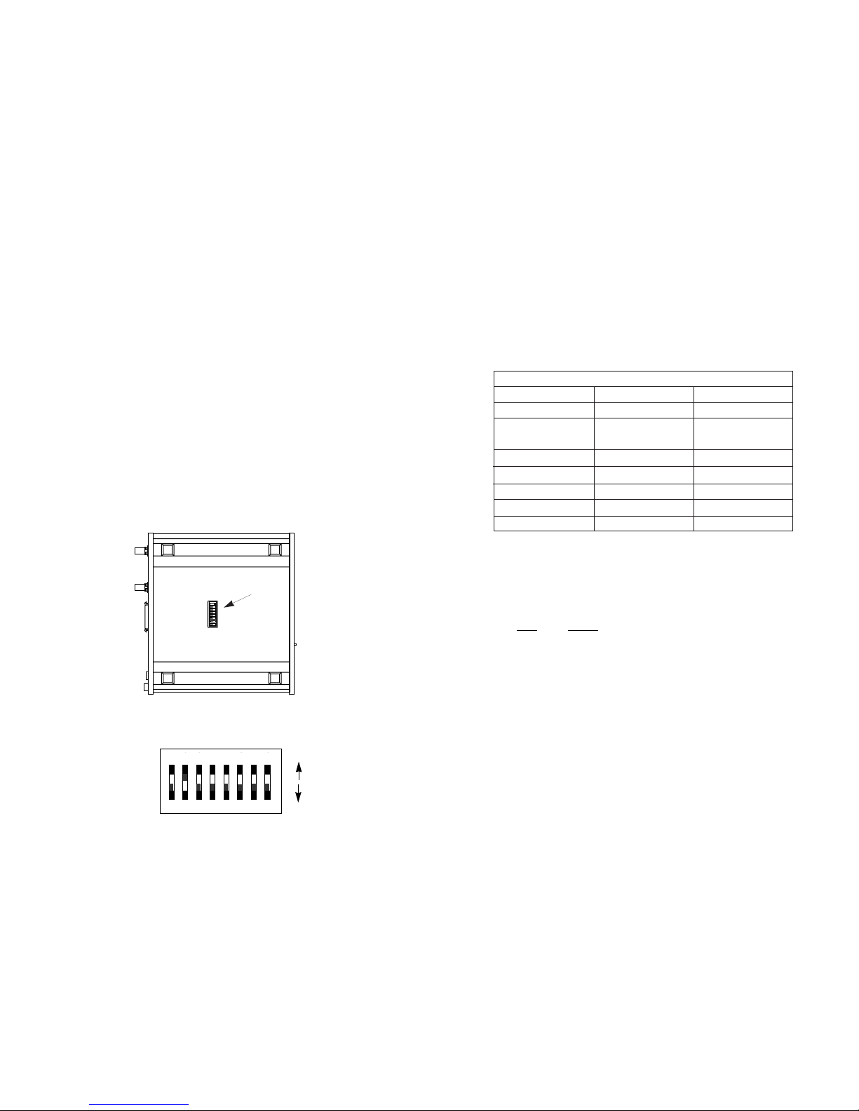
3.1 EXTERNAL DIP SWITCH SETTINGS
The Model 2703-X21’s DIP switch set is located on the underside
of the unit (see Figure 1, below). Figure 2 (below), shows the
orientation of the switch set. All possible settings for the Model 2703X21’s switches are presented in the summary table and descriptions on
the following pages. If you have additional questions regarding
configuration, contact Patton Technical Support at (301) 975-1000.
3 4
Figure 2. Close up of configuration switches
OFF
12345678
DHS-8
OFF
ON
Figure 1. Underside of Model 2703, showing external DIP switch location
S1 SUMMARY TABLE
Position Function Factory Default
S1-1 Clock Master/Slave On Master
S1-2 Rate Adaptation Off
S1-3 Rate Adaptation Off
S1-4 Test Enable Off Front Panel
S1-5 Data Inversion Off Not Inverted
S1-6 Not Used Off N/A
S1-7 Not Used Off N/A
S1-8 Not Used Off N/A
}
2.048 Mbps
S1
1 2 3 4 5 6 7 8
ON
Page 4

S1-2 and S1-3: Rate Adaptation
Switches S1-2 and S1-3 are set in combination to allow the Model
2703-X21 to adapt to terminal devices running at data rates of less than
2.048 Mbps (The network rate remains 2.048 Mbps regardless of the
terminal rate adaptation setting). The setting you select should match
the data rate of your terminal device.
S1-2 S1-3 Setting
Off Off 2.048 Mbps
On Off 1.024 Mbps
Off On 512 kbps
On On 256 kbps
S1-4: Loopback Test Enable
Depending upon the setting of switch S1-4 the Model 2703-X21 will
either be continually in loopback mode, or loopback mode will be
enabled by pressing and holding the front panel switch. Since the
front panel switch is spring loaded–it returns to “Normal” operation
when pressure is released–this DIP switch provides a way of leaving
the Model 2703-X21 in “unattended” loopback mode for remote test
purposes.
S1-4
Setting
On Continual “unattended” loopback mode
Off Loopback activation by front panel switch
S1-5: Data Inversion
The setting for switch S1-5 determines whether or not the data
stream from the local DTE is inverted within the Model 2703-X21 before
being passed to the G.703 network. The ability to invert the data
stream may be necessary when the Model 2703-X21 is being used with
an embedded G.703 device that inverts the data on the remote end.
Normally, data inversion is not necessary.
S1-5
Setting
On Data inverted
Off Data not inverted
S1-6, S1-7 & S1-8 Not Used
5
3.2 INTERNAL JUMPER SETTINGS
The Model 2703-X21’s seven jumpers are located on the PC board
inside the unit. To access the jumpers, follow these instructions:
1. Insert a flat head screw driver into an open slot on either side
of the case, as in Figure 3. Twist the screw driver head slightly
and the top half of the case will separate from the lower half,
as in Figure 4, below.
2. Remove the Network Interface Module by lifting gently upward
on it until it comes free from the Model 2703-X21 main PC
board.
3. Slide out the Network Interface Module and locate the jumpers
on the bottom side of the board.
4. Configure the jumpers according to the section below and
return the Network Interface Module and cover to their proper
positions.
The internal jumpers mounted on the Model 2703-X21’s PC board
(labeled LK1 - LK7) are used to configure the 75 ohm or 120 ohm
network link parameters. Figure 5 (below) shows the location of the
Model 2703’s jumpers on the internal PC board.
6
Figure 3. Opening the 2703 Case with a Small Screwdriver
Figure 4. Opening the 2703 Case With a Small Screwdriver
NOTE: Revision B Firmware (or newer, Implemented 6/19/98)
has been adopted to correct signal polarity at 1.024 Mbps, 512
kbps, and 256kbps. To operate Revision B Firmware units with
Revision A (or older) units at one of these sub-rates, you must
invert invert the data (Switch S1-5 On. See Below) (Firmware
revision level is printed on the label on the bottom of the unit).
Page 5

LK1: 75 Ohm Transmit Shield-to-Ground Connection
This setting determines whether the shield of the 75 Ohm (coax)
transmit cable is connected to earth ground. This connection must be
made when operating in 75 Ohm (unbalanced) mode. Conversely, this
connection must not be made when operating in 120 Ohm (balanced)
mode.
LK1 Setting
Strap On 75 Ohm TX Shield-to-GND Connection Made
Strap Off 75 Ohm TX Shield-to-GND Connection Broken
LK2: 75 Ohm Receive Shield-to-Ground Connection
This setting determines whether the shield of the 75 Ohm (coax)
receive cable is connected to earth ground. This connection is optional
when operating in 75 Ohm (unbalanced) mode. This connection must
not be made when operating in 120 Ohm (balanced) mode.
LK2 Setting
Strap On 75 Ohm RX Shield-to-GND Connection Made
Strap Off 75 Ohm RX Shield-to-GND Connection Broken
LK3: DIP Switch S1-1 Enable
This strap is reserved for future use and must remain Of
f.
LK3 Setting
Strap On Not a Valid Setting
Strap Off Normal Setting
LK4: 120 Ohm Shield-to-Ground Connection
This setting determines whether the shield of the 120 Ohm
(modular) cable is connected to earth ground. This connection is
optional when operating in 120 Ohm (balanced) mode. This connection
must not
be made when operating in 75 Ohm (unbalanced) mode.
LK4 Setting
Strap On 75 Ohm RX Shield-to-GND Connection Made
Strap Off 75 Ohm RX Shield-to-GND Connection Broken
The table below shows the factory default jumper settings.
Following the table are descriptions for each jumper.
NOTE: one combination of jumper settings is required for 75 ohm
operation, and another combination is required for 120 ohm
operation. The Model 2703 is factory configured for 75 ohm
operation.)
7 8
JUMPER SUMMARY TABLE
Jumper Function 75 ohm 120 ohm Factory Default
LK1 75 Ohm TX Shield to GND On Off On (connect)
LK2 75 Ohm RX Shield to GND Opt.* Off Off (disconnect)
LK3
Reserved
Off
LK4 120 Ohm Shield to GND Off Opt. Off (disconnect)
LK5 Configuration Auto-Sense On Opt. On (enabled)
LK6 75 Ohm Input Impedance On Off
LK7 75 Ohm Input Impedance On Off
}
On (75 Ohm)
*Opt. = optional setting, all others are required for proper operation
Figure 5. Jumper locations on Model 2703 PC board.
LK6
LK7
LK5
LK3
LK2
LK4
LK1
Page 6

LK5: Configuration Auto-Sense
This setting determines whether the host can automatically sense
the configuration of the Applique. The operation of the Applique is not
affected by this jumper setting. Auto-sense should be enabled when
operating in 75 Ohm (unbalanced) mode. Current interface standards
do not list this feature for 120 Ohm (balanced) mode.
LK5 Setting
Strap On Auto-sense enabled
Strap Off Auto-sense disabled
LK6 & LK7: 75 Ohm Termination Impedance
This jumper sets the termination impedance correctly for 75 Ohm
operation. Both jumpers must
be in place when operating in 75 Ohm
(unbalanced) mode. Conversely, both jumpers mustbe removed when
operating in 120 Ohm (balanced) mode.
LK6 LK7 Setting
On On 75 ohm operation
Off Off 120 ohm operation
3.3 POWER SUPPLY OPTIONS
The Model 2703-X21 is available with three power supply options:
The
Standard
power supply option (Model 2703-X21 or 2703-X21-
230) is factory configured for either 115 or 230 VAC, depending on
how the product is ordered, and is available with a variety of
domestic and international power cords (see Appendix C).
The
Universal Interface
power supply option (Model 2703-X21-UI)
operates in environments ranging from 85 to 265 VAC, with no reconfiguration necessary (see Appendix C for available domestic
and international power cords).
The
DC
power supply option (Model 2703-X21-DC) operates in 48
VDC environments and is equipped with a 3-pin “terminal strip”
style DC power cord.
9 10
WARNING! There are no user-serviceable parts in the
power supply section of the Model 2703-X21. Voltage
setting changes and fuse replacement should only be
performed by qualified service personnel. Contact
Patton Electronics Technical support at (301)975-1007 for
more information.
Page 7

4.0 INSTALLATION
Once the Model 2703-X21 is properly configured, it is ready to
connect to your system. This section tells you how to properly connect
the Model 2703-X21 to the G.703 network and terminal device
interfaces.
4.1 CONNECTION TO THE G.703 NETWORK
The Model 2703-X21 supports 2.048 Mbps communication over an
unstructured G.703 network. Both 120 ohm twisted pair and 75 ohm
coax interfaces are provided on the rear panel of the Model 2703-X21
(see Figure 6, below). Be sure the unit is configured properly to operate
in either 120 ohm or 75 ohm mode, and that the network connection is
grounded appropriately (see Section 3.0).
4.1.1 Twisted Pair (120 OHM) Connection
The Model 2703-X21 is equipped with a single RJ-45 jack for
connection to a 120 ohm twisted pair G.703 network interface. The
pinout of this jack is as follows:
RJ-45
Pins SIGNAL
1 & 2 . . . . . . . . . . . . Receive pair (from network)
3. . . . . . . . . . . . . . . . Shield reference point
4 & 5 . . . . . . . . . . . . Transmit pair (to network)
6. . . . . . . . . . . . . . . . Shield reference point
7. . . . . . . . . . . . . . . . Not used
8. . . . . . . . . . . . . . . . Not used
4.1.2 Dual Coax BNC (75 OHM) Connection
In addition to the 120 ohm twisted pair connection, the Model 2703X21 is equipped with dual female BNCs (TX and RX) for connection to
a 75 ohm dual coax G.703 network interface. The outer conductor of
the coax cables is isolated from system earth ground.
4.2 CONNECTION TO THE TERMINAL DEVICE
The Model 2703-X21 is wired as a DCE, and–when configured
properly–supports communication with an X.21 DTE device. The Model
2703-X21 is equipped with a DB-15 female connector and uses a
standard X.21 patch cable, wired
straight through
. If you wish to
construct your own terminal adapter cable, please consult the pinout
diagram in Appendix B.
4.3 CONNECTION TO THE POWER SOURCE
As described in Section 3.3, the Model 2703-X21 is available with
three power supply options: two AC and one DC. The two AC power
supply options (Standard and Universal) use a female IEC power cord
interface, for which Patton can supply various domestic and
international power cords. Please refer to Appendix C for specific
Patton part numbers when ordering power cords. The DC power
supply option uses a 3-pin terminal strip interface (Note: Please refer
to the Model 2703-X21 Service Manual for DC power supply wiring
instructions).
11 12
Network
DTE Interface
Figure 6. Model 2703 rear panel
(Model 2703-X21-DC has terminal strip)
Page 8

5.0 OPERATION
Once the Model 2703-X21 is properly configured and installed, it
should operate transparently. This sections describes power-up,
reading the LED status monitors, and using the built-in loopback test
modes.
5.1 POWER-UP
To apply power to the Model 2703-X21, first be sure that you have
read Section 3.3, and that the unit has the proper voltage setting and
fuse.
Failure to do so could result in damage to the unit and connected
equipment, and may constitute a fire hazard.
Having checked the
voltage setting, plug the AC power cord into both the Model 2703-X21
and the AC outlet. Then Power-up the unit using the rear Power switch.
Note: the “PWR” LED should glow when power is applied to the unit.
5.2 LED STATUS INDICATORS
The Model 2703-X21 features four front panel LEDs that indicate
the status of power, network connection, master clock and loopback
test. Figure 7 (below) shows the front panel location of each LED.
Following Figure 7 is a description of each LED’s function.
Power - Glows red when the Model 2703-X21 is
powered up.
Network - Glows green when the Model 2703-X21 is receiving
correctly encoded data from the line interface
equipment.
Master Clock- Glows green when the Model 2703-X21 is
configured as the master clock unit.
Loop - Glows green when the Model 2703-X21 is in
loopback mode.
13
5.3 LOOPBACK TEST (LAL)
The Model 2703-X21 is equipped with a Local Analog Loopback
(LAL) mode to assist in evaluating the operation of the local Model
2703-X21. Any data sent to the local Model 2703-X21 in this test mode
will be echoed (returned) back to the user device. For example,
characters typed on the keyboard of a terminal will appear on the
terminal screen. To perform a LAL test, follow these steps:
A. Activate LAL by moving the front panel toggle switch UP and
holding it in the “Loopback” mode. The “Loop” LED should glow. Once
LAL is activated, the Model 2703-X21 transmit output is connected to its
own receiver.
Note: The front panel switch is spring loaded, so it will return to
“Normal” operating mode when pressure is released. To put the Model
2703-X21 in
continual
loopback mode, for the purpose of performing a
BER test, move DIP switch S1-4 to the “ON” position (see Section 3.1).
B. Verify that the data terminal equipment is operating properly
and can be used for a test. If a fault is indicated, call a technician or
replace the unit.
C. Perform a BER (bit error rate) test on each unit. If the BER test
equipment indicates no faults, but the data terminal indicates a fault,
follow the manufacturer’s checkout procedures for the data terminal.
Also, check the interface cable between the terminal and the Model
2703-X21.
14
Model 2703
MegaLink-1 G.703/E1 Modem/Converter 2.048 Mbps
Power
Network
Master
Clock
Test Modes
Loop
Loopback
Normal
Figure 7. Model 2703 Front Panel
Page 9

APPENDIX B
MODEL 2703-X21 PIN CONFIGURATIONS
APPENDIX A
PATTON MODEL 2703 SPECIFICATIONS
Network Interface: G.703
Network Rate: 2.048 Mbps
Network Connectors: Two BNC (75 Ohm) and one
modular RJ-45 connector (120
Ohm)
Terminal Interface: X.21 on female DB-15 connector
Terminal Rate: 2.048 Mbps, 1.024 Mbps, 512 kbps
or 256 kbps
Diagnostics: Loopback Test
Indicators: LEDs for power, network, master
clock and loopback test
Clocking: Internal (Master) or Network
Recovered (Slave) clock
Receiver Sensitivity: -10 dB (0dB = 2.4V)
Power: 85/265 VAC (switch selectable),
50/60 Hz; 85-265 VAC, 50/60 Hz
(universal input option); 48 VDC
(option)
Temperature Range: 0-50°C (32-122°F)
Altitude: 0-15,000 feet
Humidity: 5 to 95% noncondensing
Dimensions: 7.3” x 6.6” x 1.62” (185mm x
168mm x 41mm)
Weight: 2.02 lbs.
15 16
CCITT X.21 INTERFACE (DB-15)
1 FRAME GROUND
2 TRANSMITTED - A
3 CONTROL - A
4 RECEIVE - A
5 INDICATION - A
6 SIGNAL TIMING - A
7
8 SIGNAL GROUND
TRANSMIT B 9
CONTROL B 10
RECEIVE B 11
INDICATION B 12
14
15
SIGNAL TIMING 12
1- Frame Ground
2- Transmit - A
3- Control - A
4- Receive - A
5- Indication - A
6- Signal Timing - A
8- Signal Ground
Transmit - B - 9
Control - B -10
Receive - B -11
Indication - B -12
Signal Timing -B 13
Page 10

APPENDIX C
FACTORY PARTS AND ACCESSORIES
C-1 Basic Standalone Units
The Patton Model 2703-X21 standalone digital modem is available
in three versions, depending upon the power supply installed. The
Standard and Universal Interface versions are supplied with a power
cord,
which must be specified in the model number when ordering
. The
DC version is supplied without power cord.
All versions of the Model 2703-X21 are supplied without a terminal
(DTE) interface cable. This cable may be ordered separately, or may
be supplied by the user.
Standard power supply option,
switchable between 115 and 230 VAC......................Model 2703-X21/*
Universal Interface power supply option,
operates in environments ranging from
85 to 265 VAC.......................................................Model 2703-X21-UI/*
DC power supply option,
operates in 48 VDC environments,
equipped with a 3-pin “terminal strip”
for DC power connection.......................................Model 2703-X21-DC
C-2 AC Power Cords
Power cord must be specified when ordering Models 2703-X21 or
2703-X21-UI. If power cord is omitted, suffix “K” will be assigned.
Ordering Suffix (*) Power Cord Description
A.....................................Continental Europe, CEE 7
C.....................................Australia, New Zealand
D.....................................United Kingdom
E.....................................Denmark
F.....................................France/Belgium
G.....................................India
H.....................................Israel
I ......................................Italy
J......................................Japan
K.....................................North America
L .....................................Switzerland
Example: 2703-X21-UI/D = Universal Interface w/ UK power cord.
APPENDIX D
SAFETY WARNINGS AND REQUIREMENTS
These warning notices apply to the Input Port, the port marked
“Network”.
Warning: The port marked “SAFETY WARNING: see instructions
for use” does not provide isolation sufficient to satisfy the requirements
of BS6301; apparatus connected directly to this port should either have
been approved to BS6301 or have previously been evaluated against
British Telecommunications plc (Post Office) Technical Guides 2 or 26
and given permission to attach. Any other usage will invalidate the
approval of the Interface Module.
Interconnection of the Interface Module (the port marked
“Network”) directly, or by way of any other apparatus, with ports on
other apparatus (marked or not so marked) may produce hazardous
conditions on the network. Users should seek advice from a competent
engineer before such a connection is made.
The Interface Module is approved as a Host Independent Appliqué.
As such the Interface Module is only approved for use with a host, and
with host attachments, that are either type approved in their own right,
or, if supplied after March, 1989, are covered by terms of the General
Approval number NS/G/1234/J/100003. A Host supplied under the
terms of the General Approval number NS/G/1234/J/100003 satisfies
the conditions of the paragraph above.
The Interface Module must not be modified in any way. Any form
of modification invalidates the approval for connection, and the Patton
warranty of the unit.
The terms of the approval require that there must be a minimum
distance (5mm) between the Interface Module and any other part of the
host, including other Interface Modules. This condition is met by default
when the Appliquè is installed in a Patton enclosure in accordance with
the instructions. If voltages greater than 250V are present in the host ,
users should refer to a competent safety engineer for advice.
It is a condition of the approval that a copy of these user
instructions and safety warnings must be supplied with the host.
Failure to provide the Interface Module user instructions with the host
will invalidate the Appliquè approval.
Failure to install the Interface Module in accordance with these
instructions will invalidate the approval. If you experience difficulties, or
are in any doubt, please contact your Patton representative.
17 18
 Loading...