

Page 1

USER
MANUAL
MODEL 2702
G.703 Interface Converter
SALES OFFICE
(301) 975-1000
TECHNICAL SUPPORT
(301) 975-1007
http://www.patton.com
Part# 07M2702-UM
Doc# 08605U2-003
Rev. C
Revised 10/26/06
CERTIFIED
An ISO-9001
Certified Company
Copyright © 2006
Patton Electronics Company
All Rights Reserved.
Page 2

PATTON MODEL 2702
TABLE OF CONTENTS
Section
Page
1.0 General Information...............................................................2
1.1 Warranty Statement
1.2 Radio and TV Interference
1.3 CE and Telecommunication Approvals
1.4 Service Information
2.0 General Information...............................................................6
2.1 Features
2.2 General Product Description
2.3 Supported Applications
2.3.1 The 2702 as the Interface Between the Telco & CPE
2.3.2 The 2702 as the High-Speed Short Range Modem
3.0 Configuration .........................................................................7
3.1 DIP Switch Configuration
4.0 Installation ..........................................................................10
4.1 DTE Interface Connection
4.2 Network Interface Connection
4.3 Power Connection
4.3.1 Using the AC Power Supply (100-240VAC)
4.3.2 Supplying DC Power
4.3.3 Supplying Power via Pin KK
5.0 Operation .............................................................................12
5.1 LED Descriptions
5.2 Loop (V.54 & Telco) Diagnostics
5.2.1 Operating Local Loopback (LL)
5.2.2 Operating Remote Digital Loopback (RL)
Appendix A - Specifications ........................................................15
Appendix B - Cable Recommendations .....................................16
Appendix C - Factory Replacement Parts and Accessories.......17
Appendix D - Interface Pin Assignments....................................18
Appendix E - Power Supply Interface.........................................20
1.0 GENERAL INFORMATION
Thank you for your purchase of this Patton Electronics product.
This product has been thoroughly inspected and tested and is warranted for One Year parts and labor. If any questions or problems arise
during installation or use of this product, please do not hesitate to contact Patton Electronics Technical Services at (301) 975-1007.
1.1 WARRANTY STATEMENT
Patton Electronics warrants all Model 2702 components to be
free from defects, and will—at our option—repair or replace the product should it fail within one year from the first date of shipment.This
warranty is limited to defects in workmanship or materials, and does
not cover customer damage, abuse, or unauthorized modification. This
product contains no serviceable parts; therefore the user shall not
attempt to modify the unit in any way. If this product fails or does not
perform as warranted, your sole recourse shall be repair or replacement as described above. Under no condition shall Patton
Electronics be liable for any damages incurred by the use of this
product. These damages include, but are not limited to, the following:
lost profits, lost savings and incidental or consequential damages arising from the use of or inability to use this product. Patton Electronics
specifically disclaims all other warranties, expressed or implied, and
the installation or use of this product shall be deemed an acceptance
of these terms by the user. In the event the user detects intermittent or
continuous product malfunction due to nearby high power transmitting
radio frequency equipment, the user is strongly advised to use only
data cables with an external outer shield bonded to a metal or metalized connector.
1 2
Page 3

1.2 RADIO AND TV INTERFERENCE
The Model 2702 generates and uses radio frequency energy, and
if not installed and used properly-that is, in strict accordance with the
manufacturer's instructions-may cause interference to radio and television reception. The Model 2702 has been tested and found to comply
with the limits for a Class Acomputing device in accordance with the
specifications in Subpart J of Part 15 of FCC rules, which are designed
to provide reasonable protection from such interference in a commercial installation. However, there is no guarantee that interference will
not occur in a particular installation. If the Model 2702 does cause
interference to radio or television reception, which can be determined
by disconnecting the cables, the user is encouraged to try to correct
the interference by one or more of the following measures: moving the
computing equipment away from the receiver, re-orienting the receiving
antenna, and/or plugging the receiving equipment into a different AC
outlet (such that the computing equipment and receiver are on different
branches).
1.3 CE AND TELECOMMUNICATION APPROVALS
The CE symbol on your Patton Electronics equipment indicates
that it is in compliance with the Electromagnetic Compatibility (EMC)
directive and the Low Voltage Directive (LVD) of the Union European
(EU). ACertificate of Compliance is available by contacting Technical
Support.
The Model 2702 is in compliance with the Telecommunication
technical requirements CRT-12; 2.048 Mbps digital unstructured
leased line (D2048U) attachment requirements for terminal equipment
interface.
3
1.4 SERVICE INFORMATION
All warranty and non-warranty repairs must be returned freight
prepaid and insured to Patton Electronics. All returns must have a
Return Materials Authorization number on the outside of the shipping
container. This number may be obtained from Patton Electronics
Technical Support at:
tel: (301) 975-1007;
email: support@patton.com
www: http://www.patton.com.
NOTE: Packages received without an RMA number will not be
accepted.
Patton Electronics' technical staff is also available to answer any
questions that might arise concerning the installation or use of your
Patton Model 2702. Technical Services hours: 8AM to 5PM EST,
Monday through Friday.
4
Page 4
2.0 GENERAL INFORMATION
Thank you for your purchase of this Patton Electronics product.
This product has been thoroughly inspected and tested and is warranted for One Year parts and labor. If any questions arise during installation or use of the unit, contact Patton Electronics Technical Services at
(301) 975-1007.
2.1 FEATURES
• Converts Synchronous unframed 2 Mbps G.703 to V.35
• Integral V.35 (M/34) Male connector (6 Pin Cisco router also
available)
• V.54 Compliant Loopback Diagnostics
• Easy to Read LEDs for TXD, RSD, ALM, LOTC, TST, and ERR
• AMI or HDB3 Line Coding
• Configuration via DIP Switches
• External 100-240VAC Power Supply
2.2 GENERAL PRODUCT DESCRIPTION
The Patton Model 2702 fits into an environment where high-speed
E1/G.703 services are being offered to customers with Router/FRADS
and other networking devices. These G.703 Interface Converters are
required to convert signals from the unstructured, synchronous line
interface - delivered by the carrier - to a 2 Mbps digital interface
required by the users networking equipment.
To accomplish this, the Model 2702 presents a RJ48C interface to
the line and a V.35 interface to the customer’s device. The V.35 interface is presented using a Male M/34 connector. Line coding and clock
options may be selected using internally accessible DIP Switches
If other interfaces are required, you may select our Model 2703 converter which presents the following interfaces: X.21, RS422/530,
V.36/RS449 and V.24/RS232. These interfaces are delivered through a
standard interface cable which connects to the Female DB25 on one
end and the desired interface on the other end. If other DTE speeds
are necessary, our Model 2094 connects Fractional E1 at nx64 speeds
up to 2 Mbps. Please see the interface converter section of the Patton
Catalogue for the required converter.
5
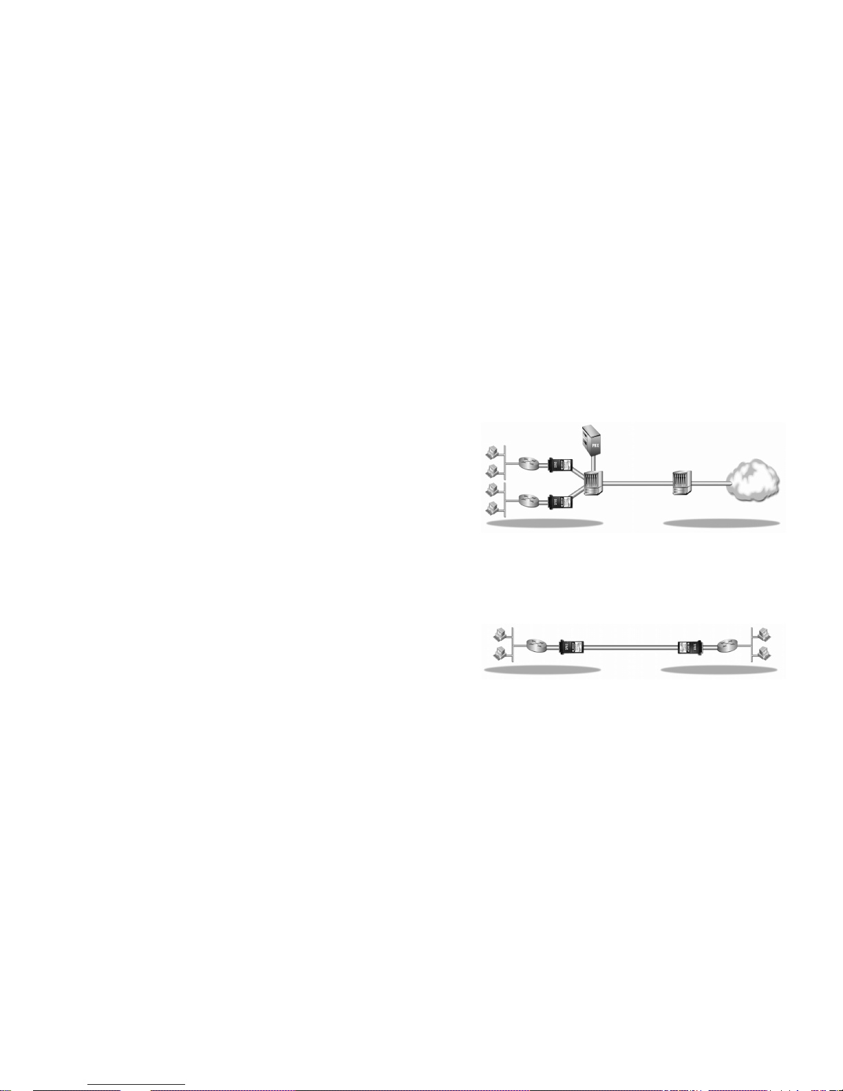
2.3 SUPPORTED APPLICATIONS
The Model 2702 provides a E1 network termination between E1
and customer premises equipment (CPE) such as a router. The Model
2702 can also be used as a high-speed short haul modem for campus
applications.
2.3.1 The 2702 as the Interface between the Telco and CPE
The Model 2702 provides the interface between an E1 multiplexer
and a router or switch (See below).
2.3.2 The 2702 as a High-Speed Short Range Modem
The Model 2702 can also be installed into high-speed campus
applications. In this application, a pair of Model 2702 units operate as
short range modems (See below).
6
Model 2702 Model 2702
Internet
LAN
Model 2702
MUX
DACS
E1/FE1
from
64kbps to
2.042Mbps
Customer Site
Service Provider’s Network
Customer Site
Service Provider’s Network
Page 5

3.0 CONFIGURATION
The Model 2702 features configuration capability via hardware
switches . This section describes all possible hardware switch configurations of the Model 2702.
3.1 DIP SWITCH CONFIGURATION
The Model 2702 has eight internal DIP switches that allow configuration for a wide range of applications. The eight switches are
accessed by opening the plastic case with a small screwdriver. Figure
1 (below) shows the location of the DIP switches on the bottom of the
printed circuit board.
The Model 2702 DIP switches (SW1, SW3 & SW4) can be configured as either “On” or “Off”. Figure 2 (below) shows the orientation of
the DIP switches with respect to ON/OFF positions.
Default positions for Switches SW1, SW3, and SW4 are shown in
the table on the following page. Descriptions of each switch follow the
table.
7
Figure 1. Model 2702 bottom view, showing location of DIP switches
DIP Switches
OFF
ON
Figure 2. Close up of DIP switches showing ON/OFF positions.
NOTE: Switches SW2, SW5, SW6, SW7, and SW8 are not used.
Switch SW1: Line Coding
Use Switch SW1 to control the Network Line Coding options. Set
these options to be the same as the Line Coding given to you by your
Service Provider. If you are using two Model 2702s together as short
range modems, set both units identically.
SW4 Line Framing & Coding
Off HDB3
On AMI
Line Coding Options:
High Density Bipolar 3 (HDB3): In HDB3 coding, the transmitter
deliberately inserts a bipolar violation when excessive zeros
in the data stream are detected. The receiver recognizes
these special violations and decodes them as zeros. This
method enables the network to meet minimum pulse density
requirements. Use HDB3 unless AMI is required in your
application .
Alternate Mark Inversion (AMI): AMI coding does not inherently
account for ones density. To meet this requirement, the user
should ensure that the data inherently meets pulse density
requirements.
8
SWITCH SET SUMMARY TABLE
Position Function Factory Default Selected Option
SW1 Line Coding Off HDB3
SW3 Clock Mode Off
SW4 Clock Mode Off
Network
ON
OFF
Page 6

Switch SW3 and SW4: Clock Mode
SW3 is used to along with SW4 to determine the clock mode. For
example the Model 2702 can be set to external clock mode by setting
both SW3 and SW4 to the on position. Please refer to the Clock Mode
chart below for the desired settings.
CLOCK MODES
Network Clock Transmitter timing is derived from the received line
signal.
Internal Clock Transmitter clock is derived from an internal clock
source
External Clock Transmitter timing is derived from the local DTE
device. A2.048 MHz timing signal must be present a
at the external clock pin U and pin W on the M/34
connector.
Note: When using the 2702 as a high-speed short range modem, one
unit of the link must be configured in either internal or external clock,
and the other end must be configured for network clock mode, or both
units could be either Internal or External Clock. But both units cannot
be network clock mode in SRM applications
9
CLOCK MODE SETTINGS
SW3 SW4 Clock Mode
Off Off Network (Default)
Off On Internal
On On External
On Off Network
4.0 INSTALLATION
The Model 2702 is equipped with DTE, network, and power interfaces.
This section briefly describes connection to each.
4.1 DTE INTERFACE CONNECTION
The DTE/DCE interface is a V.35 DCE presented as an M/34 male
connector. This interface is designed to plug directly into a DTE interface (See Appendix D for V.35 interface pin assignments).
4.2 NETWORK INTERFACE CONNECTION
The Network Line Interface is an eight position keyed modular jack
configured as a RJ-48C. This interface will need to be configured to
match the line parameters (i.e. framing, line coding, etc.) supplied by
the central office.
NOTE: If the Model 2702 is being used for private short range
modem applications, the twisted pair cable connected to its port
will need to be a cross-over cable, and should be configured as
shown below. See Appendix D for Interface pin assignments.
10
Figure 3. Model 2702 twisted pair line interface.
SIGNAL PIN NO. PIN NO. SIGNAL
RX Data (Ring)
1 4 TX Data (Tip)
RX Data (Tip)
2 5 TX Data (Ring)
TX Data (Ring) 4 1 RX Data (Ring)
TX Data (Tip) 5 2 RX Data (Tip)
1
2
3
4
5
6
7
8
1
2
3
4
5
6
7
8
(RX) Receive (Ring)
(RX) Receive (Tip)
Shield
(TX) Transmit (Ring)
(TX) Transmit (Tip)
Shield
No connection
No connection
Signal NameRJ-48C Jack
Page 7

4.3 POWER CONNECTION
The Model 2702 offers three ways to supply external power: AC
power, DC power and interface power.
4.3.1 Using the AC Power Supply (100-240VAC)
The Model 2702 uses a 5VDC, 400mA universal input 100240VAC, power supply (center pin is +5V). The universal input power
supply is equipped with a male IEC-320 power entry connector. This
power supply connects to the Model 2702 by means of a barrel jack on
the rear panel. There are a variety of international power cords available for the universal power supply. The Model 2702 powers up as
soon as it is plugged into an AC outlet–there is no power switch.
4.3.2 Supplying DC Power
The 36-60 VDC DC to DC adapter is supplied with the DC version
of the Model 2702. The black and red leads plug into a DC source
(nominal 48VDC) and the barrel power connector plugs into the barrel
power supply jack on the 2702.
4.3.3 Supplying Power via pin KK
You may also supply DC power directly to pin KK of the V.35 interface. DC Power supplied to pin KK must be regulated 5VDC ± 5%,
300mA minimum.
NOTE: Model 2702 is factory configured to accept power from the
enclosed DC wall adapter (See Sections 4.3.1 and 4.3.2 above).
If you wish to supply power via pin KK on the interface, you must
change the setting of the
power supply jumper
on the printed circuit board See Appendix E. All power sources must be SELV
(Circuit, Safety Extra Low Voltage) specified. (See CENELEC
EN60950, Section 1.2.8.5)
11
5.0 OPERATION
Once the Model 2702 is installed and configured properly it is
ready to place into operation. This section describes the function of
the LED indicators, and the use of the loopback.
5.1 LED DESCRIPTIONS
The Model 2702 is equipped with seven LED indicators that monitor the status of communication. Figure 4 (below) shows the location
of the LEDs on the Model 2702 front panel.
TXD When the unit sends a one, the TXD LED
is turned on. When it sends a zero, the
TXD LED is turned off. Moreover, the TXD
LED is active only in active DS0 channels.
In inactive channels, the TXD LED is off.
RXD When the unit receives a one, the RXD
LED is turned on. When it receives a zero,
the RXD LED is turned off. Moreover, the
RXD LED is active only in active DS0 channels. In inactive channels, the RXD LED is
off.
12
RXD
LOS
ALM
ERR
T/L
PWR
TXD
Model 2702
G.703 Interface Converter
Figure 4. Top of Model 2702, Showing LED Indicators
To Power
Supply Jack
To -48VDC
Source
-Vin
+Vin
SWITCHING POWER SUPPLY
MODEL : SYD1106-0505
INPUT : 36-60V 0.2A MAX
OUTPUT : +5V 1.0A
OUTPUT POWER : 5W MAX
S/N: G01234567890
MADE IN CHINA BY SUNNY
Black lead (-V)
Red lead (+V)
Barrel power connector
Page 8

13
LOTC The Loss of Transmit Clock LED lights
when
the unit detects that there is no transmit
clock.
ALM The alarm LED indicates the loss of carrier,
i.e., no activity on the network.
ERR The error LED is not used in Model 2702.
TST The test indicator LED blinks with a specific
pattern depending on the type of test mode.
When the unit is in local analog loop, the
LED will blink on briefly. When the unit is in
remote loop, the TST LED will blink off
briefly. The test mode is V.54 Loopback &
Local loopback.
PWR The power indicator LED will remain lit while
the unit is powered. It turns off when the
unit is not powered.
5.2 LOOP (V.54 & TELCO) DIAGNOSTICS
The Model 2702 offers two V.54 loop diagnostics and is compatible with two Telco loop diagnostics. Use these diagnostics to test the
NTU and any communication links. These tests can be activated via
signals on the DTE interface.
5.2.1 Operating Local Loopback (LL)
The Local Loopback (LL) test checks the operation of the local
Model 2702, and is performed separately on each unit. Any data sent
to the local Model 2702 in this mode will be echoed (returned) back to
the user device. To perform a LL test, follow the steps below.
1. Activate the “LL” signal on the DTE pin L. If you are not sure
which lead is the “LL” signal, please refer to Appendix D.
2. Verify that the data terminal equipment is operating properly
and can be used for a test.
3. Perform a V.52 BER (bit error rate) test. If the BER test equipment indicates no faults, but the data terminal indicates a
fault, follow the manufacturer’s checkout procedures for the
data terminal. Also, check the interface cable between the
terminal and the Model 2702.
14
5.2.2 Operating Remote Digital Loopback (RL)
The Remote Digital Loopback (RL) test checks the performance of
both the local and remote Model 2702, as well as the communication
link between them. To perform a RDL test, follow the steps below.
1. Activate the “RL” signal on the DTE pin N. If you are not sure
which lead is the “RL” signal, please refer to Appendix D.
2. Perform a bit error rate test (BERT) or using a separate BER
Tester. If the BER test indicates a fault, and the Local Line
Loopback test was successful for both NetLink™s, you may
have a problem with the twisted pair line connection.
Page 9

15
APPENDIX A
PATTON MODEL 2702
SPECIFICATIONS
Network Data Rate: 2.048 Mbps
+
50ppm
Network Connector: RJ-48C
Nominal Impedance: 120 ohm (75 ohm available when using
Patton Model 460 Balun)
DTE/DCE Interface: V.35 (DCE Orientation) on Male M/34
Line Coding: Selectable AMI or HDB3
Line Framing: G.703 (Unframed)
Clocking: Network, Internal, External (from DTE)
DTE Data Rates: 2.048 Mbps
Diagnostics: V.54 Loopback & Local Loopback
Indicators: Power, Transmit Data, Receive Data,
Alarm, Loss of Tx Clock, Test Mode,
Error
Configuration: 8-Position DIP Switch
Power: Regulated 5VDC+5%, 300 mA mini-
mum
Humidity: Up to 90% non-condensing
Temperature: 0 to 50oC
Dimensions: 4.8”L x 2.0”W x 0.88”H (12.2 x 5.1 x 2.2
cm)
16
APPENDIX B
PATTON MODEL 2702
CABLE RECOMMENDATIONS
The Patton Model 2702 has been performance tested by Patton
technicians using twisted-pair cable with the following characteristics:
W
ire Gauge Capacitance Resistance
19 AWG 83nf/mi or 15.72 pf/ft. .0163 Ohms/ft.
22 AWG 83nf/mi or 15.72 pf/ft. .0326 Ohms/ft.
24 AWG 83nf/mi or 15.72 pf/ft. .05165 Ohms/ft.
To gain optimum performance from the Model 2702 , please keep
the following guidelines in mind:
•
Always
use twisted pair wire—this is not an option.
• Use twisted pair wire with a capacitance of 20pf/ft or less.
• Avoid twisted pair wire thinner than 26 AWG (i.e. avoid AWG
numbers higher than 26)
• Use of twisted pair with a resistance greater than the above
specifications may cause a reduction in maximum distance obtainable. Functionality should not be affected.
• Many environmental factors can affect the maximum distance
obtainable at a particular site. Use the above data rate/distance
table as a
general guideline only.
Page 10

17
APPENDIX C
PATTON MODEL 2702
FACTORY REPLACEMENT PARTS
AND ACCESSORIES
Patton Model #
Description
2702/CM/UI.....................V.35 to E1 Converter (V.35 M/34 Male,
UI)
10 - 09F...........................6 Foot Control Port Cable, 25 mm to
DB9F
07M2702 .........................User Manual
08055DCUI......................Universal Input Power Supply
18
APPENDIX D
PATTON MODEL 2702
INTERFACE PIN ASSIGNMENT
RJ-48C E1 Network Interface
(RJ-48S Female Modular Jack)
Pin #
Signal
1 RX Data (RING)
2 RX Data (TIP)
4 TX Data (RING)
5 TX Data (TIP)
Page 11

19
APPENDIX D
((ccoonnttii nnuueedd))
PATTON MODEL 2702
INTERFACE PIN ASSIGNMENT
M/34 Connector, Terminal Interface
Pin #
Signal
A GND (Earth Ground/Shield)
B SGND (Signal Ground)
D CTS (DCE Source)
E DSR (DCE Source, Always On)
F CD (DCE Source)
L LL (Local Loop, DTE Source)
M TM (Test Mode Indicator (DCE Source)
N RL (Remote Loop, DTE Source)
P TD (Transmit Data +, DTE Source)
R RD (Receive Data +, DCE Source)
S TD/ (Transmit Data -, DTE Source)
T RD/ (Receive Data -, DCE Source)
U SCTE (Transmit Clock+, DTE Source)
V RC (Receiver Clock +, DCE Source)
W SCTE/ (Transmit Clock-, DTE Source)
X RC/ (Receiver Clock -, DCE Source)
Y TC (Transmitter Clock +, DCE Source)
AA TC/ (Transmitter Clock -, DCE Source)
KK Aux. Power Input (+5VDC @ 300mA)
20
APPENDIX E
PATTON MODEL 2702
POWER SUPPLYINTERFACE
Via Main 5VDC power jack (J1)
Center Pin: 5VDC @ 300 mA
Outer Barrel: Ground
Barrel Plug: 2.1/5.5/10mm I.D./O.D./Shaft Length dimensions.
Jumper Position for Power via DC Power Jack (default):
Via Auxiliary Power Supplied to Pin KK on V.35 connector
DC Power supplied to pin KK must be 5VDC ± 5%, 300mA minimum.
Jumper Position for Power via Pin KK:
NOTE: Model 2702 is factory configured to accept power from the
enclosed DC wall adapter (See Sections 4.3.1 and 4.3.2 above).
If you wish to supply power via pin KK on the interface, you must
change the setting of the
power supply jumper
on the printed circuit board. All power sources must be SELV (Circuit, Safety Extra
Low Voltage) specified. (See CENELEC EN60950, Section
1.2.8.5)
 Loading...