

Page 1
USER
MANUAL
MODEL 2450
56/64 Kbps, 4-Wire
DDS & Clear Channel
CSU/DSU
SALES OFFICE
(301) 975-1000
TECHNICAL SUPPORT
(301) 975-1007
http://www.patton.com
Part# 07M2450-B
Doc# 099051U,
Rev. C
Revised 1/23/08
CERTIFIED
An ISO-9001
Certified Company
Page 2

Page 3

Your telephone company may make changes in its facilities,
equipment, operations or procedures that could affect the proper
operation of the Model 2450 Series. If this happens, the telephone
company should give you advance notice to prevent the interruption of
your service.
The telephone company may decide to temporarily discontinue
your service if they believe your Model 2450 Series may cause harm to
the telephone network. Whenever possible, they will contact you in
advance. If you elect to do so, you have the right to file a complaint
with the FCC. The telephone company may ask you to disconnect the
equipment from the telephone network until the problem has been
corrected or until you are certain that the Model 2400 Series is not
malfunctioning.
The following information may be required when applying to your
local telephone company for leased line facilities.
Service Digital Facility Service Order Network
T
ype Interface Code Code Jacks
56 Kbps 04 DU5 - 56 6.0F RJ48S
64 Kbps 04 DU5 - 64 6.0F RJ48S
1.3 SERVICE INFORMATION
All warranty and non-warranty repairs must be returned freight
prepaid and insured to Patton Electronics. All returns must have a
Return Materials Authorization number on the outside of the shipping
container. This number may be obtained from Patton Electronics
Technical Support: (301) 975-1007; http://www.patton.com; or,
support@patton.com. Notice: Packages received without an RMA
number will not be accepted. Patton Electronics' technical staff is also
available to answer any questions that might arise concerning the
installation or use of your Model 2400. Technical Service hours: 8AM
to 5PM EST, Monday through Friday.
1.4 CE NOTICE
The CE symbol on your Patton Electronics equipment indicates
that it is in compliance with the Electromagnetic Compatibility (EMC)
directive and the Low Voltage Directive (LVD) of the Union European
(EU). A Certificate of Compliance is available by contacting Patton
Technical Support.
2
Page 4

Page 5
3.0 CONFIGURATION
The Model 2450 is easy to install and is ruggedly designed for
excellent reliability: just set it and forget it. The following instructions
will help you set up and install the Model 2450 properly.
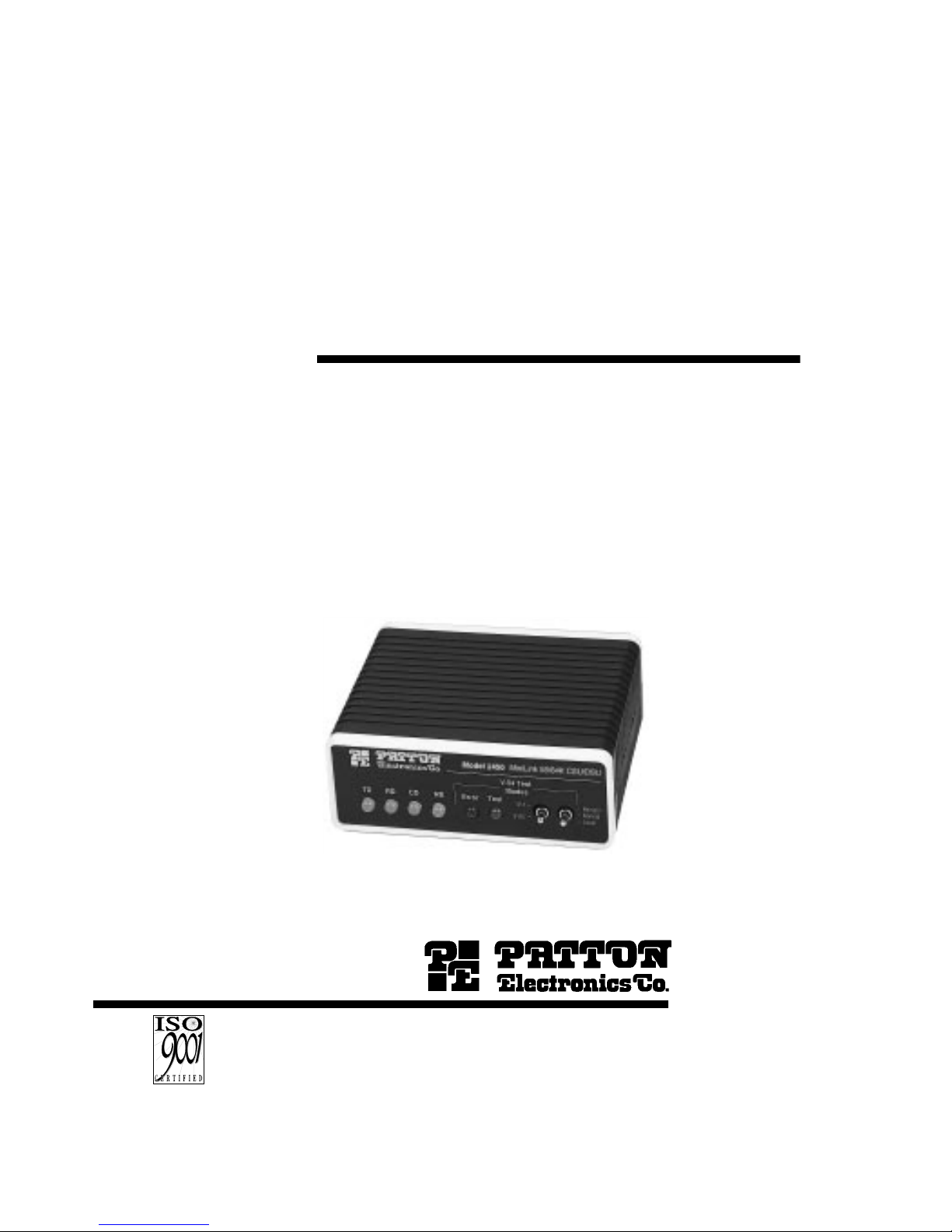
3.1 CONFIGURATION SWITCHES
The Model 2450 uses a mini DIP switch package that allows
configuration to a wide range of applications. This DIP switch is
externally accessible from the underside of the Model 2450 (see Figure
1, below), therefore you do not need to open the Model 2450's case
during configuration.
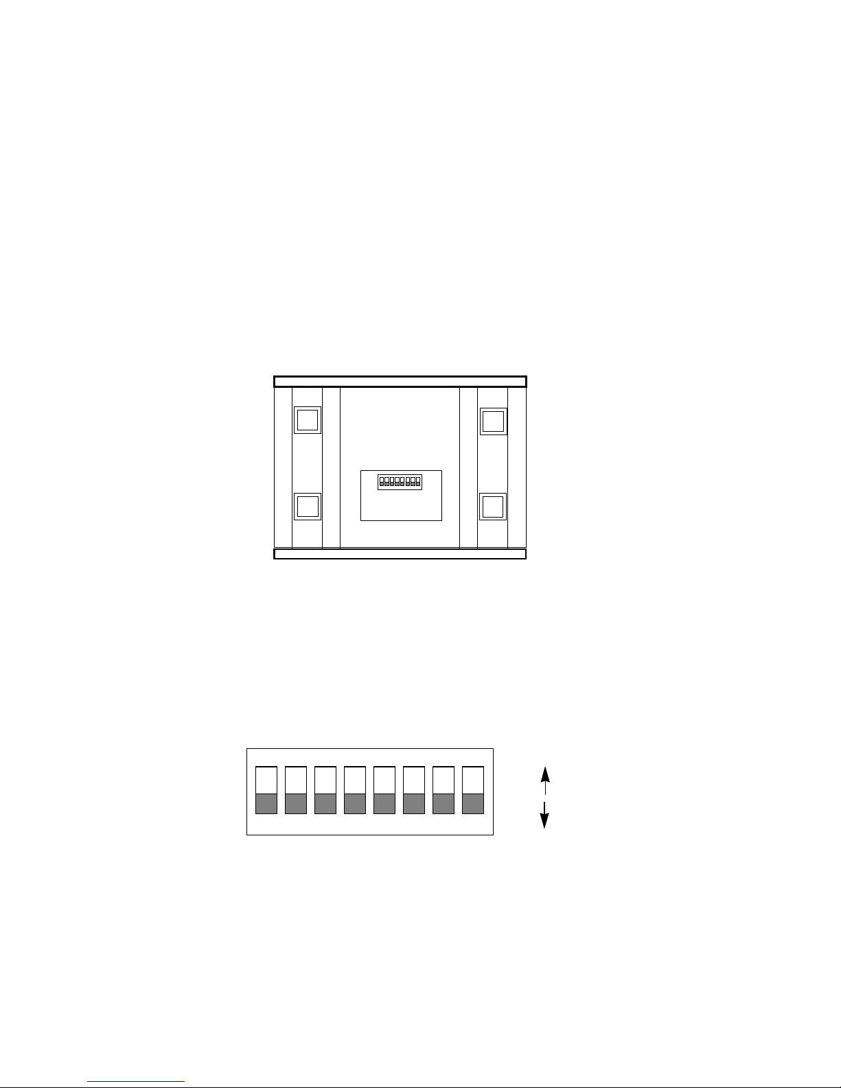
3.2 CONFIGURATION SWITCH SET “S1”
The switches shown in Figure 2 below and on DIP switch S1 control
clock mode, circuit assurance, RTS, data rate and test loop functions.
Following Figure 2 are factory default settings and detailed switch
descriptions for each switch.
4
Figure 2. Close-up of DIP switches showing “ON” and “OFF” positions
12345678
ON
OFF
ON
12345678
ON
REAR
FRONT
Figure 1. Underside of Model 2450, showing location of DIP switches
S1
Page 6

Page 7

Switch S1-3: Circuit Assurance
On dedicated circuits, the transmitter and the CTS output can be
configured to go On only when a working communication circuit is
established. If Circuit Assurance is used, enable it on only one end of
the communication link.
Circuit
S1-3
Assurance Description
On Enabled CTS will go low and the
transmitter will be held off if the
receiver is in the No Signal state
or CD is low
Off Disabled The transmitter and CTS will
operate without regard to the
receiver state
Switch S1-4: RTS
The RTS input can be forced on, ignoring the terminal’s RTS
signal. RTS controls the transmitter by either sending the user’s data
or sending an idle code.
S1-4
RTS Description
On Forced On Transmitter is always ON
Off Follows The RTS input controls the
DTE Signal transmitter
Switches S1-5: Data Rate
This switch controls the data rate on the line (RJ-48S port) and
must match the speed of your digital service.
S1-5
Setting
Off 56 kbps
On 64 kbps
6
Page 8

Page 9

4.0 INSTALLATION
The Model 2450 is designed for 4-wire, full duplex communication
over a DDS or Clear Channel carrier circuit, or over dedicated twisted
pair. This section will describe proper connection of the line interface,
the DTE (terminal) interface, and the AC power supply.
4.1 LINE (NETWORK) CONNECTION
The RJ-48S port on a Model 2450 CSU/DSU is prewired for a
standard TELCO wiring environment (see Figure 4, below). Connect
this port to the RJ-48S jack provided by your digital service carrier
using a
straight through
twisted pair cable between 19 and 26 AWG.
To be sure you have the right wiring, use the table below as a guide.
4.1.1 CONNECTING OVER PRIVATE TWISTED PAIR
If you are using a pair of Model 2450s as short range modems over
private twisted pair, make the connection between them using a twisted
pair
crossover cable
pinned according to the diagram below.
RJ-48S Cable (4-W
ire)
SIGNAL PIN# PIN# SIGNAL
TX+ 1-----------------------7 RX+
TX- 2-----------------------8 RXRX+ 7-----------------------1 TX+
RX- 8-----------------------2 TX-
87
Figure 4. Interface pinouts for Model 2450 RJ-48S jack.
1 (TX+)
2 (TX-)
3 (N/C)
4 (N/C)
5 (N/C)
6 (N/C)
7 (RX+)
8 (RX-)
1
2
3
4
5
6
7
8
Page 10

Page 11

5.0 OPERATION
Once you have configured the Model 2450 properly (see Section
3.0) and made line, DTE and power connections correctly (see Section
4.0), you are ready to operate the unit(s). (Note: the unit is operational
as soon as power is applied–there is no power switch.) This section
describes the LED status monitors, and use of the built-in V.54 and V.52
test modes.
5.1 LED STATUS MONITORS
The Model 2450 features six front panel status LEDs that indicate
the condition of the unit and communication link. Figure 6 (below)
shows the front panel location of each LED. Following Figure 6 is a
description of each LED's function.
• “TD” (Transmit Data) glows red to indicate an Idle condition or
Binary “1” data. Green indicates Binary “0” data.
• “RD” (Receive Data) glows red to indicate an Idle condition or
Binary “1” data. Green indicates Binary “0” data.
• “CD” (Carrier Detect) glows green when carrier is active. In 64
Kbps mode, CD glows red if there is no carrier, or if a bipolar
violation occurs. In 56 Kbps mode, CD glows red if there is no
carrier, if an Out-of-Service or Out-of-Frame violation occurs,
or if idle code is detected.
• “NS” (No Signal) glows red when there is no valid carrier. This
means the Model 2450 receiver has not detected a valid signal
from the digital service provider, or, in the case of short-haul
operation, from the remote Model 2540. If NS is lit, check for
an unplugged cable, broken wire or an incorrect Line Rate
selection.
Figure 6. Front view of Model 2450
Model 2450 MiniLink-I 56/64 CSU/DSU
TD RD
CD
NS
V.54 Test
Modes
Remote
Normal
Local
Error
Test
511
511E
Page 12

Page 13

5.2.2 Using Remote Digital Loopback (RDL)
The Remote Digital Loopback (RDL) test checks the performance
of both the local and remote Model 2450s, and the communication link
between them. Any characters sent to the remote Model 2450 in this
test mode will be returned back to the originating device. For example,
characters typed on the keyboard of the local terminal will appear on
the local terminal screen after having been passed to the remote Model
2450 and looped back. To perform an RDL test, follow these steps:
1. Activate RDL. This may be done in two ways: First, by moving
the front panel toggle switch UP to “Remote”, and; second, by raising
pin 21 on the interface. (Note: Make sure S1-7 is OFF).
2. Perform a V.52 BER test as described in Section 5.2.3. If the
BER test equipment indicates a fault, and the Local Analog Loopback
test was successful for both Model 2450s, you may have a problem
with the twisted pair line between the modems. You should then check
the twisted pair line for proper connections and continuity.
5.2.3 Using the V.52 BER Test
To use the V.52 BER tests in conjunction with the V.54 loopback
tests, follow these instructions:
1. Locate the “511/511E” toggle switch on the front panel of the
2450 and move it UP. This activates the V.52 BER test mode and
transmits a “511” pseudo-rando test pattern into the loop. If any errors
are present, the local modem’s red “Error” LED will blink sporadically.
2. If the above test indicates no errors are present, move the V.52
toggle switch DOWN, activating the “511/E” test with errors present. If
the test is working properly, the local modem's red “Error” LED will glow.
A successful “511/E” test will confirm that the link is in place, and that
the Model 2450’s built-in “511” generator and detector are working
properly.
Note: The above V.52 BER tests can be used independently of the
V.54 loopback tests. This requires two operators: one to initiate and
monitor the tests at the local Model 2450, and one to do the same at
the remote Model 2450. In this case, the test pattern sent by each
Model 2450 will not be looped back, but will be transmitted down the
line to the other Model 2450. Both operators must initiate and monitor
the tests simultaneously.
Page 14

Page 15

APPENDIX B
CABLE RECOMMENDATIONS
The following statements apply to the Model 2450 when used as a
short range modem over private twisted pair:
All Patton Electronics Company Short Range Modems (SRMs) are
tested to the distances published in our Catalogs and Specification
Sheets on twisted-pair cable with the following characteristics:
W
ire Gauge Capacitance Resistance
19 AWG 83nF/mi or 15.72 pF/ft. .0163Ω/ft.
22 AWG 83nF/mi or 15.72 pF/ft. .0326Ω/ft.
24 AWG 83nF/mi or 15.72 pF/ft. .05165Ω/ft.
26 AWG 83nF/mi or 15.72 pF/ft. .08235Ω/ft.
We fully expect that the Short Range Modems will operate on lines
with specifications different from those tested, but to reduce the
potential difficulties in the field, one should ensure that the cable being
used has similar or better characteristics (lower capacitance or lower
resistance).
Wire with capacitance of 20pF/ft. or less is suitable for all our Short
Range Modems . However, distances may vary from those published in
our catalog. Variations in wire resistance will also affect distance but
not functionality. Wire should be 26 AWG or larger (smaller AWG#).
Patton products are designed to withstand normal environmental
noise and conditions however, other environmental factors too
numerous to discuss in this format may affect proper operation of the
SRM’s.
Selection of the proper SRM for an application is critical to
maintaining Customer Satisfaction and should be taken seriously.
Certain models are better suited for particular applications and
environments than others.
Page 16

Page 17

APPENDIX D
INTERFACE PIN ASSIGNMENT
DDS/CLEAR CHANNEL INTERFACE
The DDS/Clear Channel Interface is an RJ-48S modular jack.
Pin #
Signal
1TX+
2TX3 no connection
4 no connection
5 no connection
6 no connection
7RX+
8RX-
MODEL 2450/C
M/34 CONNECTOR (V.35), TERMINAL INTERFACE
Pin #
Signal
A Frame Ground
B SGND (Signal Ground)
CRTS
DCTS
EDSR
FCD
L LL (Local Loop)
M TM (Test Mode)
N RL (Remote Loop)
PTD
RRD
STD/
T RD/
UXTC
VRC
WXTC/
X RC/
YTC
AA TC/
Page 18

Page 19

(APPENDIX D - Continued)
MODEL 2450/E
DB-25 CONNECTOR (V.35), TERMINAL INTERFACE
Pin #
Signal
1 Frame Ground
2 Transmit Data A
3 Receive Data A
4RTS
5CTS
6DSR
7 SGND (Signal Ground)
8CD
9 Receive Clock B
11 External Clock B
12 Transmit Clock B
14 Transmit Data B
15 Transmit Clock A
16 Recieve Data B
17 Receive Clock A
18 LL (Local Loop)
21 RL (Remote Loop)
24 External Clock A
25 TM (Test Mode)
Copyright ©
Patton Electronics Company
All Rights Reserved
Page 20

 Loading...