

Page 1
USER
MANUAL
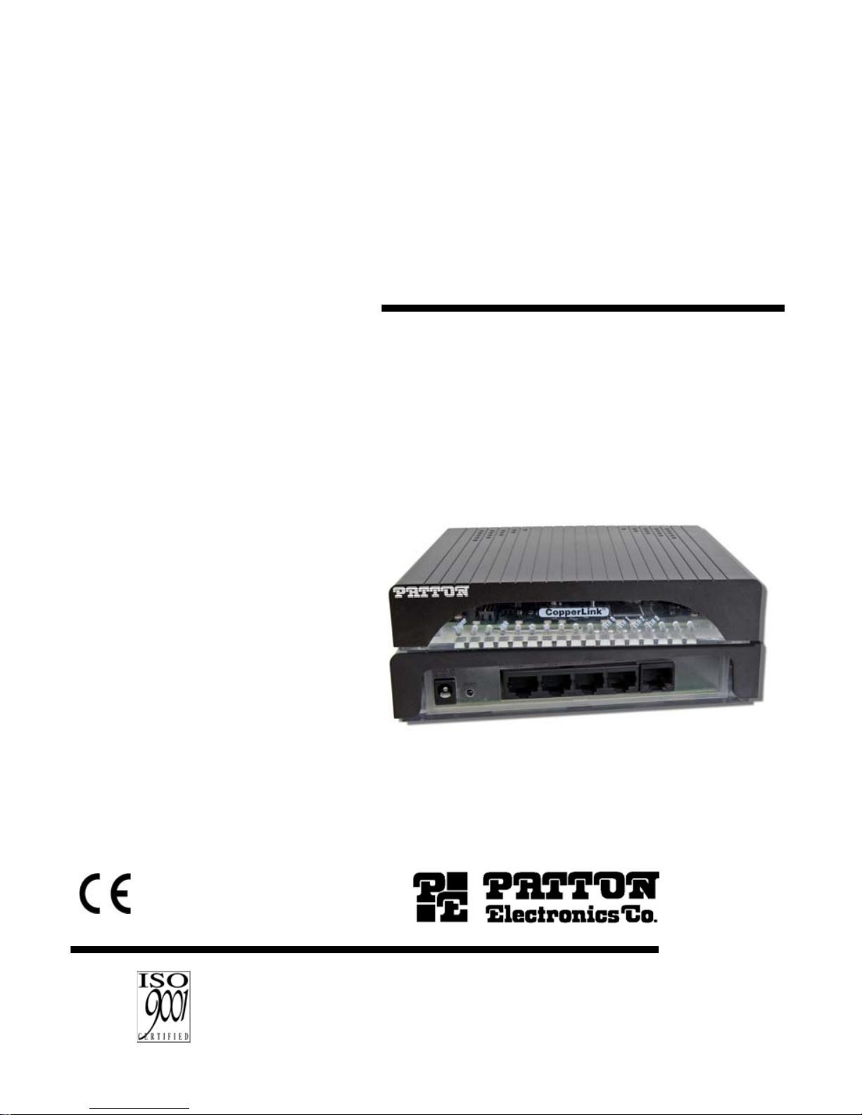
MODEL 2174
CopperLINK™ High Speed
Ethernet Extender
This is a Class A device and is not intended for
use in a residential environment.
Part# 07M2174-U M
Rev . A
Revised 9/23/11
An ISO-9001Certified
Company
SALES OFFICE
(301) 975-1000
TECHNICAL SUPPORT
(301) 975-1007
Page 2

CONTENTS
1.0 Warranty Information ................................................................. 4
1.1 Regulatory Information ................................................................. 4
EMC Directive:......................... ...... ............................ ...... ..... ...... .. 4
Low-Voltage Direcive (Safety):..................................................... 4
PSTN:.................................................. ......................................... 4
1.2 Radio and TV Interference (FCC Part 15).................................... 4
1.3 CE Declaration of Conformity....................................................... 5
1.4 Authorized European Representative........................................... 5
1.5 Service.......................................................................................... 5
1.6 Safety When Working With Electricity .......................................... 6
2.0 General Information.................................................................... 8
2.1 Features........................................................................................ 8
2.2 Description.................................................................................... 8
3.0 Installation................................................................................... 9
3.1 Connecting the Line Interface..................................................... 11
Connecting the Line Interface for Model 2174/EUI or 2174/TB.. 11
Connecting the Line Interface for Model 2174/BNC................... 12
3.2 Connecting the 10/100Base-T Ethernet Interface ...................... 12
3.3 Connecting Power ......................... ............................................. 13
4.0 Configuration ............................................................................ 13
4.1 Configuring the Hardware DIP switches..................................... 13
4.2 Configuring DIP Switch S1 ......................................................... 14
Switch S1-1: Local/Remote Configuration.................................. 15
Switches S1-2 and S1-3: Symmetric/Asymmetric Operation..... 15
Switch S1-5: General Protection (Signal to Noise Ratio) ........... 15
5.0 Operation................................................................................... 16
5.1 Front Panel LED Status Monitors............................................... 16
A
Specifications ........................................................................... 17
A.1 LAN Connection ......................................................................... 17
A.2 Transmission Line ....................................................................... 17
A.3 CopperLINK Line Rate and CopperLINK Distance .................... 17
A.4 LED Status Indicators ................................................................. 17
A.5 Power Supply .............................................................................. 17
A.6 Temperature Range .................................................................... 17
A.7 Humidity ...................................................................................... 17
A.8 Dimensions ................................................................................. 17
B
Model 2174 Series Factory
Replacement Parts and Accessories...................................... 18
C
Model 2174 Series Interface Pin Assignment ........................ 19
C.1 10/100Base-T Interface .............................................................. 19
2
Page 3

RJ-45.......................................................................................... 19
C.2 CopperLINK Interface ................................................................ 19
RJ-45.......................................................................................... 19
Terminal Block............................................................................ 19
D
Line Rate & Reach Chart, Based on 24 AWG (0.5 MM) ......... 20
3
Page 4

1.0 WARRANTY INFORMATION
Patton Electronics warrant s all Mo del 2174 co mpone nts to be free from
defects, and will—at our option—repair or replace the product should it
fail within one year from the first date of the shipment.
This warranty is lim ited to defect s in workman ship or mate rials, and do es
not cover customer damage, abuse or unauthorized modification. If this
product fails o r do es not p erforms as w arrante d, your sole re cours e shal l
be repair or replacem ent as des cr ibed above. Under no condi tio n shal l
Patton Electronics be liable for any damages incurred by the use of this
product. These da mages incl ude, but are no t limited to, the foll owing: lost
profits, lost savings and incidental or consequential damages arising
from the use of or inability to use this product. Patton Electronics spe
cifically disclaims all other warranties, expressed or implied, and the
installation or use of this product shall be deemed an acceptance of
these terms by the user.
Note Conformity documents of all Patton products can be viewed
online at www.patton.com under the appropriate product page.
1.1 REGULATORY INFORMATION
EMC Directive:
• FCC Part 15, Class A
• EN55022, Class A
• EN55024
• A-tick
Low-Voltage Direcive (Safety):
• IEC/EN60950-1, 2nd Edition
• AS/NZS 60950-1, A-tick
PSTN:
• This device is not intended nor approved for connection to the PSTN
1.2 RADIO AND TV INTERFERENCE (FCC PART 15)
This device generates and uses radio frequency energy, and if not
installed and use d proper ly- that is, in s trict ac corda nce with the man ufac
turer’s instructions-may cause interference to radio and television recep-
-
4
Page 5

tion. The de vi ce h as b een tested and found t o co mply with the lim its for a
Class A com puting devi ce i n accord ance with s pecifi catio ns in Subp art B
of Part 15 of FCC rules, which are designed to provide reasonable pro
tection from such interference in a commercial installation. However,
there is no gua ran tee that interference will not occur in a particular instal
lation. If the device does cause interference to radio or television reception, which can be determined by disconnecting the unit, the user is
encouraged to try to corr ect the interf erence by on e or more of t he follow
ing measures : m ov ing the c omp uti ng equipment away from the receive r,
re-orienting the receiving antenna and/or plugging the receiving equip
ment into a different AC outlet (such that the computing equipment and
receiver are on different branches).
1.3 CE DECLARATION OF CONFORMITY
Patton Electronic s, Inc de clares that th is dev ice i s in c ompli ance wi th the
essential requirements and other relevant provisions of Directive
2004/108/EC relating to electromagnetic compatibility and Directive
2006/95/EC relating to electrical equipment designed for use within cer
tain voltage limits. The Declaration of Conformity may be obtained from
Patton Electronics, Inc at www.patton.com/certifications.
-
-
The safety advice in the documentation accompanying this device shall
be obeyed. The conformity to the above directive is indicated by CE
mark on the device.
1.4 AUTHORIZED EUROPEAN REPRESENTATIVE
D R M Green
European Compliance Services Limited.
Avalon House, Marcham Road
Abingdon, Oxon OX14 1UD, UK
1.5 SERVICE
All warranty and non-warranty repairs must be returned freight prepaid
and insured to Patto n Elec tro nic s. All retu rns must hav e a R et urn Mate ri
als Authorization number on the outside of the shipping container. This
number may be obtained from Patton Electronics Technical Services at:
•Tel: +1 (301) 975-1007
•Email: support@patton.com
-
• URL: http://www.patton.com
Note Packages received without an RMA number will not be
accepted.
5
Page 6

1.6 SAFETY WHEN WORKING WITH ELECTRICITY
• This device contains no user serviceable parts. This
device can only be repaired by qualified service per
sonnel.
• Do not open the device when the power cord is connected. For systems without a power switch and without
an external power adapter, line voltages are present
within the device when the power cord is connected.
• For devices with an external power adapter, the power
adapter shall be a listed Limited Power Source. The
mains outlet that is utilized to power the device shall be
within 10 feet (3 meters) of the device, shall be easily
accessible, and protected by a circuit breaker in com
pliance with local regulatory requirements.
• For AC powered devices, ensure that the power cable
used meets all applicable standards for the country in
which it is to be installed.
-
-
WARNING
• For AC powered devices which have 3 conductor
power plugs (L1, L2 & GND or Hot, Neutral &
Safety/Protective Ground), the wall outlet (or socket)
must have an earth ground.
• For DC powered devices, ensure that the interconnecting cables are rated for proper voltage, current, anticipated temperature, flammability, and mechanical
serviceability.
• WAN, LAN & PSTN ports (connections) may have hazardous voltages present regardless of whether the
device is powered ON or OFF. PSTN relates to inter
faces such as telephone lines, FXS, FXO, DSL, xDSL,
T1, E1, ISDN, Voice, etc. These are known as “hazard
ous network voltages” and to avoid electric shock use
caution when working near these ports. When discon
necting cables for these ports, detach the far end connection first.
• Do not work on the device or connect or disconnect
cables during periods of lightning activity.
6
Page 7
WARNING
WARNING
In accordance with the requirements of council directive 2002/96/EC on Waste of Electrical and Electronic
Equipment (WEEE), ensure that at end-of-life you sepa
rate this product from other waste and scrap and deliver
to the WEEE collection system in your country for recy
cling.
This device contains no user serviceable parts. This
device can only be repaired by qualified service per
sonnel.
This device is NOT intended nor approved for connection to the PSTN. It is intended only for connection to
customer premise equipment.
-
-
-
WARNING
Electrostatic Discharge (ESD) can damage equipment
and impair electrical circuitry. It occurs when electronic
printed circuit cards are improperly handled and can
result in complete or intermittent failures. Do the fol
lowing to prevent ESD:
• Always follow ESD prevention procedures when
removing and replacing cards.
• Wear an ESD-preventive wrist strap, ensuring that it
makes good skin contact. Connect the clip to an
unpainted surface of the chassis frame to safely chan
nel unwanted ESD voltages to ground.
• To properly guard against ESD damage and shocks,
the wrist strap and cord must operate effectively. If no
wrist strap is available, ground yourself by touching the
metal part of the chassis.
-
-
7
Page 8

2.0 GENERAL INFORMATION
Thank you for your purchase of this Patton Electronics product. This
product has been thoroughly inspected and tested and is warranted for
one year for parts and labor. If any questions or problems arise during
installation or use of this product, contact Patton Electronics Technical
Support at +1 (301) 975-1007.
2.1 FEATURES
• Variable rate CopperLINK extender - Easy to configure
• Auto-MDIX Ethernet
• Configurable 10/100, Full/Half, and Auto-Negotiating Ethernet
• Extends up to 4x 10/100Base-TX Ethernet beyond 328-foot (100meter) limitation over a single twisted-pair, Cat 5e/6/7, or coaxial cable
• Symmetric or asymmetric settings via DIP switch
• Transparent operation
• LED indicators for Power, DSL Link, Ethernet Link/Activity , Remote and
Local
2.2 DESCRIPTION
The Patton Electronics Model 2174 CopperLink modems provide highspeed LAN con necti ons betw een peered Etherne t LAN s, remote PCs, o r
any other network-enabled 10/100Base-T device.
Operating in pairs, one Model 2174 is c onfigured as the (L) Loc al unit
located at one end of the LAN extension and the other Model 2174 is con
figured as the (R) Remote unit at the other end. The Model 2174 is configured as a L or R via the switch on the bottom of the unit. These unit s can
automatically forward LAN broadcasts, multicast s , and frames ac ross a 2wire voice-grade twisted-pair or BNC link. The data is p assed transp ar
ently (unmodified) through the 2174s. The 2174s automatically add and
delete MAC addresses, only passing p ac kets across the CopperLINK link
that are meant for the remote peered LAN.
-
8
Page 9

Figure 1. Typical application
The pair of 2174 models work together to create a transp a ren t extensio n
between two peered Ethernet LANs using twisted pair (2-wire), Cat5+, or
75-ohm BNC.
Figure 1 shows a typical point-to-po int applica tion.
3.0 INSTALLATION
The Interconnecting cables shall be acceptable for
external use and shall be rated for the proper application with respect to voltage, current, anticipated tem-
CAUTION
perature, flammability, and mechanical serviceability.
To install the 2174 Ethernet Extender, do the following:
1. Connect the line interface between the units (refer to section 3.1,
“Connecting the Line Interface” on page 11)
Note See Figure 2 for the Model 2174’s rear panel arrangements.
2. Connect the Ethernet inte rface (refer to sectio n 3.2, “Connecti ng the
10/100Base-T Et hernet Int erface” on page 12).
3. Connect the power p lug (refer to se ction 3.3, “Co nnecting Powe r” on
page 13).
9
Page 10

12VDC 1A
12VDC 1A
Eth3
Eth2
Eth1
Eth0
Eth3
Eth2
Eth1
Eth0
Eth3
Eth2
Eth1
Eth0
12VDC 1A
Figure 2. Model 2174 rear panel options
10
Page 11

3.1 CONNECTING THE LINE INTERFACE
The Interconnecting cables shall be acceptable for
external use and shall be rated for the proper applica
-
tion with respect to voltage, current, anticipated tem-
CAUTION
perature, flammability, and mechanical serviceability.
The Model 2174 supports communication between two peer Ethernet
LAN sites over a distance of up to 10,000 ft (3 k m) over 24 AWG
mm) twisted-pair wire, Cat5+, or 75-ohm BNC.
(0.5
Note Actual distance and link performance may vary depending on
the environment and type/gauge of wire used.
Follow the steps below to connect the Model 2174 CopperLINK Interfaces.
Note The Model 2174 units work in pairs. One of the units must be
configured as a (L) Local unit, and the other unit must be configured as a (R) Remote unit.
Connecting the Line Interface for Model 2174/EUI or 2174/TB
1. To function properly, the two Model 2174s must be connected
together using twisted-pair, unconditioned, dry, metal wire, between
19 (0.9mm) and 26 AWG (0.4mm). Leased circui ts that run through
signal equalization equipment are not acceptable.
2. The Model 2174 is equipped with an RJ-45 interface jack ( Figure 3) or
terminal block (Figure 4) that can be used on the CopperLINK interface. The CopperLINK interface is a two-wire interface. Observe the
signal/pin relationships on the Model 2174's CopperLINK interface
jack.
The RJ-45 connector on the Model 2174's twisted pair interface is polarity insensitive and is wired for a two-wire interface. The signal/pin relationship is shown in Figure 3.
1 (no connection)
1
2
3
4
5
6
7
8
2 (no connection)
3 (no connection)
4 (RING)
5 (TIP)
6 (no connection)
7 (no connection)
8 (no connection)
Figure 3. Model 2174 (RJ-45) twisted pair line interfac.
11
Page 12

3
th
E
th2
E
th1
E
th0
E
A
1
C
D
V
2
1
RING TIP
Figure 4. Model 2174 (Terminal Block) twisted pair line interface
Connecting the Line Interface for Model 2174/BNC
To connect the line interface of the Model 2174/BNC, simply use a coaxial cable with a BNC connector at each end to connect the pair of Model
2174s.
3.2 CONNECTING THE 10/100BASE-T ETHERNET INTERFACE
The Interconnecting cables shall be acceptable for
external use and shall be rated for the proper applica
-
tion with respect to voltage, current, anticipated tem-
CAUTION
perature, flammability, and mechanical serviceability.
The RJ-45 port s labe le d Ethernet are the Auto-MDIX10/1 00Ba se -T int er-
face. These ports are designed to connect directly to a 10/100Base-T
device or network.
Figure 5 shows the signal/pin relationships on this
interface. You may connect this port to a hub or PC using a straight
through or crossover cable that is up to 328 ft long.
1 TX+/RX+
1
2
2 TX-/RX-
3 RX+/TX+
3
4
5
6
7
8
4 (no connection)
5 (no connection)
6 RX-/TX-
7 (no connection)
8 (no connection)
Figure 5. Model 2174 10/100Base-T RJ-45 Connector Pinout.
12
Page 13

3.3 CONNECTING POWER
The Interconnecting cables shall be acceptable for
external use and shall be rated for the proper applica
-
tion with respect to voltage, current, anticipated tem-
CAUTION
perature, flammability, and mechanical serviceability.
The Model 2174 does not have a power switch, so it powers up as soon
as it is plugged in.
An external AC or DC power supply is available separately. This connection is made via the barrel jack on the rear panel of the Model 2174. No
configuration is necessary for the power supply (See Appendix B for
domestic and international power supply and cord options).
DC power (supplied via the power supply jack to the 2174) must meet
the following requirements; DC power supplied must be regulated
12VDC ±5%, 1.0A minimum. Center pin is +12V. The barrel type plug
has a 2.5/5.5/10mm I.D./O.D./Shaft Length dimensions.
4.0 CONFIGURATION
The Model 2174 has eight DIP swi tches (S1) for co nfiguring the unit for a
wide variety of applications. This section describes switch locations and
explains the different configurations.
4.1 CONFIGURING THE HARDWARE DIP SWITCHES
The DIP switches are externally accessible from the underside of the
Model 2174.
Figure 6 on page 14 shows the orientation of the DIP
switches in the On and Off positions.
13
Page 14

S1
S1
Switch toggle
Push toggle up
for ON position
Push toggle
down for
OFF position
Figure 6. DIP switch orientation
ON
ON
1234
1234
5678
8
7
6
5
S1
4.2 CONFIGURING DIP SWITCH S1
DIP switch S1 is where you config ure the Copp erLINK lin e. The f ollowing
tables describe the configuration for the 2174.
Table 1: S1 Summary
Position Description
S1-1 Local/Remote Configuration
S1-2 Line Rate/Symmetry
S1-3 Line Rate/Symmetry
S1-4 Reserved
S1-5 SNR Margin
S1-6 Reserved
S1-7 Reserved
S1-8 Reserved
14
Page 15

Switch S1-1: Local/Remote Configuration
Use switch S1-1 to configure the unit as Remote or Local in the Model
2174 pair.
Tabl e 2 : Local/Remote Unit Configuration
S1-1 Setting
ON CPE/Remote
OFF CO/Local
Switches S1-2 and S1-3: Symmetric/Asymmetric Operation
Use switches S1-2 and S1-3 to configure the CopperLink line rate typeand operation.
Tabl e 3 : Symmetric/Asymmetric Selection Chart
S1-2 S1-3 Setting
OFF OFF High-Speed “Symmetric”
OFF ON High-Speed “Asymmetric”
ON OFF Long-Range “Symmetric”
ON ON Long-Range “Asymmetric”
Note See Appendix D on page 20 for line rate distances.
Switch S1-5: General Protection (Signal to Noise Ratio)
Use switch S1-5 to configure line noise protection.
Tabl e 4 : Signal to Noise Ratio
S1-5 Setting
ON 6dB
OFF 9dB
• 6dB: Original line noise protection with 6dB SNR
• 9dB: Better line noise protection with SNR up to 9dB
15
Page 16

5.0 OPERATION
Once the Model 2174s are properly installed, they should operate transparently. No user settings required. This section describes reading the
LED status monitors.
Before applying power to the Model 2174, please review section 3.3,
“Connecting Power” on pag e 13 to verify that th e unit is conne cted to the
appropriate power sourc e.
5.1 FRONT PANEL LED STATUS MONITORS
The Model 2174 features six front panel LEDs that monitor power, the
Ethernet signals, the CopperLINK connection, and the remote/local set
ting. Figure 7 shows the front panel location of each LED. Table 5 on
page 16 describes the LED functions.
Ethernet Link
Remote Unit
Local Unit
DSL Link
Power
Figure 7. Model 2174 front panel
Tab le 5 : Front panel LED description
LED Status Description
Power Green The device is powered on.
Off The device is powered off.
CopperLink Green The port is connected.
Blinking Green Data transceiving.
Off No valid link on this port.
Ethernet Green The port is connected.
*
Blinking Green
Data transceiving.
Local Green The device acts in Local mode.
Off Local mode is off.
Remote Green The device acts in Remote mode.
Off Remote mode is off.
*.
Once the unit connect s to a power so urce, the Li nk LED will
blink as the 2174 aut omatical ly looks for the oth er unit in the
pair.
16
Page 17

APPENDIX A
S PECIFICATIONS
A.1 LAN CONNECTION
• Four RJ-45, 10/100Base-T, IEEE 802.3 Ethernet
• CopperLINK Connection: RJ-45
A.2 TRANSMISSION LINE
Two-wire unconditioned twisted pair or 75-ohm BNC
A.3 COPPERLINK LINE RATE AND COPPERLINK DISTANCE
• Line Rate: Up to 200 Mbps asymmetrical
• Distance: Up to 9,842 ft (3 km)
Note Distances depend on line rate and line conditions.
A.4 LED STATUS INDICATORS
• Power (Green)
• CopperLINK: Link (Green)
• Local (Green)
• Remote (Green)
• Ethernet: Link (Green) & Activity (Flashing Green)
A.5 POWER SUPPLY
External AC and DC options:
• AC: 120 VAC, 220 VAC, and UI (120–240 VAC)
• DC: 12 VDC, 24 VDC and 48 VDC
• Power consumption: 400mA at 12VDC
A.6 TEMPERATURE RANGE
0–50°C
A.7 HUMIDITY
Up to 90% non-condensing.
A.8 DIMENSIONS
1.5 H x 4.13 W x 3.75 D in. (38.1 H x 105 W x 95.3 D mm)
17
Page 18

APPENDIX B
MODEL 2174 SERIES FACTORY
REPLACEMENT PARTS AND ACCESSORIES
Patton Model # Description
Base Models
2174/EUI-2PK High Speed CopperLink Ethernet Extender Kit
(Local and Remote); RJ45 Line, 100-240VAC
2174/TB/EUI-2PK High Speed CopperLink Ethernet Extender Kit
(Local and Remote); Terminal Block Line, 100-240VAC
2174/BNC/EUI-2PK High Speed CopperLink Ethernet Extender Kit
(Local and Remote); BNC Line, 100-240VAC
07M2174-UM
User Manual
Power Supplies
PS-03671H1-002 100-240VAC (12V, DC/2A) Wall mount power adapter
Power Adapters
12-130 European replacement plug
12-129 American replacement plug
12-131 United Kingdom plug
12-132 Australian/Chinese plug
18
Page 19

APPENDIX C
MODEL 2174 SERIES INTERFACE PIN ASSIGNMENT
C.1 10/100BASE-T INTERFACE
RJ-45
• Pin 1: TX+
• Pin 2: TX-
• Pin 3: RX +
• Pin 6: RX -
• Pins 4, 5, 7, 8: no connection
C.2 COPPERLINK INTERFACE
RJ-45
• Pin 4: RING
• Pin 5: TIP
• Pins 1, 2, 3, 6, 7, 8: no connection
Terminal Block
Eth2
Eth1
Eth0
A
1
C
D
V
2
1
Eth3
RING TIP
Figure 1. Model 2174 (Terminal Block) twisted pair line interface
19
Page 20

APPENDIX D
LINE RATE & REACH CHART, BASED ON 24 AWG (0.5 MM)
Tabl e 6 : Line Rate & Reach Chart Using Twisted-Pair (Long Range)
Mode
(Long Range)
Symmetric
Asymmetric
Distance in Feet Mbps
ft m/km DS US
250 ft 76 m 68 40
1000 ft 305 m 62 44
2,000 ft 610 m 50 16
3,000 ft 914 m 33 4
5,000 ft 1.5 km 16 2
10,000 ft 3 km 2.5 1
250 ft 76 m 67 16
1000 ft 305 m 59 16
2,000 ft 610 m 45 11
3,000 ft 914 m 31 5
5,000 ft 1.5 km 17 682 kbps
10,000 ft 3 km 4 263 kbps
Note The actual distance and link performance may vary depending
on the environment and type/gauge of wire used.
Note DS = downstream, US = upstream
Note This chart applies to Model 2174s with a twisted-pair line inter-
face: Model 2174/EUI and 2174/TB. Contact Patton for Model
2174/BNC rates.
20
Page 21

Tabl e 7 : Line Rate & Reach Chart Usi ng Twisted-Pair (Hi gh Speed)
Mode
(High Speed)
Distance in Feet Mbps
ft m/km DS US
250 ft 76 m 121 144
1000 ft 305 m 73 103
Symmetric
2,000 ft 610 m 45 37
3,000 ft 914 m 46 10
3,500 ft 1 km 30 4
250 ft 76 m 168 95
1000 ft 305 m 126 54
Asymmetric
2,000 ft 610 m 60 21
3,000 ft 914 m 42 6
3,500 ft 1 km 35 1
Note The actual distance and link performance may vary depending
on the environment and type/gauge of wire used.
Note DS = downstream, US = upstream
Note This chart applies to Model 2174s with a twisted-pair line inter-
face: Model 2174/EUI and 2174/TB. Contact Patton for Model
2174/BNC rates.
21
Page 22

NOTES
_________________________________________________________
_________________________________________________________
_________________________________________________________
_________________________________________________________
_________________________________________________________
_________________________________________________________
_________________________________________________________
_________________________________________________________
_________________________________________________________
_________________________________________________________
_________________________________________________________
_________________________________________________________
_________________________________________________________
_________________________________________________________
22
Page 23

NOTES
_________________________________________________________
_________________________________________________________
_________________________________________________________
_________________________________________________________
_________________________________________________________
_________________________________________________________
_________________________________________________________
_________________________________________________________
_________________________________________________________
_________________________________________________________
_________________________________________________________
_________________________________________________________
_________________________________________________________
_________________________________________________________
23
Page 24

Copyri ght © 2011.
Patton Electronics Company
All Rights Reserved.
24
 Loading...