

Page 1
USER
MANUAL
MODEL 2094
V.35 to E1/Fractional E1
Converter
SALES OFFICE
(301) 975-1000
TECHNICAL SUPPORT
(301) 975-1007
http://www.patton.com
Part# 07M2094-UM
Doc# 08605U2-004,
Rev. B
Revised 10/25/06
An ISO-9001
Certified Company
Notes
__________________________________________
__________________________________________
__________________________________________
__________________________________________
__________________________________________
__________________________________________
__________________________________________
__________________________________________
__________________________________________
__________________________________________
__________________________________________
__________________________________________
__________________________________________
__________________________________________
__________________________________________
Copyright © 2006
Patton Electronics Co.
All rights reserved.
Page 2

PATTON MODEL 2094
TABLE OF CONTENTS
Section
Page
1.0 General Information...............................................................2
1.1 Warranty Statement
1.2 Radio and TV Interference
1.3 CE Notice
1.4 Service Information
2.0 General Information............................................................5
2.1 Features
2.2 General Product Description
2.3.1 The 2094 as the Interface between the Telco and CPE
2.3.2 The 2094 as a High-Speed Short Range Modem
2.3 Supported Applications
3.0 Configuration .........................................................................7
3.1 DIP Switch Configuration
3.2 Software Configuration
3.2.1 Introduction to Main Menu
3.2.2 System Configuration
3.2.3 System Diagnostics
3.2.4 Unit Options
4.0 Installation ..........................................................................26
4.1 DTE Interface Connection
4.2 Network Interface Connection
4.3 Power Connection
4.3.1 Using The AC Power Supply (100-240VAC)
4.3.2 Supplying DC Power
4.3.3 Supplying Power via pin KK
5.0 Operation .............................................................................28
5.1 LED Descriptions
5.2 Loop (V.54 & Telco) Diagnostics
5.2.1 Operating Local Loopback (LL)
5.2.2 Operating Remote Digital Loopback (RL)
5.3 Bit Error Rate (V.52) Diagnostics
Appendix A- Specifications ........................................................33
Appendix B - Cable Recommendations .....................................34
Appendix C - Factory Replacement Parts and Accessories.......35
Appendix D - Interface Pin Assignments....................................36
Appendix E - Power Supply Interface.........................................38
1
1.0 GENERAL INFORMATION
Thank you for your purchase of this Patton Electronics product.
This product has been thoroughly inspected and tested and is warranted for One Year parts and labor. If any questions or problems arise
during installation or use of this product, please do not hesitate to contact Patton Electronics Technical Services at (301) 975-1007.
1.1 WARRANTY STATEMENT
Patton Electronics warrants all Model 2094 components to be
free from defects, and will—at our option—repair or replace the product
should it fail within one year from the first date of shipment.This warranty is limited to defects in workmanship or materials, and does not
cover customer damage, abuse, or unauthorized modification. This
product contains no serviceable parts; therefore the user shall not
attempt to modify the unit in any way. If this product fails or does not
perform as warranted, your sole recourse shall be repair or replacement as described above. Under no condition shall Patton
Electronics be liable for any damages incurred by the use of this product. These damages include, but are not limited to, the following: lost
profits, lost savings and incidental or consequential damages arising
from the use of or inability to use this product. Patton Electronics
specifically disclaims all other warranties, expressed or implied, and the
installation or use of this product shall be deemed an acceptance of
these terms by the user. In the event the user detects intermittent or
continuous product malfunction due to nearby high power transmitting
radio frequency equipment, the user is strongly advised to use only
data cables with an external outer shield bonded to a metal or metalized connector.
2
Page 3

1.4 SERVICE INFORMATION
All warranty and non-warranty repairs must be returned freight
prepaid and insured to Patton Electronics. All returns must have a
Return Materials Authorization number on the outside of the shipping
container. This number may be obtained from Patton Electronics
Technical Support at:
tel: (301) 975-1007;
email: support@patton.com
www: http://www.patton.com.
NOTE: Packages received without an RMA number will not be
accepted.
Patton Electronics' technical staff is also available to answer any
questions that might arise concerning the installation or use of your
Patton Model 2094. Technical Services hours: 8AM to 5PM EST,
Monday through Friday.
4
1.2 RADIO AND TV INTERFERENCE
The Model 2094 generates and uses radio frequency energy, and
if not installed and used properly—that is, in strict accordance with the
manufacturer's instructions—may cause interference to radio and television reception. The Model 2094 has been tested and found to comply with the limits for a Class Acomputing device in accordance with
the specifications in Subpart J of Part 15 of FCC rules, which are
designed to provide reasonable protection from such interference in a
commercial installation. However, there is no guarantee that interference will not occur in a particular installation. If the Model 2094 does
cause interference to radio or television reception, which can be determined by disconnecting the cables, the user is encouraged to try to
correct the interference by one or more of the following measures:
moving the computing equipment away from the receiver, re-orienting
the receiving antenna, and/or plugging the receiving equipment into a
different AC outlet (such that the computing equipment and receiver
are on different branches).
1.3 CE NOTICE
The CE symbol on your Patton Electronics equipment indicates
that it is in compliance with the Electromagnetic Compatibility (EMC)
directive and the Low Voltage Directive (LVD) of the Union European
(EU). ACertificate of Compliance is available by contacting Technical
Support.
3
Page 4
2.0 GENERAL INFORMATION
Thank you for your purchase of this Patton Electronics product.
This product has been thoroughly inspected and tested and is warranted for One Year parts and labor. If any questions arise during installation or use of the unit, contact Patton Electronics Technical Services at
(301) 975-1007.
2.1 FEATURES
• Terminates E1/FE1 Circuits over a 4-Wire RJ-48C interface
• Connects to standard CPE Serial Interfaces
• Common Framed nx64 rates up to 1.984 Mbps
• Unstructured Rate of 2.048 Mbps
• G.703 or G.704 Framing (with or without CRC-4, CAS multiframe)
• Selectable AMI or HDB3 Line Coding
• Configuration via Control Port or Internal DIP Switches
• Seven Easy-to-Read LED Indicators Monitor Data & Diagnostics
• Internal, External or Receive Recover Clocking
• Also Operates as a High-Speed Point-to-Point Modem
• Compact Size Plugs Directly into a Router, Switch or other DTE
• Made in USA
2.2 GENERAL PRODUCT DESCRIPTION
The Patton Model 2094 V.35 to E1/Fractional E1 Converter connects
equipment with standard ITU-T V.35 Interfaces to 2.048 Mbps G.703
E1 (clear channel) and fractional E1 G.704 (n x 64) 4-wire 120 ohm
interfaces. Housed in our MicroPak enclosure measuring only 9x 5.3 x
2 cm (3.55 x 2.1 x 0.78 in.) the Model 2094 plugs directly into the V.35
DTE interface of a router, switch, FRAD, multiplexer or other networking device.
The Model 2094 supports all necessary G.703/G.704 diagnostics, DTE
local/remote loops, and V.54 loop up/loop down. Diagnostics are initiated via the Model 2094's control port, or through the DTE or line interfaces. Easily readable LED indicators include TD, RD, Loss of Sync
(LOS), Alarm, Error, Test and Power. Configuration of the Model 2094
is done through the control port or using DIP switches.
The Model 2094 presents a RJ48C 120 ohm interface to the line and a
V.35 interface to the customer's device using a Male M/34 connector.
An M/34 to DB-60 adapter cable is available for convenient connection
to Cisco routers. The Model 2094 is powered by an external Universal
Input 100-240VAC adapter.
5
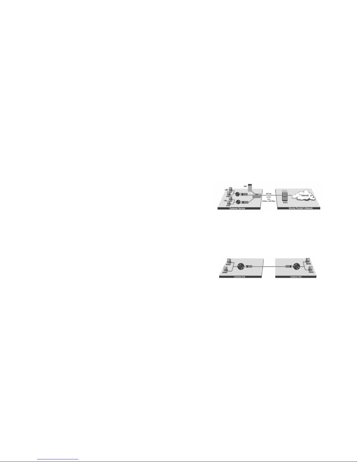
2.3 SUPPORTED APPLICATIONS
The Model 2094 provides an E1 network termination between E1
and Fractional E1 equipment and customer premises equipment (CPE)
such as a router. The Model 2094 can also be used as a high-speed
short haul modem for campus applications.
2.3.1 The 2094 as the Interface between the Telco and CPE
The Model 2094 provides the interface between an E1/Fractional
E1 multiplexer and a router or switch (See below).
2.3.2 The 2094 as a High-Speed Short Range Modem
The Model 2094 can also be installed into high-speed campus
applications. In this application, a pair of Model 2094 units operate as
short range modems (See below).
6
Model 2094
Model 2094
Page 5
Switch SW1: Line Coding
Use Switch SW1 to control the Network Line Coding options. Set
these options to be the same as the Line Coding given to you by your
Service Provider. If you are using two Model 2094s together as short
range modems, set both units to HDB3.
SW4 Line Framing & Coding
Off HDB3
On AMI
Line Coding Options:
High Density Bipolar 3 (HDB3): In HDB3 coding, the transmitter
deliberately inserts a bipolar violation when excessive zeros
in the data stream are detected. The receiver recognizes
these special violations and decodes them as zeros. This
method enables the network to meet minimum pulse density
requirements. Use HDB3 unless AMI is required in your
application .
Alternate Mark Inversion (AMI): AMI coding does not inherently
account for ones density. To meet this requirement, the user
should ensure that the data inherently meets pulse density
requirements.
8
3.0 CONFIGURATION
The Model 2094 features configuration capability via hardware
switches or a software control port. This section describes all possible
hardware and software switch configurations of the Model 2094.
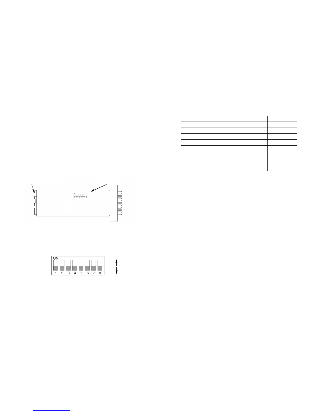
3.1 DIP SWITCH CONFIGURATION
The Model 2094 has eight internal DIP switches that allow configuration for a wide range of applications. The eight switches are
accessed by opening the plastic case with a small screwdriver. Figure
1 (below) shows the location of the DIP switches on the bottom of the
printed circuit board.
The Model 2094 DIP switches (Switches SW1 - SW8) can be configured as either “On” or “Off”. Figure 2 (below) shows the orientation
of the DIP switches with respect to ON/OFF positions.
Default positions for Switches SW1-SW8 are shown in the table on
the following page. Descriptions of each switch follow the table.
7
Figure 1. Model 2094 bottom view, showing location of DIP switches
DIP Switches
OFF
ON
Figure 2. Close up of DIP switches showing ON/OFF positions.
The switch is shown in the Off position.
ON
OFF
Software Configuration Port
SWITCH SET SUMMARY TABLE
Position Function Factory Default Selected Option
SW1 Line Coding Off HDB3
SW2 CAS Multiframe Off Disabled
SW3 CRC-4 Multiframe Off Disabled
SW4 Clock Mode Off Network
SW5 DTE Rate Off
SW6 DTE Rate Off
SW7 DTE Rate Off
SW8 DTE Rate Off
2.048 Mbps
Clear
Channel
}
Page 6
CLOCK MODES
Network Clock Transmitter timing is derived from the received line
signal.
Internal Clock Transmitter clock is derived from an internal clock
source.
External Clock Transmitter timing is derived from the local DTE
device. Valid only in unframed mode.
Note: When using the 2094 as a high-speed short range modem, one
unit of the link must be configured in either internal or external clock,
and the other end must be configured for network clock mode.
Switches SW5, SW6, SW7, and SW8
Use Switches SW5, SW6, SW7, and SW8 to set the DTE data rate.
SW5 SW6 SW7 SW8 Speed
Off Off Off Off Clear Channel (2.048Mbps)
On Off Off Off 64kbps
Off On Off Off 128kbps
On On Off Off 192kbps
Off Off On Off 256kbps
On Off On Off 384kbps
Off On On Off 512kbps
On On On Off 640kbps
Off Off Off On 768kbps
On Off Off On 1024kbps
Off On Off On 1280kbps
On On Off On 1536kbps
Off Off On On 1600kbps
On Off On On 1920kbps
Off On On On 1984kbps
On On On On invalid
10
UNFRAMED (G.703)
SW3 SW4 Clock Mode
Off Off Network (Default)
Off On Internal
On On External
On Off Network
Switch SW2: CAS Multiframe
The Channel Associated Signaling (CAS) multiframe uses Timeslot 16
(TS16) to send multiframe (MF) alignment data. In CAS MF, a multiframe is defined as 16 frames, where a frame consists of 32 64kb/s
timeslots, numbered 0 to 31. TS16 of the first frame in the MF contains
the CAS MF alignment word in the upper four bits. The alignment word
is always 0000 (binary). The 2094 does not perform any signaling in
TS16 other than to insert the MF alignment word, in order to maintain
MF alignment. When CAS MF is disabled, the unit transmits user data
in TS16; therefore, up to 31 channels are available for user data. When
it is enabled, TS16 is not available to the user. In this case, the user
can use up to 30 channels for data. CAS MF can be used with CRC-4
MF or by itself. When enabled, both units must employ CAS MF; if one
unit is set for CAS MF, and the other is not, the one using CAS MF will
detect a loss of sync.
SW2
Option
Off Disabled
On Enabled
Switch SW3 & SW4: CRC-4 Multiframe/Clock Mode
In framed mode, SW3 is used for CRC-4 MF. CRC-4 Multiframe uses
Time Slot zero to carry CRC-4 information. It operates independently of
CAS MF. When CRC-4 is enabled, the unit monitors the incoming data
stream for CRC-4 errors. It transmits CRC-4 error counts to the transmitting unit. Excessive errors may cause loss of frame or loss of sync.
If CRC-4 MF is used, both units must be set for set for CRC-4 MF.
Otherwise, the one using CRC-4 MF will detect loss of sync.
In unframed mode, SW3 is used to along with SW4 to determine the
clock mode. In unframed mode, the model 2094 can be set to network,
internal or external clock mode.
In framed mode SW4 is used alone to determine the 2094 transmitter
timing. In framed mode the 2094 can be set to Network or Internal
clock.
The following charts represent both cases.
9
MULTIFRAME(G.704)
SW3 CRC-4 MF SW4 Clock Mode
On On Off Network
Off Off On Internal
Page 7

NOTE: When the data rate is set to 2.048Mb/s, then the unit is
forced into G.703 mode, and it transmits user data on all 32 timeslots. There is no framing information; therefore, the CAS MF
(SW2) switch is ignored. SW3 is defaulted to clock mode. In all
other rate settings, the unit employs G.704 framing; TS0 is
reserved for signaling.
3.2 SOFTWARE CONFIGURATION
The Model 2094 features a menu-driven command system that
allows you to monitor/configure its operating parameters. Follow the
instructions below to configure the Model 2094 using the software
switches:
1) Plug the 9-pin male end of the cable to your terminal or computer’s DB-9 serial port and start up the terminal emulator
software if necessary. Plug the miniature stereo plug into the
rear of the unit. The small recessed jack on the right side of
the unit is the control port jack.
NOTE: If your terminal uses a DB-25 connector, please use
a DB-9 to DB-25 Adapter to connect to the cable (See Model
18PC-M).
2) Power up the terminal and set its RS-232 port as follows:
9600 Baud
8 data bits, 1 stop bit, no parity
Local echo off
ANSI or VT-100 emulation
Xon/Xoff software flow control enabled
3) Here is an example of a terminal emulator setup session. In
normal font are the various parameter types. In bold type are
the values that should be used for best results. Your terminal
program’s setup screen may differ from this one:
11
4) When the unit is first turned on, the terminal screen may
appear blank. Press the [Enter] key. If your serial connection
is good, then the unit will immediately display a password
prompt. The following message will appear in the middle of
the screen:
5) Type in the password and press [Enter]. The factory default
password for the unit is:
patton
NOTE: The password is case sensitive. If the entry is incorrect, the password screen will clear and prompt you again for
the correct password. The password you enter will not be
shown. For security, asterisks will be displayed for each letter
you type. The maximum length of the password, which can
include any character the terminal can generate, is 16 characters.
6) The Model 2094 will then display the Main Menu screen.
12
Baud rate: 9600 Parity: None Data Length: 8 Stop Bits: 1
Default terminal type: VT100
Local Echo: Off
Add Line Feeds after CRs: Off
Received Backspace Destructive: On
Backspace key sends: BS
XON/XOFF software flow control: On
CTS/RTS hardware flow control: Off
DSR/DTR hardware flow control: Off
Patton Electronics
Menu Management
Enter Password: _
Page 8

3.2.1 Introduction to Main Menu
After entering the password, you may access all of the system’s
functions and parameters. The Main Menu looks like this:
HELPFUL HINTS
1. To make a selection, key the highlighted letter that corresponds to a menu selection.
2. To execute the selection, type [Enter/CR]
3. Select g Save Changes from Main Menu after making modifications to any Model 2094 parameter. Otherwise, changes
will be lost when the Model 2094 is turned off.
13
The Main Menu options are briefly described below.
System Configuration options allow you to change various
aspects of the Model 2094’s operation, e.g., framing, line coding, and aggregate bandwidth.
System Diagnostics/Statistics options allow you to monitor
the network performance, initiate V.54 loops, local loops, and
send test patterns. Network performance parameters are
updated once a second, giving you the ability to quickly determine if there is a problem.
Unit Options allow you to customize the Model 2094 for your
location. You can change the default header names to give
each unit a unique name and password. Also, you can reset
the unit to its default settings without the manual. It also has a
Service Information screen in case you need technical assistance from Patton.
Save Changes Once you have configured the unit to your
satisfaction, you can save the changes permanently by executing the Save Changes command. This will update the units
configuration and save all the parameters to permanent memory.
Logoff For security, log off the control menu by executing the
Logoff command. This will blank the screen until an [Enter]
key is pressed.
14
d
a
b
c
d
e
Page 9

3.2.2 System Configuration
The System Configuration menu looks like this:
The System Configuration options are described below:
Line Format: G.703
(default)
Options: G.703, G.704
G.703: G.703 is unframed, 2.048Mb/s. In this case, the DTE rate
is equal to the line rate at the network interface (NI). CAS MF
and CRC-4 are disabled.
G.704: G.704 reserves TS0 for signaling and frame alignment.
Maximum data rate depends on whether CAS MF is enabled
or not.
15
16
Line Coding: HDB3
(default)
Options: HDB3, AMI
HDB3: In this line coding, the transmitter substitutes a deliberate
bipolar violation when excessive zeros in the data stream are
detected. The receiver recognizes these special violations
and decodes them as zeros. This method enables the network to meet minimum pulse density requirements. Unless
AMI is required in your application, HDB3 should be used
whenever possible.
AMI: Alternate Mark Inversion defines a pulse as a "mark,” a
binary one, as opposed to a zero. In a E1 network connection, signals are transmitted as a sequence of ones and
zeros. Ones are sent as pulses, and zeros are sent as
spaces, i.e., no pulse. Every other pulse is inverted from the
previous pulse in polarity, so that the signal can be effectively
transmitted. This means, however, that a long sequence of
zeros in the data stream will cause problems, since the NTU
receiving the signal relies on the signal to recover the 2.048
Mb/s clock. If you must use AMI, you should ensure that the
data terminal equipment connected to the unit provides a minimally acceptable pulse density. For this reason, there are
advantages to using HDB3 instead.
a
b
Page 10

Clocking: Network
(default)
Options: Network, Internal, External
Network: This is the most commonly used setting when connect-
ing to a carrier’s network. In this mode, the unit recovers the
clock from the received signal and uses it to transmit data. In
this way the unit remains synchronized to a master clock. In
campus applications, one of the units must be set to Internal
clock, and the other end is set to Network clock. At all times,
there must be only one clock source. Otherwise, clock slips,
framing errors, and bit errors may occur.
Internal: This is commonly used in campus applications, where
the unit is not connected to the public telephone network
directly. In this mode, the unit uses the on-board oscillator as
the transmit clock source.
External: This is a special mode that can only be used with the
Unframed format. In this mode, the unit requires a 2.048 Mhz
clock signal from the DTE via the external clock pin on the
DTE interface connector. Most applications will use Network
or Internal clock modes.
CRC-4 Setting: Disabled
(default)
Options: Enabled, Disabled
CRC-4 Multiframe: CRC-4 Multiframe uses TS0 to carry CRC-4
information. It operates independently of CAS MF. When
CRC-4 is enabled, the unit monitors the incoming data stream
for CRC-4 errors. It transmits CRC-4 error counts to the transmitting unit . Excessive errors may cause loss of frame or loss
of sync. If CRC-4 MF is used, both units must be set for CRC4 MF; otherwise, the one using CRC-4 MF will detect a loss of
sync.
17
CAS MF Setting: Disabled
(default)
Options: Enabled, Disabled
CAS MF: CAS multiframe uses Timeslot 16 (TS16) to send multi-
frame (MF) alignment data. In CAS MF, a MF is defined as 16
frames, where a frame consists of 32 64kb/s timeslots, numbered 0 to 31. TS16 of the first frame in the MF contains the
CAS MF alignment word in the upper four bits. The alignment
word is always 0000 (binary). The 2094 does not perform any
signaling in TS16 other than to insert the MF alignment word,
in order to maintain MF alignment. When CAS MF disabled,
the unit transmits user data in TS16; therefore, up to 31 channels are available for user data. When it is enabled, TS16 is
not available to the user. In this case, the user can use up to
30 channels for data. CAS MF can be used with CRC-4 MF or
by itself. When enabled, both units must employ CAS MF; if
one unit is set for CAS MF, and the other is not, the one using
CAS MF will detect a loss of sync.
V.54 Loops: Enabled
(default)
Options: Enabled, Disabled
This is a special in-band loopback facility that sends a special pseudorandom pattern over the data stream. This is the only loopback that the
unit can initiate. This is useful for campus applications when you need
to put a remote unit in loopback. The unit responds to the V.54 loopback command, and the whole process takes only a few seconds to
complete. When V.54 Loopback is disabled, the unit will not be able to
send or respond to V.54 loopback commands. The duration of the loopback is limited by the loopback timeout setting. While V.54 is being
activated, user data is overwritten.
Default Config Source: Switch (default)
Options: EEPROM, Switch
The Model 2094 can be initialized via the configuration in the on-board
permanent memory (EEPROM) or via the internal DIP switches
(Switch). Once the unit is powered up, you may change the settings
through the control port or the DIP switches. When you make changes
through the control port, no changes will take place or be saved to permanent memory until you Save Changes (Main Menu option "d" +
[Enter]). When you make changes through the switches, all changes
are made immediately.
18
d
f
i
j
g
Page 11

3.2.3 System Diagnostics
The System Diagnostics/Statistics screen looks like this:
NOTE: This screen is updated once per second.
The System Diagnostics/Statistics options and functions are described
below.
Local Loop Idle
(default)
The Local Loop is a bi-lateral loopback in which the data from the local
DTE and the data from the remote unit are looped back to their respective sources (See Section 5.3). Activate this loop to test the each of
the DTE’s connection to the Model 2094.
The Local Loop test has four states:
Idle No user-controlled loopbacks are active.
LL The Model 2094 is in local loopback mode.
Off The Model 2094 is in remote loopback mode or sending
a pattern. Local loopback is disabled.
LocP The Model 2094 is in local loopback mode, and is send-
ing a test pattern.
20
If you do not have a terminal, you may force the unit to use the DIP
switches as the default configuration source by turning off the unit, setting all the DIP switches to the ON position, then powering on the unit.
This will cause the unit to enter a special mode. Then turn off the unit
and change the switch settings to the desired settings. When you turn
the unit on again, the unit will be set up with the selected switch settings.
DS0 Channel Configuration Menu [ Bandwidth/# Channels =
2,048k/na]
(default)
The Channel Configuration Menu has a sub-menu that looks
like this:
You may configure the Model 2094 to operate with any combination of
active and inactive DS0 channels in this screen. When you execute the
Save Changes command, the selected settings will be saved to permanent memory, and the system will be updated to operate with the new
channel settings.
NOTE: In Unframed format, the Bandwidth Selected will display
“2.048k,” and the Total Channels will display “na.” When using the
DIP switches to set the bandwidth, the starting channel is always
channel 1 or 0.
19
n
a
Page 12

22
21
Remote Loop Idle
(default)
The Remote Digital Loopback (RDL) test checks the performance
of both the local and remote Model 2094s, as well as the communication link between them. Data from the local DTE is sent across the
entire communication circuit and looped back to the local DTE.
The Model 2094 Initiating a RDL can be in one of the following
states:
Idle No user-controlled loopbacks are active.
TxPr The Model 2094 is sending the preparatory phase pattern
lasting for approximately 2 - 5 seconds.
WtAk The Model 2094 is waiting for an acknowledgement from
the remote unit. If the remote unit does not respond, the
WtAk message will remain on the screen.
RxAk The Model 2094 has received an acknowledgement from
the remote unit.
Tout The Model 2094 is waiting before entering the Remote
Loopback test mode.
TM The Model 2094 has successfully negotiated the Remote
Loopback test and is in control of the remote unit. You
may send a test pattern at this point by pressing:
c <spacebar>
TxTr The Model 2094 is sending a Terminate Loopback mes-
sage to the remote unit. If the remote unit does not
respond, the local unit will return to the Idle state.
Tx1s If the remote Model 2094 responds to the local Model
2094’s terminate loopback request, the local unit then
sends an all ones pattern before returning to the Idle
state
TxP The Model 2094 is sending a test pattern while in Test
Mode
IdlP The Model 2094 is sending a test pattern in place of data.
The Model 2094 is not in test mode.
The Model 2094 receiving a RDL can be in one of the following states:
RxPr The Model 2094 is receiving a preparatory pattern.
Sack The Model 2094, upon receiving a preparatory pattern,
sends an acknowledgement message.
RL The Model 2094 is in remote loopback mode.
RxTr The Model 2094 is receiving a terminate loopback mes-
sage.
WE1s The Model 2094 is waiting for a sequence of all ones and
will time out if it does not receive it.
IdleP The Model 2094 is sending a QRSS, 511, or 2047 pat-
tern.
Off The Model 2094 is in local loopback.
Test Pattern Idle
(default)
Options: Idle or Sending
To send a pattern, press the ‘c’ key and press <spacebar> to send the
test pattern. The “OK” message indicates the received test pattern is
error-free. The “BE” message indicates errors in the received pattern.
You may also hear a beep (from your terminal) once a second as long
as the unit detects a bit error in the pattern.
Idle Indicates that Model 2094 is not sending a pattern.
Sending
Indicates that Model 2094 is sending a pattern.
Error Insertion Off
(default)
Options: On, Off
You may inject intentional errors into the test pattern by turning Error
Insertion ON. The Error (ERR) LED will blink once per second.
Selected Pattern
Options: QRSS, 511, or 2047
b
d
c
e
Page 13

23 24
Use this option to select the test pattern used to test the link.
NI STATUS
The Network interface (NI) status is shown
in the middle of the Diagnostics/Statistics
screen. The brackets are empty when the
link is operating normally. Only one error
message is provided
Receiver Carrier Loss [RCL] occurs when 255 consecutive zeros
have been detected at the network interface. RCL clears when a pulse
is detected.
Current DIP Switch Settings
The Switch settings are displayed here to
facilitate troubleshooting your unit without
opening up the unit first.
3.2.4 Unit Options
The Unit Options screen looks like this (factory default):
Header Line 1 & Header Line 2
Headers 1 and 2 are provided for easy identification of your unit after
installation. You may want to give each unit a unique name via the
header lines to help distinguish one unit from another. You can enter a
header up to 40 letters long. Two lines provide 80 letters for your use.
That’s a lot of flexibility!
Password
The Password facility provides security by allowing only those who
know the correct password to configure the unit via the control port.
You can still configure the unit via the DIPswitches. The password can
be up to 16 characters long, with no restriction on the combination of
characters you can use, so be sure to remember the password. The
password is case sensitive. If you lose your password, you will lose the
ability to access the unit via the control port.
RCL
a
b
c
Page 14

25 26
Loop Timeout
The Loop Timeout setting can be set to one of the following:
00:05 = five minutes
00:10 = ten minutes
00:15 = fifteen minutes
00:30 = thirty minutes (default setting)
00:45 = forty-five minutes
01:00 = one hour
01:30 = 90 minutes
02:00 = two hours
03:00 = three hours
NEVER = forever—the unit will remain in loopback without user
intervention.
Set to Default Configuration
You may set the Model 2094 to its factory default configuration, except
for the header lines and the password, by executing the Set to Default
Configuration command.
Service Information
If you need to contact us for help, you can view the Service Information
screen. Here is what it looks like:
4.0 INSTALLATION
The Model 2094 is equipped with DTE, network, and power interfaces.
This section briefly describes connection to each.
4.1 DTE INTERFACE CONNECTION
The DTE interface is a V.35 DCE presented as an M/34 male connector. This interface is designed to plug directly into a DTE interface
(See Appendix D for V.35 interface pin assignments).
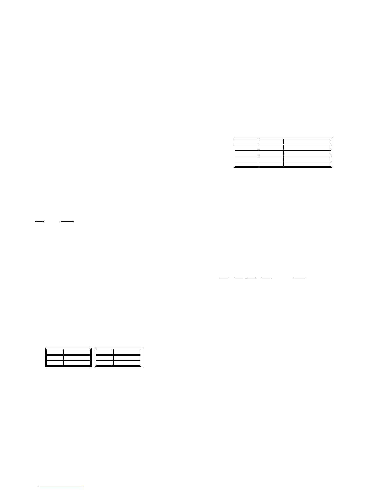
4.2 NETWORK INTERFACE CONNECTION
The Network Line Interface is an eight position keyed modular jack
configured as a RJ-48C. This interface will need to be configured to
match the line parameters (i.e. framing, line coding, etc.) supplied by
the central office.
NOTE: If the Model 2094 is being used for private short range
modem applications, the twisted pair cable connected to its port
will need to be a cross-over cable. See Appendix D for Interface
pin assignments.
d
f
g
Figure 3. Model 2094 twisted pair line interface.
1 RX Data (TIP)
2 RX Data (RING)
3 (no connection)
4 TX Data (TIP)
5 TX Data (RING)
6 (no connection)
7 (no connection)
8 (no connection)
1
2
3
4
5
6
7
8
Page 15

27 28
4.3 POWER CONNECTION
The Model 2094 offers three ways to supply external power: AC
power, DC power and interface power.
4.3.1 Using the AC Power Supply (100-240VAC)
The Model 2094 uses a 5VDC, 2A universal input 100-240VAC,
power supply (center pin is +5V). The universal input power supply is
equipped with a male IEC-320 power entry connector. This power supply connects to the Model 2094 by means of a barrel jack on the rear
panel. There are a variety of international power cords available for
the universal power supply. The Model 2094 powers up as soon as it
is plugged into an AC outlet–there is no power switch.
4.3.2 Supplying DC Power
The 36-60 VDC DC to DC adapter is supplied with the DC version
of the Model 2094. The black and red leads plug into a DC source
(nominal 48VDC) and the barrel power connector plugs into the barrel
power supply jack on the 2094.
4.3.3 Supplying Power via pin KK
You may also supply DC power directly to pin KK of the V.35 interface. DC Power supplied to pin KK must be +5VDC ± 5%, 300mA
minimum.
NOTE: Model 2094 is factory configured to accept power from the
enclosed DC wall adapter (See Sections 4.3.1 and 4.3.2 above).
If you wish to supply power via pin KK on the interface, you must
change the setting of the
power supply jumper
on the printed circuit board See Appendix E. All power sources must be SELV
(Circuit, Safety Extra Low Voltage) specified. (See CENELEC
EN60950, Section 1.2.8.5)
5.0 OPERATION
Once the Model 2094 is installed and configured properly it is ready
to place into operation. This section describes the function of the LED
indicators, and the use of the loopback and pattern test modes.
5.1 LED DESCRIPTIONS
The Model 2094 is equipped with seven LED indicators that monitor the status of communication. Figure 4 (below) shows the location
of the LEDs on the Model 2094 front panel.
TXD When the unit sends a one, the TXD LED is
turned on. When it sends a zero, the TXD
LED is turned off. Moreover, the TXD LED
is active only in active DS0 channels. In
inactive channels, the TXD LED is off.
RXD When the unit receives a one, the RXD LED
is turned on. When it receives a zero, the
RXD LED is turned off. Moreover, the RXD
LED is active only in active DS0 channels.
In inactive channels, the RXD LED is off.
RXD
LOS
ALM
ERR
T/L
PWR
TXD
Model 2711
Figure 4. Top of Model 2094, Showing LED Indicators
Model2094
To Power
Supply Jack
To -48VDC
Source
-Vin
+Vin
SWITCHING POWER SUPPLY
MODEL : SYD1106-0505
INPUT : 36-60V 0.2A MAX
OUTPUT : +5V 1.0A
OUTPUT POWER : 5W MAX
S/N: G01234567890
MADE IN CHINA BY SUNNY
Black lead (-V)
Red lead (+V)
Barrel power connector
Page 16

29
30
LOS The Loss of Sync LED lights when the unit
loses synchronization with the incoming signal. This may happen when there is a framing mismatch or a loss of signal. In
unframed mode, the LOS LED monitors the
status of the transmit clock.
ALM The alarm LED indicates the presence of a
AIS or RAI, or Out of Frame condition. The
ALM LED will blink on every half-second.
Alarms may occur due to:
•
Loss of Synchronization
• Loss of Frame
• AIS (Blue Alarm)
• RAI (Yellow Alarm)
ERR The error LED indicates various error condi-
tions, including framing bit errors, excessive
zeros, controlled slips, severe errors, or bit
errors (when sending V.52 test patterns).
When sending a test pattern, the LED will
remain lit if the unit does not receive the
identical pattern. When it receives the correct pattern, the LED will turn off. If error
insertion is on, the LED will blink once a
second if everything is operating properly.
TST The test indicator LED blinks with a specific
pattern depending on the type of test mode.
When the unit is in local analog loop, the
LED will blink on briefly. When the unit is in
remote loop, the TST LED will blink off
briefly. When the unit is sending a test pattern or is putting the remote unit into V.54
loopback, the TST LED will stay on. These
are the test modes:
• V.54 Loopback & V.52 Patterns
PWR The power indicator LED will remain lit while
the unit is powered. It turns off when the
unit is not powered.
5.2 LOOP (V.54 & TELCO) DIAGNOSTICS
The Model 2094 offers three V.54 loop diagnostics. Use these
diagnostics to test the NTU and any communication links. These tests
can be activated via the software control port (See Section 3.2.3
System Diagnostics) or via signals on the serial port interface.
5.2.1 Operating Local Loopback (LL)
The Local Loopback (LL) test checks the operation of the local
Model 2094, and is performed separately on each unit. Any data sent
to the local Model 2094 in this test mode will be echoed (returned)
back to the user device (i.e., characters typed on the keyboard of a terminal will appear on the terminal screen).
To perform a LL test, follow these steps:
1. Activate LL. This may be done in one of two ways:
a. Enter Local Loop from the System
Diagnostics/Statistics menu and toggle the <Spacebar>
until “LL” appears next to the Local Loop option.
b. Activate the “LL” signal on the DTE. If you are not sure
which lead is the “LL” signal, please refer to Appendix D.
2. Verify that the data terminal equipment is operating properly
and can be used for a test.
3. Perform a V.52 BER (bit error rate) test as described in
Section 5.3.3. If the BER test equipment indicates no faults,
but the data terminal indicates a fault, follow the manufacturer’s checkout procedures for the data terminal. Also, check
the interface cable between the terminal and the Model 2094.
5.2.2 Operating Remote Digital Loopback (RDL)
The Remote Digital Loopback (RDL) test checks the performance
of both the local and remote Model 2094, as well as the communication link between them. Any characters sent to the remote Model 2094
in this test mode will be returned back to the originating device (i.e,
characters typed on the keyboard of the local terminal will appear on
the local terminal screen after having been passed to the remote
Model 2094 and looped back).
a
a
Page 17

31 32
To perform an RDL test, follow these steps:
1. Activate RDL. This may be done in two ways:
a. Enter Remote Loop from the System
Diagnostics/Statistics menu and toggle the <Spacebar>
until “TM” appears next to the Remote Loop option.;
b. Activate the “RL” signal on the DTE. If you are not sure
which lead is the “RL” signal, please refer to Appendix D.
2. Perform a bit error rate test (BERT) using the internal V.52
generator (as described in Section 5.3), or using a separate
BER Tester. If the BER test indicates a fault, and the Local
Line Loopback test was successful for both NetLink™s, you
may have a problem with the twisted pair line connection.
5.3 BIT ERROR RATE (V.52) DIAGNOSTICS
The Model 2094 offers three V.52 Bit Error Rate (BER) test patterns. These test patterns may be invoked along with the LAL and
RDL tests to evaluate the unit(s) and the communication links.
When a 511, 2047, or QRSS test is invoked, the Model 2094 generates a pseudo-random bit pattern of 511 bits, 2047 bits or 220bits,
respectively, using a mathematical polynomial. The receiving model
2904 then decodes the received bits using the same polynomial. If the
received bits match the agreed upon pseudo-random pattern, then the
Model 2094(s) and the communication link(s) are functioning properly.
511 Initiates a built-in 511 bit pseudo-random
pattern generator and detector.
2047 Initiates a built-in 2047 bit pseudo-random
pattern generator and detector.
QRSS Initiates a built-in 2
20
bit pseudo-random
pattern generator and detector.
To perform a V.52 test, follow these steps:
1. Activate the local loopback or remote loopback diagnostic.
2. Activate the test pattern. This may be done in one of two
ways:
a. Enter Selected Pattern from the System
Diagnostics/Statistics menu and toggle the <Spacebar>
until the desired test pattern appears.
b. Enter Test Pattern and toggle the <Spacebar> to
send the selected pattern.
c. One of two result codes will appear to the right of the
Test Pattern listing:
OK Indicates that the received test pattern is error-free.
BE Indicates that there are errors in the test pattern (to
deliberately insert errors in the pattern, toggle
Error Insertion to ON).
b
b
e
d
c
c
Page 18

33 34
APPENDIX A
PATTON MODEL 2094
SPECIFICATIONS
Network Data Rate: 2.048 Mbps
Network Connector: RJ-48C
Nominal Impedance: 120 ohm (75 ohm available when using
Patton Model 460 Balun)
DTE Interface: V.35 (DCE Orientation) on Male M/34
Line Coding: Selectable AMI or HDB3
Line Framing: G.703 (Unframed) or G.704/G.732
(Framed)
CAS Multiframing: Selectable On or Off
CRC-4 Multiframing: Selectable On or Off
Clocking: Internal, External, or Receive Recover
DTE Data Rates: 64, 128, 192, 256, 384, 512, 640, 768,
1024, 1280, 1536, 1600, 1920, 1984,
2048 kbps
Time Slot Rate: 64 kbps
DS0 Start Position: Arbitrary
DS0 Mapping Position: Contiguous or Arbitrary
Diagnostics: V.54 Loopback; V.52 Patterns: 511,
2047, and QRSS
Indicators: Power, Transmit Data, Receive Data,
Alarm, Loss of Sync, Test Mode, Error
Configuration: 8-Position DIP Switch and RS-232
Control Port
Power Supply: 100-240VAC, 50-60Hz, 0.4A
Humidity: Up to 90% non-condensing
Temperature: 0 to 70
o
C
Dimensions: 9.0 x 5.3 x 2.0 cm (3.5”L x 2.1”W x
0.78”H)
APPENDIX B
PATTON MODEL 2094
CABLE RECOMMENDATIONS
The Patton Model 2094 has been performance tested by Patton
technicians using twisted-pair cable with the following characteristics:
W
ire Gauge Capacitance Resistance
19 AWG 83nf/mi or 15.72 pf/ft. .0163 Ohms/ft.
22 AWG 83nf/mi or 15.72 pf/ft. .0326 Ohms/ft.
24 AWG 83nf/mi or 15.72 pf/ft. .05165 Ohms/ft.
To gain optimum performance from the Model 2094 , please keep
the following guidelines in mind:
•
Always
use twisted pair wire—this is not an option.
• Use twisted pair wire with a capacitance of 20pf/ft or less.
• Avoid twisted pair wire thinner than 26 AWG (i.e. avoid AWG
numbers higher than 26)
• Use of twisted pair with a resistance greater than the above
specifications may cause a reduction in maximum distance obtainable. Functionality should not be affected.
• Many environmental factors can affect the maximum distance
obtainable at a particular site. Use the above data rate/distance
table as a
general guideline only.
Model 2703B Distance Table - Km (Miles)
Data Rate Wire Gauge
(kbps) .7mm (22) .5mm (24)
2048 1.2 (.76) 1.5 (.95)
Page 19

35 36
APPENDIX C
PATTON MODEL 2094
FACTORY REPLACEMENT PARTS
AND ACCESSORIES
Patton Model #
Description
2094/CM/UI.....................V.35 to E1 Converter (V.35 M/34 Male,
UI)
10 - 09F...........................6 Foot Control Port Cable, 25 mm to
DB9F
08055DCUI......................Universal Input Power Supply
10-CISCO-V35FT-1.........Cable, V35 (M/34) Female To LFH60
Male
07M2094 .........................User Manual
APPENDIX D
PATTON MODEL 2094
INTERFACE PIN ASSIGNMENTS
RJ-48C E1 Network Interface
(RJ-48S Female Modular Jack)
Pin # Signal
1 RX Data (TIP)
2 RX Data (RING)
4 TX Data (TIP)
5 TX Data (RING)
Page 20

37
38
APPENDIX D
(continued)
PATTON MODEL 2094
INTERFACE PIN ASSIGNMENTS
M/34 Connector, Terminal Interface
Pin # Signal
A GND (Earth Ground/Shield)
B SGND (Signal Ground)
D CTS (DCE Source)
E DSR (DCE Source, Always On)
F CD (DCE Source)
L LL (Local Loop, DTE Source)
M TM (Test Mode Indicator (DCE Source)
N RL (Remote Loop, DTE Source)
P TD (Transmit Data +, DTE Source)
R RD (Receive Data +, DCE Source)
S TD/ (Transmit Data -, DTE Source)
T RD/ (Receive Data -, DCE Source)
U SCTE (Transmit Clock+, DTE Source)
V RC (Receiver Clock +, DCE Source)
W SCTE/ (Transmit Clock-, DTE Source)
X RC/ (Receiver Clock -, DCE Source)
Y TC (Transmitter Clock +, DCE Source)
AA TC/ (Transmitter Clock -, DCE Source)
KK Aux. Power Input (+5VDC @ 300mA)
APPENDIX E
PATTON MODEL 2094
POWER SUPPLYINTERFACE
Via Main 5VDC power jack (J1)
Center Pin: 5VDC @ 300 mA
Outer Barrel: Ground
Jumper Position for Power via DC Power Jack (default):
Via Auxiliary Power Supplied to Pin KK on V.35 connector
DC Power supplied to pin KK must be 5VDC ± 5%, 300mA minimum.
Jumper Position for Power via Pin KK:
NOTE: Model 2094 is factory configured to accept power from
the enclosed DC wall adapter (See Sections 4.3.1 and 4.3.2
above). If you wish to supply power via pin KK on the interface,
you must change the setting of the
power supply jumper
on the
printed circuit board. All power sources must be SELV (Circuit,
Safety Extra Low Voltage) specified. (See CENELEC EN60950,
Section 1.2.8.5)
 Loading...