

Page 1
USER
MANUAL
SALES OFFICE
(301) 975-1000
TECHNICAL SUPPORT
(301) 975-1007
http://www.patton.com
Part# 07M2086-C
Doc# 055051UC
Revised 05/11/99
MODEL 2086 Series
Optically Isolated
RS-232 to RS-485
Interface Converter
CERTIFIED
An ISO-9001
Certified Company
Page 2

1 2
1.0 WARRANTY INFORMATION
Patton Electronics warrants all Model 2086 Series components to
be free from defects, and will—at our option—repair or replace the
product should it fail within one year from the first date of shipment.
This warranty is limited to defects in workmanship or materials,
and does not cover customer damage, abuse or unauthorized modification. If this product fails or does not perform as warranted, your sole
recourse shall be repair or replacement as described above. Under no
condition shall Patton Electronics be liable for any damages incurred
by the use of this product. These damages include, but are not limited
to, the following: lost profits, lost savings and incidental or consequential damages arising from the use of or inability to use this product.
Patton Electronics specifically disclaims all other warranties,
expressed or implied, and the installation or use of this product shall be
deemed an acceptance of these terms by the user.
1.1 RADIO AND TV INTERFERENCE
The Model 2086 Series generates and uses radio frequency energy, and if not installed and used properly—that is, in strict accordance
with the manufacturer's instructions—may cause interference to radio
and television reception. The Model 2086 Series has been tested and
found to comply with the limits for a Class A computing device in accordance with the specifications in Subpart J of Part 15 of FCC rules,
which are designed to provide reasonable protection from such interference in a commercial installation. However, there is no guarantee that
interference will not occur in a particular installation. If the Model 2086
Series does cause interference to radio or television reception, which
can be determined by disconnecting the RS-232 interface, the user is
encouraged to try to correct the interference by one or more of the following measures: moving the computing equipment away from the
receiver, re-orienting the receiving antenna and/or plugging the receiving equipment into a different AC outlet (such that the computing
equipment and receiver are on different branches).
1.2 CE NOTICE
The CE symbol on your Patton Electronics equipment indicates
that it is in compliance with the Electromagnetic Compatibility (EMC)
directive and the Low Voltage Directive (LVD) of the Union European
(EU). A Certificate of Compliance is available by contacting Technical
Support.
1.3 SERVICE
All warranty and nonwarranty repairs must be returned freight prepaid and insured to Patton Electronics. All returns must have a Return
Materials Authorization number on the outside of the shipping container.This number may be obtained from Patton Electronics Technical
Services at:
Tel: (301) 975-1007
Email: support@patton.com
www: http://www.patton.com
Patton Electronics' technical staff is also available to answer any
questions that might arise concerning the installation or use of your
Patton Model 2086 Series. Technical Service hours: 8AM to 5PM
EST,Monday through Friday.
NOTE: Packages received without an RMA number will not be
accepted.
Page 3
3 4
2.0 GENERAL INFORMATION
Thank you for your purchase of this Patton Electronics product.
This product has been thoroughly inspected and tested and is warranted for One Year parts and labor. If any questions or problems arise
during installation or use of this product, please do not hesitate to contact Patton Electronics Technical Support at (301) 975-1007.
2.1 FEATURES
• Operates asynchronously, point to point or multipoint,
over 2 or 4 wires
• Up to 32 multipoint device drops in a polling environment
• Data rates to 115.2 Kbps
• Passes transmit & receive data
• Operates off 5V power supply
• Operates without “echo”
• Driver controlled as “constantly on”, “controlled by RTS”, or
“controlled by DTR”
• Compact size ( 3.8” x 2.10” x 0.8”)
• Twisted pair connection via strain relief, RJ-11 or RJ-45
• 2500 Vrms Optical Isolation
2.2 DESCRIPTION
The Model 2086 Series High Speed RS-232 to RS-485 Interface
Converter provides exceptional versatility in a compact package.The
Model 2086 Series supports asynchronous RS-232 data rates to 115.2
Kbps over one or two unconditioned twisted pair.
The Model 2086 Series can handle up to 32 terminal drops in a
multipoint polling environment. Carrier may be set to “constantly on” or
“controlled by RTS”, or “controlled by DTR” and the unit operates without “echo”.
The Model 2086 Series is equipped with a DB-25 for the RS-232
connection. Options for twisted pair connection include RJ-11, RJ-45,
or Terminal Block. 2500Vrms optical isolators provide isolation
between the RS-232 and RS-485 interfaces.
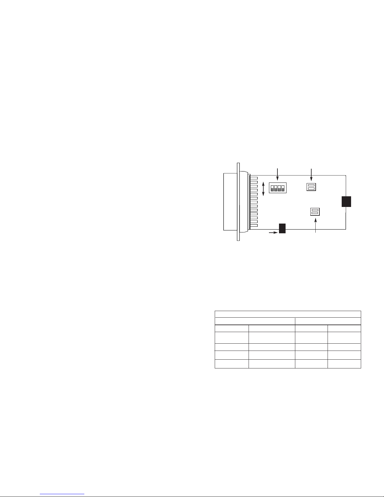
3.0 CONFIGURATION
The Model 2086 Series is configured using a four position DIP
switch and two headers.Figure 1 (below) shows the location of the DIP
switch and the two headers on the board.
3.1 DIP SWITCH CONFIGURATION
The DIP switches control the transmit/receive signals on the Model
2086 Series.The table below shows the default configuration of the
switches. Following the default table is a char t showing the different
switch and jumper combinations that the Model 2086 Series has to
offer.Also included in this section is a description of the switches.
+XMT- G -RCV+
ON
OFF
Figure 1. Top View of Model 2086 Series board, showing Dip switch and jumpers
A
A
B
B
DIP SWITCH
JP4
JP3
Power
DIP SWITCH DEFAULT SETTING TABLE
Position Function
S1 RTS Control
S2 DTR Control
S3
Reserved
S4 Transmitter Control
Default
Switch
Function
off
no RTS control
of transmitter
off
no DTR control
off
n/a
ON
Constantly ON
1
2
34
Page 4

5 6
KEY: ^ S1-1, S1-2, and S1-4: only one switch can be ON at any time.The
other two must be off.It is recommended that you, the user
disconnect (the model 2086 Series) while changing configurations.
* JP4A: If this jumper is off, only the RS-485 transmitter is controll-
ed by RTS or DTR.If this jumper is ON, both the RS-485 transmitter and receiver are controlled by RST or DTR. When the transmitter is off, the receiver will be ON, and similarly, when the transmit
ter is ON, the receiver is off.
** JP3A & JP3B: Both jumpers or either On or off. When the jumpers
are ON, the RS-485 transmitter and receiver are connected directly together.This will only function in HDX.When the jumpers are
off, the RS-485 transmitter and receiver are disconnected from
each other.This can be operated in either HDX or FDX, depending on the setting of JP4A.
Switch S1: RTS Control
When Switch S1 is in the On position, the DTE input signal RTS (Pin 4) is
used to control the transmitter of the Model 2086 Series. In this mode, when
RTS is high, the 2086 Series transmits data from the RS-232 port to the RS485 port. Switch S2 and S4 must be OFF position when Switch S1 is ON.
S1 Setting
On RTS Controls the Transmitter
Off RTS Control is OFF
Switch S2: DTR Control
When Switch S2 is in the ON position, the DTE input signal DTR (Pin 20)
is used to control the transmitter of the Model 2086 Series. In this mode, when
DTR is high, the 2086 Series transmits data from the RS-232 port to the RS485 port. Switches S1 and S4 must be OFF position when Switch S2 is
ON.
S2 Setting
On DTR Controls the Transmitter
Off DTR Control is OFF
Switch S3: Reserved
Switch S3 is reserved for future use and must remain in the OFF position.
Switch S4: Transmitter Control
When Switch S4 is in the OFF position, the input of RTS or DTR controls
whether the unit can send data (based on the configuration of switch S1 and
S2). In this setting, and when in the appropriate signal is high, the 2086 Series
can transmit data from the RS-232 port to the RS-485 port. When S4 is ON,
the 2086 Series transmitter is always enabled.
S4
Setting
On Constant Transmitter
Off Transmitter is controlled by RTS or DTR
3.2 JUMPER CONFIGURATION
Jumper straps JP3 and JP4 are used to control two-wire/four-wire,
half-duplex/full-duplex operation,and receive impedance, respectively.
*NOTE: Default Settings shown in bold italics
INTERFACE CARD STRAP SUMMARY TABLE
Strap Function ON Off
JP3A 2 Wire/4 Wire Mode 2 Wire
4 Wire*
JP3B 2 Wire/4 Wire Mode 2 Wire
4 Wire*
JP4A Half/Duplex Half Duplex
Full Duplex*
JP4B Impedance 120 Ohm
12K Ohm *
Transmission
S1-1^ S1-2^
S1-3
S1-4^
JP4A* JP4B JP3A & JP3B**
Mode RTS Control DTR Control
Reserved
always off
RS485 TX always ON
RS-485, FDX,
Transmitter is
always on
off off off ON off n/a off
RS-485, FDX,
Transmitter is
controlled by
RTS
ON off off off off n/a off
RS-485, FDX,
Transmitter is
controlled by
DTR
off ON off off off n/a off
HDX, 4-Wire
controlled by
RTS
ON off off off ON n/a off
HDX, 2-Wire
controlled by
RTS
ON off off off ON n/a ON
HDX, 4-Wire
controlled by
DTR
off ON off off ON n/a off
HDX, 2-Wire
controlled by
DTR
off ON off off ON n/a ON
SWITCH COMBINATION CHART
Page 5

7 8
4.0 INSTALLATION
Once you have properly set the configuration switches and jumpers, you
are ready to connect the Model 2086 Series to your system.This section tells
you how to properly connect the Model 2086 Series to the RS-485 and RS-232
interfaces, and how to operate the Model 2086 Series.
4.1 CONNECTION TO THE RS-485 INTERFACE
To function proper ly, the Model 2086 Series
must
have one or two twisted
pairs of metallic wire.These pairs must be”dry” (unconditioned) metallic wire,
between 19 and 26 AWG (the higher number gauges may limit distance).
For your convenience, the Model 2086 Series is available with either an
RJ-11 jack or RJ-45 jack.
4.1.1 4-WIRE CONNECTION USING RJ-11 OR RJ-45
The RJ-11 and RJ-45 connectors on the Model 2086 Series RS-485 side
are pre-wired for a standard TELCO wiring environment. The signal/pin relationships are shown below:
RJ-11 SIGNAL RJ-45 SIGNAL
1...................GND* 1 .................N/C
2...................RCV- 2 .................GND*
3...................XMT+ 3.................RCV-
4...................XMT- 4 .................XMT+
5...................RCV+ 5.................XMT-
6...................GND* 6 .................RCV+
7 .................GND*
8 .................N/C
*Connection to ground is optional
In most modular RS-485 applications it is necessary to use a
"cross over" cable. The diagram below shows how a cross over cable
should be constructed for an environment where both the Model 2086
Series and the RS-485 device use a 6-wire RJ-11 connector. Similar
logic should be followed when using RJ-45 connectors or a combination of the two.
MODEL 2086 Series RS-485 DEVICE
SIGNAL
PIN# PIN# RS-485 SIGNAL
GND
†
1 -------------------N/C
RCV- 2-------------------4 XMT-B
XMT+ 3-------------------5 RCV-A
XMT- 4 -------------------2 RCV-B
RCV+ 5-------------------3 XMT-A
GND
†
6 -------------------N/C
4.1.2 2-WIRE CONNECTION
Most RS-485 devices employ a two-wire, half duplex configuration.
When using this configuration, be sure to first set the Model 2086
Series to "two wire" mode—then use
only the transmit (XMT) pair
as
shown on the following page.
2086
Series SIGNAL RS-485 SIGNAL
XMT+ ....................................XMT-A
XMT- .....................................XMT-B
The above wiring pattern applies regardless of whether you are
making the RS-485 connection via RJ-11 or RJ-45. For specific wiring
instructions, please refer to the previous page of Section 4.
4.2 WIRING FOR MULTIPOINT CIRCUITS
The Model 2086 Series supports multi-point applications using
either a star or daisy chain topology. Both topologies require special
wiring, as well as specific DIP switch settings for units.
Note: Refer to Section 3.0 for DIP switch settings.
1
2
3
4
5
6
7
8
1
2
3
4
5
6
Pair1
Pair 2
RJ-11
RJ-45
Page 6

9 10
4.2.1 STAR TOPOLOGY
Using a star topology, you may connect several Model 2086
Series together in a master/slave arrangement. Maximum distance
between the units will vary based upon the number of drops, data rate,
wire gauge, etc. Call Technical Support for specific distance estimates.
Figure 2 (below) shows how to wire the two-pair cables properly
for a Model 2086 Series star topology. Note that the ground connection is not needed.
HOST
FIRST SLAVE SECOND SLAVE
XMT+ RCV+
RCV+
XMT- RCV-
RCV-
RCV+ XMT+
XMT+
RCV- XMT-
XMT-
Figure 2. Star wiring for Model 2086 Series host and slaves
4.2.2 DAISY CHAIN TOPOLOGY
Using a daisy chain topology, you may connect several Model
2086 Series together in a master/slave arrangement. Maximum distance between the units will vary based upon the number of drops,
data rate, wire gauge, etc.
Figure 3 (below) shows how to wire the two-pair cables properly
for a Model 2086 Series daisy chain topology. Note that the ground
connection is not needed.
HOST
FIRST SLAVE OTHER SLAVE(S)
XMT+---------------------RCV+-----------------------RCV+
XMT- ---------------------RCV- -----------------------RCVRCV+---------------------XMT+ -----------------------XMT+
RCV- ---------------------XMT- -----------------------XMT-
Figure 3. Daisy chain wiring for Model 2086 Series host and slaves
4.3 CONNECTION TO THE RS-232 INTERFACE
The Model 2086 Series is configured as a modem DCE. Once you
have properly configured the Model 2086 Series and connected the
twisted pair wires correctly, simply plug the Model 2086 Series directly
into the DB-25 DTE port of the RS-232 device. Remember to insert
and tighten the two captive connector screws.
(Note: If you must use a cable to connect the Model 2086 Series
to the RS-232 DTE device, make sure it is a
straight through
cable of
the shortest possible length—we recommend 6 feet or less).
4.4 4-Wire Connection Using Terminal Blocks
If you purchased the Models 2086M or 2086F, you will need to
open the case to access the terminal blocks. The following instructions
will tell you how to open the case, connect the bare wires to the terminal blocks, and fasten the strain relief collar in place so that the wires
won't pull loose.
1. If the case is not already open, open it now by twisting it open
with a small plastic screwdriver.
2. Strip the outer insulation from the twisted pairs about one inch
from the end.
3. Strip back the insulation on each of the 2 twisted pair wires
about .25 inch.
4. Place the cable through the end plate, and make a small loop
in the cable and feed the cable under the tie wrap which is currently installed in the board.When you have completed this
assembly it should resemble figure 4.Connect
one pair
of wires to XMT+ and XMT- (transmit positive and negative)
on the terminal block, making careful note of which color is
positive, and which color is negative.
Page 7

11 12
5. Connect the other pair of wires to RCV+ and RCV- (receive
positive and negative) on both of the terminal blocks, again making
careful note of which color is positive, and which is negative.
Ultimately, you will want to construct a two pair cross over cable
that makes a connection with the RS-422/485 device, as shown below.
Models
2086M/2086F RS-422/-485 Device
SIGNAL TERMINAL BLOCK SIGNAL
XMT+ TB (5) RCV+
XMT- TB (4) RCVRCV+ TB (1) XMT+
RCV- TB (2) XMT-
4.4.1 2-Wire Connection Using Terminal Blocks
Most RS-485 devices employ a two-wire, half duplex configuration.
When using this configuration, be sure to first set the Models
2086M/2086F to half duplex mode by switching DIP switches and
jumpers (refer to section 3.0 for this configuration)—then use
only the
transmit (XMT) pair
as shown below
Model
2086M/2086F RS-485 Device
XMT+ .......................... +
XMT- ............................ -
4.5 OPERATING THE MODEL 2086 SERIES
Once the Model 2086 Series is properly installed, it should operate
transparently—as if it were a standard cable connection. Operating
power is derived from the RS-232 data and control signals; there is no
“ON/OFF” switch.
Figure 4. Model 2086M/2086F, Terminal Block & Cable Routing
Page 8

13 14
APPENDIX A
PATTON ELECTRONICS MODEL 2086 SERIES
SPECIFICATIONS
Transmission Format: Asynchronous
Data Rate: Up to 115,200 bps
Range: 4,000 feet
RS-232 Interface: DB-25, female, male
RS-485 Interface Options: RJ-11, RJ-45 jack or Terminal
Block
Transmit Line: 2, 4 wire unconditioned twisted pair
Transmit Mode: 4-wire, full or half duplex;2-wire
half duplex
Control Signals: DSR turns “ON” immediately after
the terminal raises DTR
Optical Isolation: 2500Vrms
Power: Uses +5V regulated power supply
(provided)
Temperature: 0 to 50º C
Humidity: 5 to 95%, non-condensing
Size: 3.8” x 2.1” x 0.8”
APPENDIX B
PATTON ELECTRONICS MODEL 2086 SERIES
RS-232 PIN CONFIGURATIONS
PATTON ELECTRONICS MODEL 2086 Series
RS-485 PIN CONFIGURATIONS
RJ-11
SIGNAL RJ-45 SIGNAL
1...................GND* 1 .................N/C
2...................RCV- 2 .................GND*
3...................XMT+ 3 .................RCV-
4...................XMT- 4 .................XMT+
5...................RCV+ 5 .................XMT-
6...................GND* 6 .................RCV+
7 .................GND*
8 .................N/C
*Connection to ground is optional
8- (DCD) Data Carrier Detect From Model 2086
7- (SG) Signal Ground
6- (DSR) Data Set Ready From Model 2086
5- (CTS) Clear to Send From Model 2086
4- (RTS) Request to Send To Model 2086
3- (RD) Receive Data From Model 2086
2- (TD) Transmit Data To Model 2086
1- (FG) Frame Ground
To Model 2086 Data Term. Ready (DTR) - 20
DIRECTION “DCE Female” SETTING DIRECTION
RJ-11
RJ-45
1
2
3
4
5
6
7
8
1
2
3
4
5
6
Page 9

15
APPENDIX C
PATTON ELECTRONICS MODEL 2086 SERIES
LIST OF AVAILABLE MODELS
DB25 REMOTE
MODEL CONNECTOR CONNECTOR
2086M Male Terminal Block
2086F Female Terminal Block
2086MRJ45 Male RJ45
2086FRJ45 Female RJ45
2086MRJ11 Male RJ11
2086FRJ11 Female RJ11
2086M/230 Male Ter minal Block
2086F/230 Female Terminal Block
2086MRJ45/230 Male RJ45
2086FRJ45/230 Female RJ45
2086MRJ11/230 Male RJ11
2086FRJ11/230 Female RJ11
Copyright © 1999
Patton Electronics Company
All Rights Reserved
NOTE: The Models Codes that are “BOLD” are the international
versions.
 Loading...