

Page 1
USER
MANUAL
MODEL 2035
and Model 2035-25M
Parallel to Serial/
Serial to Parallel
Interface Converters
SALES OFFICE
(301) 975-1000
TECHNICAL SUPPORT
(301) 975-1007
http://www.patton.com
Part #07M2035-B
Doc. #102051U, Rev. C
Revised 1/23/08
CERTIFIED
An ISO-9001
Certified Company
Page 2

Page 3

1.3 SERVICE
All warranty and non-warranty repairs must be returned freight
prepaid and insured to Patton Electronics. All returns must have a
Return Materials Authorization number on the outside of the shipping
container. This number may be obtained from Patton Electronics
Technical Support: (301) 975-1007; http://www.patton.com; or,
support@patton.com.
NOTE: Packages received without an RMA number will not be
accepted.
Patton Electronics' technical staff is also available to answer any
questions that might arise concerning the installation or use of your
Model 2035. Technical Support hours: 8AM to 5PM EST, Monday
through Friday.
2
Page 4

Page 5
3.0 CONFIGURATION
The Model 2035 is simple to install and designed for excellent
reliability. The following instructions will help you set up and install the
converters properly. If you have any questions, please call Patton
Technical Support at (301) 975-1007.
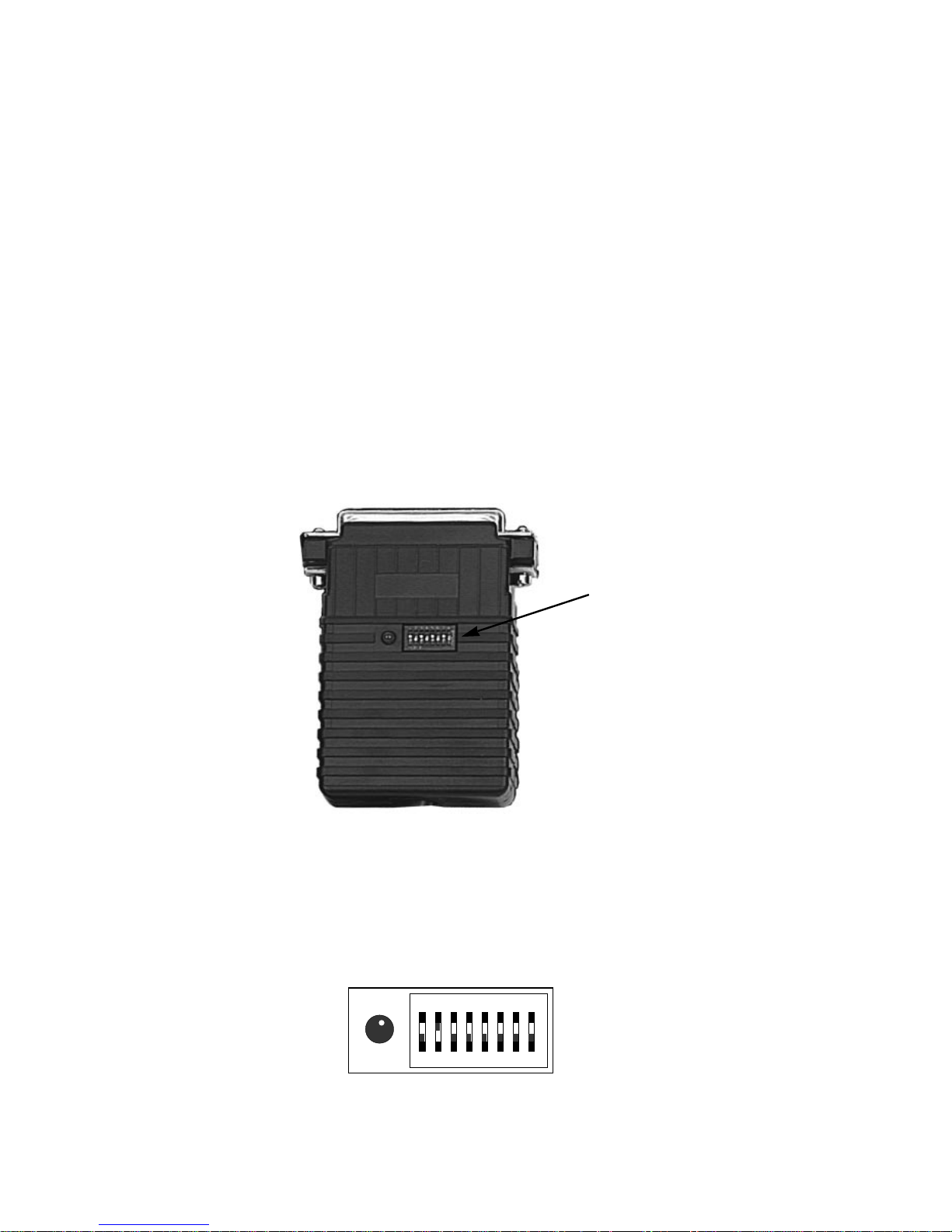
3.1 CONFIGURATION SWITCHES
The Model 2035 uses a set of eight external DIP switches (see
Figure 1, below) that allow configuration to a wide range of
applications. Because all eight switches are in one externally
accessible DIP switch package, there is no need to open the case for
configuration. The configuration switches allow you to select data
rates, parity, word length and flow control selection. The following
section describes all switch locations, positions and functions.
The Model 2035 uses a
miniature
configuration switch package.
To configure your unit, use a small screwdriver and gently push each
switch to its proper setting. The ON and OFF positions are shown in
Figure 2., below. Default settings for the DIP switches are shown in the
table on the following page. Detailed settings follow the table.
Figure 1. The location of the Model 2035 configuration switches
Figure 2. The miniature configuration switch package
OFF
12345678
DHS-8
Configuration
Switch
Page 6

Page 7

Switch 3 through 5: Data, Parity and Stop Bit
Switches 3 through 5 are used to specify the data, parity and stop
bits. The following table shows the settings that may be used:
Switches 6 through 8: Frequency and Data Rate
Switches 6 through 8 determine the frequency and data rate. The
following chart shows the settings that may be used.
6
1,200 OFF OFF ON
2,400 ON OFF ON
4,800 ON ON OFF
9,600 OFF ON ON
19,200 ON ON ON
38,400 OFF OFF OFF
57,600 ON OFF OFF
115,200 OFF ON OFF
Data Rate SW6 SW7 SW8
7B EP 1S ON ON ON
7B OP 1S OFF ON ON
7B NP 2S ON OFF ON
7B EP 2S OFF OFF ON
7B OP 2S ON ON OFF
8B EP 1S OFF ON OFF
8B OP 1S ON OFF OFF
8B NP 1S OFF OFF OFF
Stop
Data Parity Bit SW3 SW4 SW5
Page 8

Page 9

5.0 OPERATION
Once your interface converter is properly configured and installed,
it should operate transparently—as if it were a standard cable
connection. Operating power is derived from the RS-232 data and
control signals; there is no “ON/OFF” switch.
5.1 LED STATUS MONITORS
The Model 2035 features an easy-to-read status LED that glows
red to indicate the condition of the transmission line. Figure 1 shows
the location of the LED. The following chart describes the LED's
various functions.
The red LED indicator blinks to show data activity. However, since
there is only one indicator, it uses different LED codes to demonstrate
various messages. The following chart describes these codes:
LED Codes
● ● — ● ——— ● ● — ● ——— Computer is sending data
● ——— ● ——— ● ——— Serial device is connected; computer is
not sending data
● ● ——— ● ● ——— Both serial and parallel devices are
connected; computer not sending
data
● — ● ——— ● — ● ——— Printer not ready, data held in buffer
● ● ● ● ———● ● ● ● Computer ignoring flow control, data lost
Key:
● Blink
— Short pause
——— Long pause
Page 10

Page 11

APPENDIX B
PATTON MODEL 2035 INTERFACE CONNECTIONS
36 PIN CENTRONICS PARALLEL PORT CONNECTIONS
Pin Description Direction
1 Strobe Output
2 Data bit 0
3 Data bit 1
4 Data bit 2
5 Data bit 3
6 Data bit 4
7 Data bit 5
8 Data bit 6
9 Data bit 7
10 Acknowledge Input (active low)
11 Busy Input (active high)
12 Paper end
13 Select
18 +5 volts
32 Error
(16, 17, 19, 20, 21, 22, 23, 24,
25, 26, 27, 28, 29, 30, 33, 36)
Note: All other pins are unconnected
DB-25 SERIAL PORT CONNECTIONS
Pin Name Description
1 FG Connected to pin 7 with optional jumper
2 TXD Serial Transmit Data; also used as a
power source
3 RXD Serial Receive Data; also used as a power
source
4 RTS Request to Send; also used as a power source
5 CTS Clear to Send; also used as a power source
6 DSR Data Set Ready; also used as a power source
7 SG Signal Ground
8 DCD Carrier Detect; also used as a power source
9 +V in Used as a power source
20 DTR Data Terminal Ready; also used as a power
source
Note: All other pins are unconnected
}
I/O
}
Ground
Page 12

Page 13

Page 14

Page 15

Page 16

Dear Valued Customer,
Thank you for purchasing Patton Electronics products! We do
appreciate your business. I trust that you find this user manual helpful.
We manufacture one of the widest selections of data
communications products in the world including CSU/DSU's, network
termination units, powered and self-powered short range modems, fiber optic
modems, interface converters, baluns, electronic data switches, data-line surge
protectors, multiplexers, transceivers, hubs, print servers and much more. We
produce these products at our Gaithersburg, MD, USA, facility, and can
custom manufacture products for your unique needs.
We would like to hear from you. Please contact us in any of the
following ways to tell us how you like this product and how we can meet your
product needs today and in the future.
Web: http://www.patton.com
Sales E-mail: sales@patton.com
Support E-mail: support@patton.com
Phone - Sales (301) 975-1000
Phone - Support (301) 975-1007
Fax: (301) 869-9293
Mail: Patton Electronics Company
7622 Rickenbacker Drive
Gaithersburg, MD 20879 USA
We are committed to a quality product at a quality price. Patton
Electronics is ISO 9001 certified. We meet and exceed the highest
standards in the industry (CE, UL, etc.).
It is our business to serve you. If you are not satisfied with any
aspect of this product or the service provided from Patton Electronics or its
distributors, please let us know.
Thank you.
Burton A.Patton
Vice President
P.S. Please tell us where you purchased this product.
_______________________________________________________________
_______________________________________________________________
_______________________________________________________________
_______________________________________________________________
_______________________________________________________________
_______________________________________________________________
_______________________________________________________________
 Loading...