

Page 1
USER
MANUAL
SALES OFFICE
(301) 975-1000
TECHNICAL SUPPORT
(301) 975-1007
http://www.patton.com
Part #07M2026-D
Doc. #102031U
,
Rev. E
Revised 1/22/08
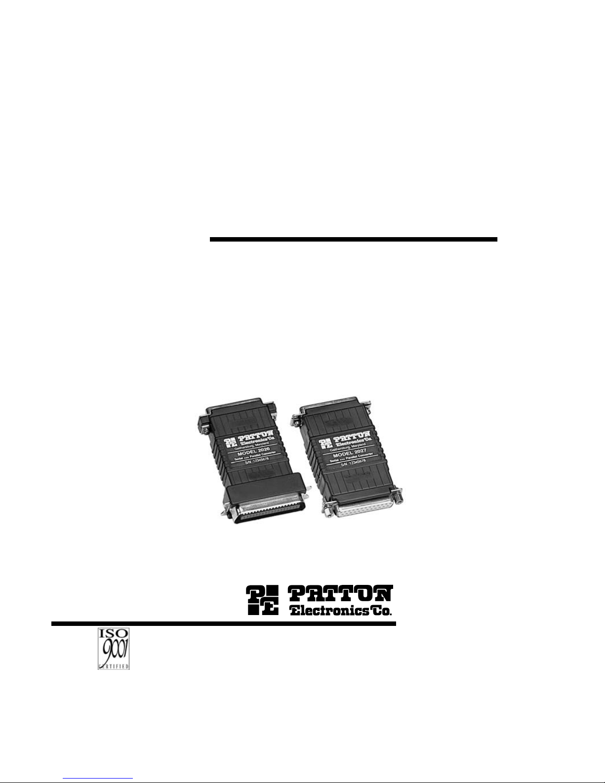
MODEL 2026 and
2027
Parallel to Serial/
Serial to Parallel
Interface Converters
An ISO-9001
Certified Company
Page 2

1.0 WARRANTY INFORMATION
Patton Electronics warrants all Model 2026 and Model 2027
components to be free from defects, and will—at our option—repair or
replace the products should they fail within one year from the first date
of shipment.
This warranty is limited to defects in workmanship or materials,
and does not cover customer damage, abuse or unauthorized
modification. If these products fail or do not perform as warranted, your
sole recourse shall be repair or replacement as described above.
Under no condition shall Patton Electronics be liable for any damages
incurred by the use of these products. These damages include, but are
not limited to, the following: lost profits, lost savings and incidental or
consequential damages arising from the use of or inability to use this
product. Patton Electronics specifically disclaims all other warranties,
expressed or implied, and the installation or use of this product shall be
deemed an acceptance of these terms by the user.
1.1 RADIO AND TV INTERFERENCE
The Model 2026 and Model 2027 generate and use radio
frequency energy, and if not installed and used properly—that is, in
strict accordance with the manufacturer's instructions—may cause
interference to radio and television reception. They have been tested
and found to comply with the limits for Class A computing devices in
accordance with the specifications in Subpart J of Part 15 of FCC rules,
which are designed to provide reasonable protection from such
interference in a commercial installation. However, there is no
guarantee that interference will not occur in a particular installation. If
they do cause interference to radio or television reception, which can
be determined by disconnecting the RS-232 interface, the user is
encouraged to try to correct the interference by one or more of the
following measures: moving the computing equipment away from the
receiver, re-orienting the receiving antenna and/or plugging the
receiving equipment into a different AC outlet (such that the computing
equipment and receiver are on different branches).
1.2 CE NOTICE
The CE symbol on your Patton Electronics equipment indicates
that it is in compliance with the Electromagnetic Compatibility (EMC)
directive and the Low Voltage Directive (LVD) of the Union European
(EU). A Certificate of Compliance is available by contacting Technical
Support.
1
Page 3

Page 4
2.0 GENERAL INFORMATION
Thank you for your purchase of this Patton Electronics product.
This product has been thoroughly inspected and tested and is
warranted for One Year parts and labor. If any questions or problems
arise during installation or use of this product, please do not hesitate to
contact Patton Electronics Technical Support at (301) 975-1007.
2.1 FEATURES
• Converts parallel data to serial data or vice versa
• Automatically selects parallel-to-serial or serial-to-parallel operation
• Automatically selects DCE/DTE modes
• Serial data rates to 38,400 bps
• No AC power required
• Supports both software and hardware flow control
• A five-state LED monitors status and diagnostics
• External configuration switches
• Ultra-miniature size
• Made in the USA
2.2 DESCRIPTION
The Patton Model 2026 and Model 2027 Parallel to Serial
Converters automatically convert RS-232 serial data to parallel data
format or vice versa. Incorporating advanced microprocessor
technology, they are able to automatically sense and select parallel and
serial modes, as well as DCE/DTE modes. Requiring no AC power, the
Model 2026 and 2027 support serial data rates to 38.4 Kbps.
For easy configuration, the Model 2026 and Model 2027 feature a
convenient set of external configuration switches. These accessible
configuration switches allow the user to control baud rate, parity, word
length and flow control. An easy-to-read LED indicator displays status
and operating condition.
Housed in an ultra-miniature ABS plastic case, the Model 2026
comes equipped with a DB-25 female or male connector on the serial
side and a Centronics 36 pin male connector on the parallel side. The
Model 2027 is housed in the same convenient case and comes
equipped with a DB-25 female connector on the serial side and male or
female connector on the parallel side.
3
Page 5

Page 6

The Model 2026 and Model 2027 use a miniature configuration
switch package. To configure your unit, use a small screwdriver and
gently push each switch to its proper setting. The ON and OFF
positions are shown in Figure 2. Default settings for the DIP switches
are shown in the table on the following page. Detailed settings follow
the table.
3.2 DETAILED SWITCH SETTINGS
This section provides detailed information about the function of
each DIP switch and lists all possible settings.
Switch 1:
Hardware/Software
Control
The setting for Switch 1 determines whether these interface
converters will control either hardware or software flow control.
Switch 2:
Enable/Disable LED Indicator
The setting for Switch 2 determines whether the LED indicator is
enabled or disabled.
5
Flow Control SW1
Hardware OFF
Software ON
LED SW2
Enabled ON
Disabled OFF
DIP SWITCH SUMMARY TABLE
Position Function Factory Default
SW1 Flow Control Off
SW2 LED Indicator On
SW3 Data, Parity, Stop Bits Off
SW4 Data, Parity, Stop Bits Off
SW5 Data, Parity, Stop Bits Off
SW6 Data Rate Off
SW7 Data Rate Off
SW8 Data Rate Off
Hardware
Enabled
8B, NP, 1S
9600 bps
}
}
Page 7

Page 8

Switch 3 through 5: Data, Parity and Stop Bit
Switches 3 through 5 are used to specify the data, parity and stop
bits. The following table shows the settings that may be used:
Switches 6 through 8: Frequency and Data Rate
Switches 6 through 8 determine the frequency and data rate. The
following chart shows the settings that may be used:
7
Figure 3. Installing the Model 2026 and 2027
Model 2026 or 2027
PC
Printer
Your cable
Page 9

Page 10

5.0 OPERATION
Once your interface converter is properly configured and installed,
it should operate transparently—as if it were a standard cable
connection. Operating power is derived from the RS-232 data and
control signals; there is no “ON/OFF” switch.
5.1 LED STATUS MONITORS
The Model 2026 and the Model 2027 feature easy-to-read status
LEDs that glow red to indicate the condition of the transmission line.
Figure 1 shows the location of these LEDs. The following chart
describes the LED’s various functions.
The red LED indicators blink to show data activity. However, since
there is only one indicator on each Model, it uses different LED codes
to demonstrate various messages. The following chart describes these
codes:
9
Page 11

Page 12

APPENDIX B
(continued)
SIGNAL DIRECTIONS
Converter
Function
Serial Port
Connected
Serial Data
Flow
Serial Software Flow
Ctrl. Signal
(XON/XOFF)
Serial Hardware
Flow Ctrl Signal
(DTR, CTS, DSR)
Serial to Parallel DTE TD
RD CTS, DSR
Serial to Parallel DCE RD
TD DTR
Parallel to Serial DTE RD
TD DTR
Parallel to Serial DCE TD
RD CTS, DSR
11
Page 13

Page 14

APPENDIX D
PATTON MODEL 2027 BLOCK DIAGRAM
Copyright ©
Patton Electronics Company
All Rights Reserved
13
Page 15

Page 16

 Loading...