

Page 1
MODEL 14TB
DB-25 to Terminal Block
Adapter
SALES OFFICE
(301) 975-1000
TECHNICAL SUPPORT
(301) 975-1007
http://www.patton.com
P/N 07M14TB-A
Doc# 070031UA
6/22/99
USER
MANUAL
Page 2
INSTALLATION
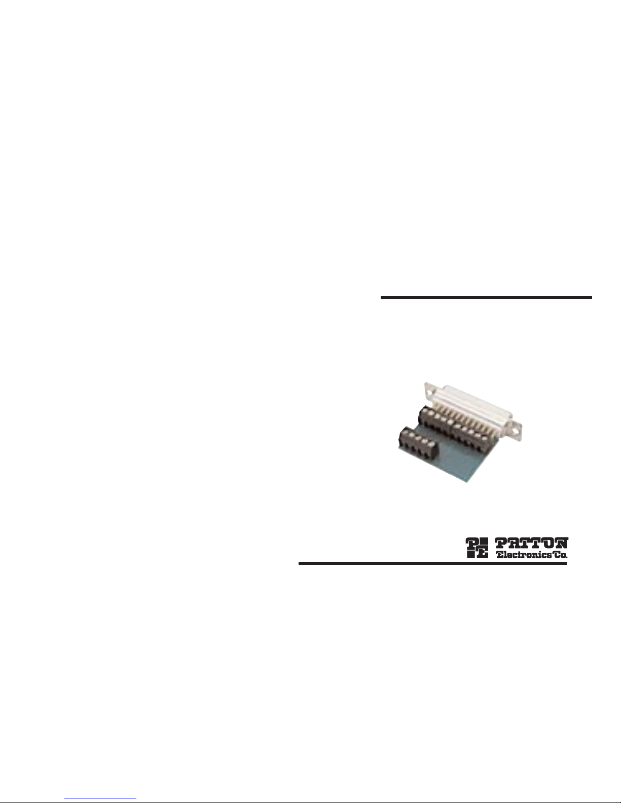
The Patton Model 14TB DB-25 to Ter minal Block Adapter lets you
terminate bare wires to a DB-25 connector (male or female versions
available). 15 screw-type terminals let you use the Model 14TB with
asynchronous or synchronous RS-232 devices. A strain relief collar
holds the cable firmly so that it resists pulling out. The Model 14TB
uses PCB construction for compactness and reliability. Follow these
steps for installation:
1. Remove the internal PC board assembly from the plastic case
(insert a small flat-head screw driver between the DB-25 connector and the lip of the case and twist to pop the case open).
2. Strip individual wires and inser t into ter minal slots according to the
RS-232 pinouts listed on the opposite page (note: the position of
the terminal blocks differs depending upon the DB-25 gender) .
Using a small flat-head screw driver, tighten each of the terminal
screws securely.
3. Position the two halves of the strain relief collar around the cable.
4. Position the two case halves so that the strain relief collar, DB-25
connector and captive screws/saddle washers are in the proper
location. Snap the two case halves together.
PINOUTS
PIN SIGNAL DESIGNATION
1 ............................Protective Ground (FGND)
2 ............................Transmit Data (TD)
3 ............................Receive Data (RD)
4 ............................Request to Send (RTS)
5 ............................Clear to Send (CTS)
6 ............................Data Set Ready (DSR)
7 ............................Signal Ground (SGND)
8 ............................Carrier Detect (DCD)
9 ............................+DC Test Voltage (Test)
15 ..........................DCE Transmit Clock (TCLK)
17 ..........................Receive Clock (RCLK)
18 ..........................Local Loopback (LL)
20 ..........................Data Terminal Ready (DTR)
21 ..........................Remote Loopback (RL)
25 ..........................Test Mode (TM)
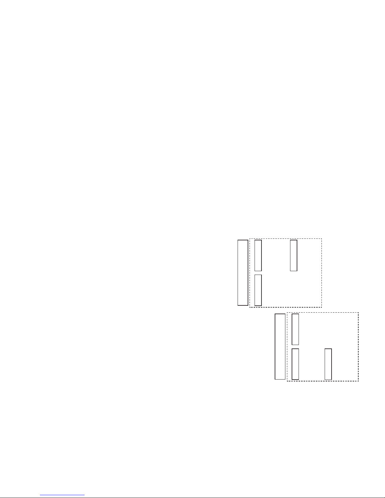
TERMINAL POSITIONS
DB-25
Male
(9) Test
(20) DTR
(15) TCLK
(8) DCD
(17) RCLK
(6) DSR
(25) TM
(18) LL
(21) RL
(1) FGND
(5) CTS
(4) RTS
(3) RD
(2) TD
(7) SGND
DB-25
Female
(7) SGND
(2) TD
(3) RD
(4) RTS
(5) CTS
(1) FGND
(21) RL
(18) LL
(25) TM
(6) DSR
(17) RCLK
(8) DCD
(15) TCLK
(20) DTR
(9) Test
 Loading...