

Page 1
USER
MANUAL
MODEL 1205RC
Synchronous V.35
Modem Eliminator:
Rack Mount Card
SALES OFFICE
(301) 975-1000
TECHNICAL SUPPORT
(301) 975-1007
http://www.patton.com
Part# 07M1205RC-C
Doc# 049041U,
Rev. D
Revised 1/22/08
An ISO-9001
Certified Company
Page 2

1.0 WARRANTY INFORMATION
Patton Electronics warrants all Model 1205RC components to be
free from defects, and will—at our option—repair or replace the product
should it fail within one year from the first date of shipment.
This warranty is limited to defects in workmanship or materials,
and does not cover customer damage, abuse or unauthorized modification. If this product fails or does not perform as warranted, your sole
recourse shall be repair or replacement as described above. Under no
condition shall Patton Electronics be liable for any damages incurred
by the use of this product. These damages include, but are not limited
to, the following: lost profits, lost savings and incidental or consequential damages arising from the use of or inability to use this product.
Patton Electronics specifically disclaims all other warranties,
expressed or implied, and the installation or use of this product shall be
deemed an acceptance of these terms by the user.
1.1 RADIO AND TV INTERFERENCE
The Model 1205RC generates and uses radio frequency energy,
and if not installed and used properly—that is, in strict accordance with
the manufacturer’s instructions—may cause interference to radio and
television reception. The Model 1205RC has been tested and found to
comply with the limits for a Class A computing device in accordance
with the specifications in Subpart J of Part 15 of FCC rules, which are
designed to provide reasonable protection from such interference in a
commercial installation. However, there is no guarantee that interference will not occur in a particular installation. If the Model 1205RC
does cause interference to radio or television reception, which can be
determined by turning the power off or removing the card, the user is
encouraged to try to correct the interference by one or more of the following measures: moving the computing equipment away from the
receiver, re-orienting the receiving antenna and/or plugging the receiving equipment into a different AC outlet (such that the computing equipment and receiver are on different branches).In the event the user
detects intermittent or continuous product malfunction due to nearby
high power transmitting radio frequency equipment, the user is strongly
advised to take the following steps: use only data cables with an external outer shield bonded to a metal or metalized connector; and, configure the rear card as shown in section 3.4 of this manual.
1.2 CE NOTICE
The CE symbol on your Patton Electronics equipment indicates
that it is in compliance with the Electromagnetic Compatibility (EMC)
directive and the Low Voltage Directive (LVD) of the Union European
(EU). A Certificate of Compliance is available by contacting Technical
Support.
1
Page 3

Page 4

2.0 GENERAL INFORMATION
Thank you for your purchase of this Patton Electronics product.
This product has been thoroughly inspected and tested and is warranted for One Year parts and labor. If any questions during installation or
use of the 1205RC, contact Patton Electronics Technical Support:
(301) 975-1007; http://www.patton.com; or, support@patton.com.
2.1 FEATURES
• V.35 (EIA-530) operation
• Synchronous data rates from 32 to 144 Kbps
• Host-to-host distances up to 300 feet
• Internal or external clocking
• All necessary data, clocking and control signals supported
• Constant or RTS controlled carrier selections
• RTS-CTS delay options of 0mS, 7mS or 53mS
• Front panel LEDs show TD, DTR and CD activity for each port
• Two UD-26 connectors on rear interface card
• Switchable 120V or 240V power supply
• Mounts in Patton’s 16-slot rack chassis and 2/4/8-slot Cluster
Boxes
• Made in the U.S.A.
2.2 DESCRIPTION
The Patton Model 1205RC synchronous modem eliminator
rack card lets two synchronous hosts communicate with each other in
the same room for a fraction of the cost of a pair of high speed
modems. Supporting synchronous data rates of 32, 48, 56, 64, 72,
112, 128 and 144 Kbps, the Model 1205RC can be configured to emulate dial-up or leased line service. Maximum distance between the
connected hosts is 300 feet. Timing can be set for internal or external
clock, and all necessary data, clocking and control signals are supported.
The Model 1205RC is designed to mount in Patton’s 2U high, 16-
slot rack chassis, as well as Patton’s 2/4/8-slot desktop Cluster Boxes.
This rack chassis and cluster boxes feature a switchable 120/240 VAC
power supply (optional 48 VDC) and hot swappable function/interface
cards mounted in a mid-plane architecture. Front panel LEDs show
TD, DTR and CD activity for both ports, as well as power. The rear
interface card has two UD-26 connectors for patching to the host
devices.
3
Page 5

Page 6
S1 through S3: Data Rate Setting
Switches S1 through S3 are set in combination to determine the
synchronous data rate for the Model 1205RC. Switch S4 is not active.
S1
S2 S3 S4 Setting
Off Off Off N/A 32 kbps
On Off Off N/A 48 kbps
Off On Off N/A 56 kbps
On On Off N/A 64 kbps
Off Off On N/A 72 kbps
On Off On N/A 112 kbps
Off On On N/A 128 kbps
On On On N/A 144 kbps
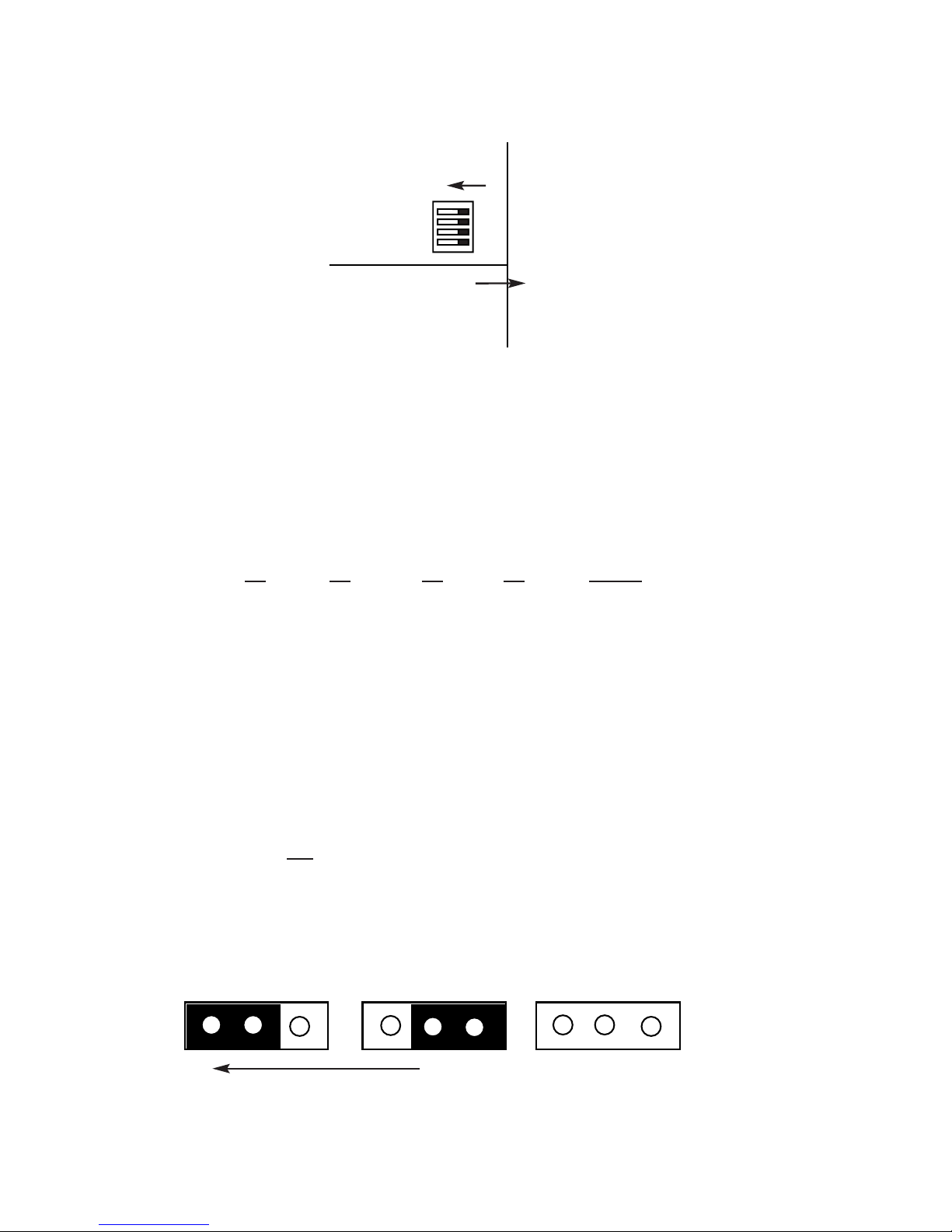
3.3 FUNCTION CARD JUMPERS
The Model 1205RC has two ports (Port A and Port B), and each
must be configured independently. Therefore, every function (such as
clocking) has two
jumpers associated with it. As Figure 3 (below)
shows, each jumper has three possible positions: strap covering posts
1 & 2, strap covering posts 2 & 3, or strap removed altogether. The
detailed description for each jumper presents all valid strap positions.
5
Figure 2. Model 1205RC DIP switch orientation on internal daughterboard.
On
4
3
2
1
Top of Card
Figure 3. Possible function card strap positions
123
Front of Card
123
123
Page 7

Page 8

JP2: Carrier Control (Port A)
The setting for jumper JP2 determines–with respect to Port A–
whether the Model 1205RC’s carrier is “constantly on” or “controlled
by RTS”.
JP2
Setting
Position 1&2 Carrier “Constantly ON” (factory default)
Position 2&3 Carrier “Controlled by RTS”
Strap Removed Not a valid setting
JP3: Carrier Control (Port B)
The setting for jumper JP3 determines–with respect to Port B–
whether the Model 1205RC’s carrier is “constantly on” or “controlled
by RTS”.
JP3
Setting
Position 1&2 Carrier “Controlled by RTS”
Position 2&3 Carrier “Constantly ON” (factory default)
Strap Removed Not a valid setting
JP5: Clock Source (Port A)
The setting for jumper JP5 determines–with respect to Port A–
whether clocking is internal or external. Note: Only
Port A may be set
for external clock.
JP5 (Port
A) Setting
Position 1&2 External Clock
Position 2&3 Internal Clock (factory default)
Strap Removed Not a valid setting
JP4: Clock Source (Port B)
The setting for jumper JP4 determines–with respect to Port B–
whether clocking is internal or receive loopback. Note
1
: If Port B is set
for receive loopback clock, Port A must
be set for external clock.
Note
2
: Port B may not be set for external clock.
JP4 (Port B)
Setting
Position 1&2 Receive Loopback Clock
Position 2&3 Internal Clock (factory default)
Strap Removed Not a valid setting
7
Page 9

Page 10

4.0 INSTALLATION
This section describes the functions of the Model 1000R16 rack
chassis, tells how to install front and rear Model 1205RC cards into the
chassis, and provides diagrams for wiring the interface connections
correctly.
4.1 THE MODEL 1000R16 RACK CHASSIS
The Model 1000R16 Rack Chassis (Figure 6) has sixteen card
slots, plus its own power supply. Measuring only 3.5” high, the Model
1000R16 is designed to occupy only 2U in a 19” rack. Sturdy front
handles allow the Model 1000R16 to be extracted and transported conveniently.
4.1.1 THE RACK POWER SUPPLY
The power supply included in the Model 1000R16 rack uses the
same mid-plane architecture as the modem cards. The front card of
the power supply slides in from the front, and the rear card slides in
from the rear. They plug into one another in the middle of the rack.
The front card is then secured by thumb screws and the rear card by
conventional metal screws.
9
Figure 6. Model 1000R16 Rack Chassis with power supply
WARNING! There are no user-serviceable parts in the
power supply section of the Model 1205RC. Voltage setting changes and fuse replacement should only be performed by qualified service personnel. Contact Patton
Electronics Technical support at (301)975-1007,
http://www.patton.com, or support@patton.com for more
information.
Page 11

Page 12

4.3 HOST (DTE) CONNECTION
The Model 1205RC rear card has two UD-26 connectors, labeled
“A1” and “B1” (see figure 7, below). These correspond to host (DTE)
connection Port A and Port B, as discussed in Section 3.0.
To connect V.35 host (DTE) devices A and B to the Model
1205RC, follow these instructions:
1. Configure the Model 1205RC for your specific application accord-
ing to the instructions in Section 3.0 of this manual.
2. Connect host devices A and B to the Model 1205RC using multi-
pair adapter cables (see Appendix B for a list of custom adapter
cables available from Patton Electronics). Observe the following
conditions when making connections :
a) Each multipair cable must not exceed 150 feet in length
(see Figure 8, below).
b) If external clock is used, the host (DTE) device supplying the
clock must
be connected to Port A. The Model 1205RC
cannot
receive an external clock on Port B (see Section 3.0
for configuration details).
c) If receive clock is used on Port B, Port A must
supply an
external clock (see Section 3.0 for configuration details).
11
Notice! Any terminal cable connected to the Model
1205RC must be shielded cable, and the outer shield must
be 360 degree bonded–at both ends–to a metal or metalized backshell.
Figure 7. Model 1205RC rear interface card, showing connectors
A1 B1
Page 13

Page 14

5.2 POWER-UP
There is no power switch on the Model 1205RC: Power is automatically applied to the 1205RC when its card-edge connector makes
contact with the chassis’ mid-plane socket, or when the chassis’ power
supply is turned on. Note: The 1205RC is a “hot swappable” card—it
will not be damaged by plugging it in or removing it while the rack is
powered up.
When the Model 1205RC is powered up, and both ports are passing data normally, the following LED conditions will exist:
• PWR = green
• TD = blinking red and green
• CD = green
• DTR = green
13
Page 15

Page 16

APPENDIX B
MODEL 1205RC FACTORY REPLACEMENT PARTS
The Patton Model 1205RC rack system features interchangeable
rear cards, power cords/fuses for international various operating environments and other user-replaceable parts. Model numbers, descriptions and prices for these parts are listed below:
Patton Model #
Description
1000RPEM..........................120/240V Rear Power Entry Module
1000RPSM-2.......................120/240V Front Power Supply Module
1000RPEM-DC ...................DC Rear Power Entry Module
1000RPSM-48A ..................48V Front Power Supply Module
1000RPEM-V ......................120/240V CE Compliant Rear Power
Entry Module
1000RPSM-V ......................120/240V CE Compliant Front Power
Supply Module
0805US ...............................American Power Cord
0805EUR.............................European Power Cord CEE 7
0805UK ...............................United Kingdom Power Cord
0805AUS.............................Australia/New Zealand Power Cord
0805DEN.............................Denmark Power Cord
0805FR ...............................France/Belgium Power Cord
0805IN.................................India Power Cord
0805IS.................................Israel Power Cord
0805JAP..............................Japan Power Cord
0805SW ..............................Switzerland Power Cord
0516FPB1 ...........................Single Width Blank Front Panel
0516FPB4 ...........................4-Wide Blank Front Panel
0516RPB1...........................Single Width Blank Rear Panel
0516RPB4...........................4-Wide Blank Rear Panel
056S1..................................Set of 16 #4 pan head screws/washers
1205-26M/35M....................cable, 6ft, UD-26 male to M/34 male
1205-26M/35F.....................cable, 6ft, UD-26 male to M/34 female
1205-26M/25M....................cable, 6ft, UD-26 male to DB-25 male
1205-26M/25F.....................cable, 6ft, UD-26 male to DB-25 female
15
Page 17

Page 18

Page 19

Page 20

 Loading...