

Page 1

Model 1195/8E1
Optical Multiplexer
Quick Start Guide
Part Number: 07M1195-QS, Rev. A
Revised: February 12, 2009
Sales Office: +1 (301) 975-1000
Technical Support: +1 (301) 975-1007
E-mail: support@patton.com
WWW: www.patton.com
Page 2

WARNING
• This device contains no user serviceable parts. The equipment shall be
returned to Patton Electronics for repairs, or repaired by qualified
service personnel.
• Mains Voltage: Line voltages are present when the power cord is connected. The mains outlet shall be within 10 feet (3 meters) of the
device, shall be easily accessible, and protected by a circuit breaker.
• For AC powered units, ensure that the power cable used meets all
applicable standards for the country in which it is to be installed, and
that it is connected to a wall outlet which has earth ground.
• Hazardous network voltages are present in WAN ports, regardless of
whether power to the unit is ON or OFF. To avoid electric shock, use
caution when near WAN ports. When detaching the cables, detach the
end away from the unit first.
• Do not work on the system or connect or disconnect cables during
periods of lightning activity.
• For units with an external power adapter, the adapter shall be a
listed Limited Power Source.
2
Model 1195/8E1 Quick Start Guide
Page 3
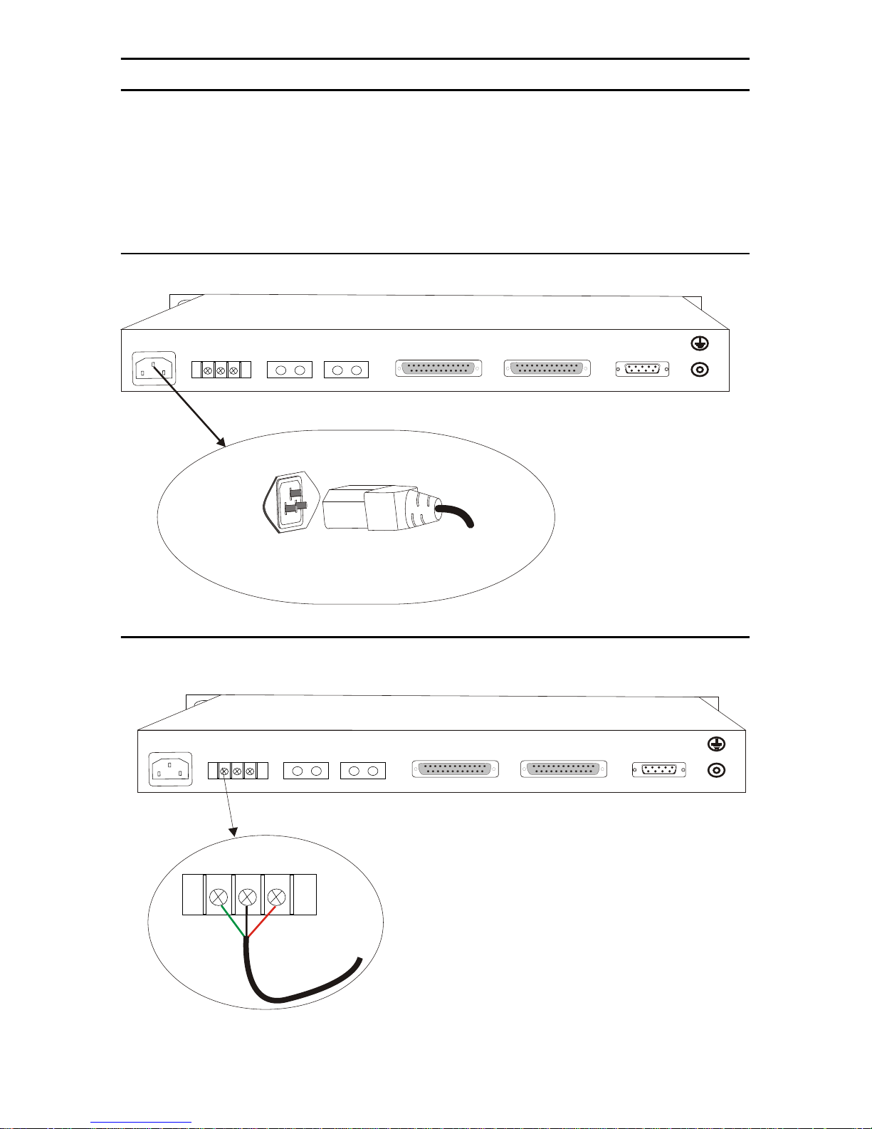
1.0 Connecting power
AC Mains version:
Please use the AC main cable (provided) to connect the system to your AC mains power
outlet.
DC Mains version
: Please connect the DC mains cable (provided) to the system. The polarity should not be
reversed while connecting. Otherwise, you can get your system damaged.
1.1 AC Power
To connect the AC 220V power:
DC 48 V
~ 220 V
PGND
GND
-48V
IEC 60320
Male on Unit
OPTICAL B
TX RX
OPTICAL A
TX RX
IEC 60320
Female
E1 8-5
II
From AC Source
(220V)
E1 4-1
II
CONSOLE
RS232
1.2 DC Power
To connect the DC -48V:
DC 48 V
~ 220 V
PGND
GND
DC Power
Cable
-48V
OPTICAL B
TX RX
OPTICAL A
TX RX
E1 8-5
II
E1 4-1
II
CONSOLE
RS232
Model 1195/8E1 Quick Start Guide
3
Page 4
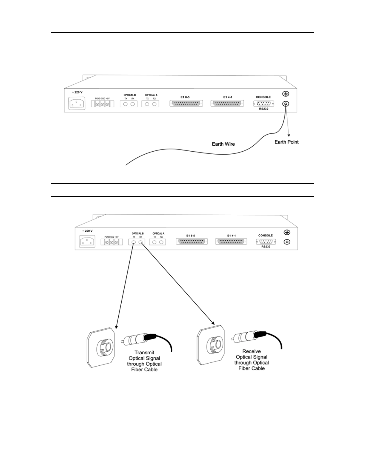
1.3 Grounding
When the equipment is used with the AC~220V power supply, the 3-core socket must be grounded for protection.The other equipment, e.g. optical terminal, connected with this equipment must also be grounded
To connect the Earth:
2.0 Connecting the optical interface
Note
Do not expose to the naked eye. Connect fiber cable to system when power is OFF.
Note
For Testing:
must be installed on the Optical Links. Otherwise, the optics will be permanently damaged.
4
ALWAYS INSTALL OPTICAL ATTENUATORS. For distances of less than 10 km, optical attenuators
Model 1195/8E1 Quick Start Guide
Page 5

DC 48 V
~ 220 V
3.0 Connecting the DB-37 connector
PGND
GND
-48V
OPTICAL B
TX RX
OPTICAL A
TX RX
E1 8-5
E1 4-1
CONSOLE
19
1
DB-37 (Female)
Connector
II
18
37
II
RS232
1
RJ-45 (F)
Connector
Model 1195/8E1 Quick Start Guide
2
RJ-45 (F)
Connector
4xE1 Signals
3
4
RJ-45 (F)
Connector
RJ-45 (F)
Connector
5
Page 6

4.0 Connecting E1 Links
Connect E1 line after ensuring that transmission device have been grounded. A Bit Error Rate (BER) test may be
conducted on E1 Link using a BERT tester to ensure that the E1 errors are within the permitted limits / threshold.
4.1 Definition for E1 Interfaces
The E1 Interface (RJ-45 connector) is defined as:
1 2 3 4 5 6 7 8
Rx+ Rx- N/C Tx+ Tx- N/C N/C N/C
Data In + Data In - Data Out + Data Out -
5.0 Connecting Ethernet Links
Please configure the Ethernet port of the equipment at both sides as well as the Ethernet Ports of the devices that
are connected to the equipment. Connect the Ethernet links.
Please ensure that the connecting LANs on both sides of the link are operating in the same IP domain.
5.1 Verifying the connection
Ping over the Ethernet connection from one side to the other (near-end to the far-end) to verify the link.
5.2 Definition for Ethernet Interfaces
The Ethernet Interface (RJ-45 connector) is defined as:
1 2 3 4 5 6 7 8
Tx+ Tx- Rx+ N/C N/C Rx- N/C N/C
Data Out + Data Out - Data In + Data In -
6
Model 1195/8E1 Quick Start Guide
Page 7

6.0 Connecting the RS-232 port
Note
An RS-232 COM port cable is provided with the 1195/8E1 system.
6.1 RS-232 port cable details
End 1
End 2
DB-9 (Female Connector)
DB-9 (Female Connector)
Type of cable Twisted pair cable - solid conductor
Number of pairs 2
Diameter 24 AWG
Length 3 meters
Connections As per details given below
Model 1195/8E1 Quick Start Guide
7
Page 8

6.2 RS-232 pin definition
DB-9 Pin Number Definition
2 RS-232 input signal for management
3 RS-232 output signal for management
5 GND
RS-232
Others NC
8
Model 1195/8E1 Quick Start Guide
Page 9

7.0 Configuring HyperTerminal
1.
Click on the Start button from the task bar on your PC.
2.
Select Programs > Accesories > Communications > HyperTerminal. The following screen will display:
3.
Enter a name for the new connection and click OK. The connection window will display:
4.
Select the COM port from the drop-down menu, and click OK. The properties window will display:
Model 1195/8E1 Quick Start Guide
9
Page 10

5.
Change the Bits per second option to 19200 and change the flow control option to None.
The COM Properties settings should be:
Bits per second
Data bits
Parity
Stop bits
Flow control
6.
Click Apply, then click OK.
7.
A new HyperTerminal session screen will display. Press Enter. The system prompt will appear on the
19200
8
None
1
None
screen. This prompt is generated by the system. Now, you may access/configure the system with the CLI
commands.
Note
Remember to save the settings for future use before you exit the HyperTerminal window.
Note
For detailed information about configuring the 1195/8E1 system using CLI commands or the Graphical User Interface (GUI), refer to the
Model 1195/8E1 Getting Started Guide
that came with your unit.
10
Model 1195/8E1 Quick Start Guide
Page 11

8.0 Additional Information
Refer to the
Model 1195/8E1 Getting Started Guide
located on the CD-ROM shipped with your device
.
For detailed information about:
•
Installing, configuring, operating, and troubleshooting
A.0 Customer and Technical Support
Toll-Free VoIP support: call
Online support: www
E-mail support:
support@patton.com
Telephone support:
Standard: +1 (301) 975-1007 (USA), Monday–Friday: 8:00 am to 5:00 pm EST (1300 to
•
2200 UTC/GMT)
Alternate: +41 (0)31 985 25 55 (Switzerland), Monday–Friday: 8:00 am to 5:00 pm CET (0900 to 1800
•
UTC/GMT)
Fax:
+1 (253) 663-5693
sip:support@patton.com
.patton.com
—answered within 1 business day
(USA)
or +41 (0)31 985 25 26 (
with a VoIP SIP client
Switzerland)
Model 1195/8E1 Quick Start Guide
11
Page 12

Copyright statement
Copyright © 2009, Patton Electronics Company. All rights reserved.
The information in this document is subject to change without notice. Patton Electronics assumes no
liability for errors that may appear in this document.
In accordance with the requirements of council directive 2002/96/EC on Waste of
Electrical and Electronic Equipment (WEEE), ensure that at end-of-life you separate
this product from other waste and scrap and deliver to the WEEE collection system in
your country for recycling.
12
Model 1195/8E1 Quick Start Guide
 Loading...