

Page 1

USER
MANUAL
MODEL 1180RC and
1184RC Single Fiber
Rack Card Modem
SALES OFFICE
(301) 975-1000
TECHNICAL SUPPORT
(301) 975-1007
http://www.patton.com
07M1180RC-D
Doc# 017031UD
Revised 03/11/99
CERTIFIED
An ISO-9001
Certified Company
Page 2

21
1.0 WARRANTY INFORMATION
Patton Electronics warrants all Model 1180RC/1184RC compo-
nents to be free from defects, and will—at our option—repair or replace
the product should it fail within one year from the first date of shipment.
This warranty is limited to defects in workmanship or materials,
and does not cover customer damage, abuse or unauthorized modification. If this product fails or does not perform as warranted, your sole
recourse shall be repair or replacement as described above. Under no
condition shall Patton Electronics be liable for any damages incurred
by the use of this product. These damages include, but are not limited
to, the following: lost profits, lost savings and incidental or consequential damages arising from the use of or inability to use this product.
Patton Electronics specifically disclaims all other warranties,
expressed or implied, and the installation or use of this product shall be
deemed an acceptance of these terms by the user.
1.1 RADIO AND TV INTERFERENCE
The Model 1180RC/1184RC generates and uses radio frequency
energy, and if not installed and used properly—that is, in strict accordance with the manufacturer’s instructions—may cause interference to
radio and television reception. The Model 1180RC/1184RC has been
tested and found to comply with the limits for a Class A computing
device in accordance with the specifications in Subpart J of Part 15 of
FCC rules, which are designed to provide reasonable protection from
such interference in a commercial installation. However, there is no
guarantee that interference will not occur in a particular installation. If
the Model 1180RC/1184RC does cause interference to radio or television reception, which can be determined by turning the power off, the
user is encouraged to try to correct the interference by one or more of
the following measures: moving the computing equipment away from
the receiver, re-orienting the receiving antenna and/or plugging the
receiving equipment into a different AC outlet (such that the computing
equipment and receiver are on different branches).
In the event that the user detects intermittent or continuous product malfunction due to nearby high power transmitting radio frequency
equipment, the user is strongly advised to take the following steps:
1) Use only data cables with an external outer shield bonded to a
metal or metalized connector.
2) Configure the rear card as shown in Section 3.2 in this manual.
1.2 CE NOTICE
The CE symbol on your Patton Electronics equipment indicates
that it is in compliance with the Electromagnetic Compatibility (EMC)
directive and the Low Voltage Directive (LVD) of the Union European
(EU). A Certificate of Compliance is available by contacting Technical
Support.
1.3 SERVICE
All warranty and non-warranty repairs must be returned freight prepaid and insured to Patton Electronics. All returns must have a Return
Materials Authorization number on the outside of the shipping container. This number may be obtained from Patton Electronics Technical
Service at (301) 975-1007, http://www.patton.com, or support@pat-
ton.com.
NOTE: Packages received without an RMA number will not be
accepted.
Patton Electronics’technical staff is also available to answer any
questions that might arise concerning the installation or use of your
Model 1180RC. Technical Service hours: 8AM to 5PM EST, Monday
through Friday.
Page 3

43
2.0 GENERAL INFORMATION
Thank you for your purchase of this Patton Electronics product.
This product has been thoroughly inspected by Patton’s qualified technicians. If any questions or problems arise during installation or use of
this product, please do not hesitate to contact Patton Electronics
Technical Support at (301) 975-1007.
2.1 FEATURES
• Synchronous or Asynchronous operation
• Communicates point-to-point over a single optical fiber
• Local and remote test modes
• Mounts in Patton’s Cluster Boxes and Rack System 1000R16P
• Data Rates:
Model 1180RC: aysnc; 0 to 38.4 Kbps
sync; 2.4, 9.6, 19.2, 38.4, 56, 64, 192 and 256 Kbps
Model 1184RC: aysnc; DC to 19.2 Kbps
sync; 4.8, 9.6, 14.4, 19.2, 28.8, 32.0, 56.0, 64.0, and 128 Kbps
• Distances to 2.5 Km (for Standard)
• Distances to 5 Km (for Double)
• Internal, external or receive loopback clocking
• Hardware and software flow control
• Ten front panel LEDs
• Available with ST or SMA connectors
2.2 DESCRIPTION
The Model 1180RC/1184RC Single Fiber Rack Card Modem
accomplishes point-to-point RS-232/V.35 communication over a
single
optical fiber. Mounting in Patton’s cluster box and 1000R16P rack system. the Model 1180RC supports synchronous data rates to 256 Kbps,
and asynchronous data rates to 38.4 Kbps, and the Model 1184RC
supports synchronous data rates to 128 kbps and asynchronous data
rates from DC to 19.2 kbps.The Model 1180RC/1184RC automatically
adapts to hardware or software flow control. Synchronous timing can
be set for internal, external or receive loopback clock.
The Model 1180RC/1184RC features extended data rate circuitry
that allows for single fiber distances between 2.5 and 5 Km. Optical
fiber may be connected to the Model 1180RC/1184RC using an ST or
SMA type interface.The Model 1180RC/1184RC encodes the electrical
signal using 3B4B modulation. The electrical signal is then converted
to an optical signal and transmitted using an 880 nm light emitting
diode, communicating over a single 62.5µ multi-mode fiber.
The Model 1180RC/1184RC features two test modes: local and
remote loopback. These loopback tests are activated via the serial
communication interface on the rear card. The local loopback test
monitors the RS-232/V.35 to modem connection. The remote loopback
test monitors the condition of the connection between the modems.
Page 4
65
3.0 CONFIGURATION
This section describes the location and orientation of the Model
1180RC/1184RC’s configuration switches and jumpers. Separate
descriptions are provided for the front “brains”card and the rear “interface” card.
3.1 FRONT CARD CONFIGURATION
The Model 1180RC/1184RC front card uses two sets of DIP
switches that allow configuration to a wide range of applications. DIP
switch set S1 has 4 switches and allows selection of data rates. DIP
switch set S2 has 8 switches and allows selection of clocking, handshake and test mode parameters.
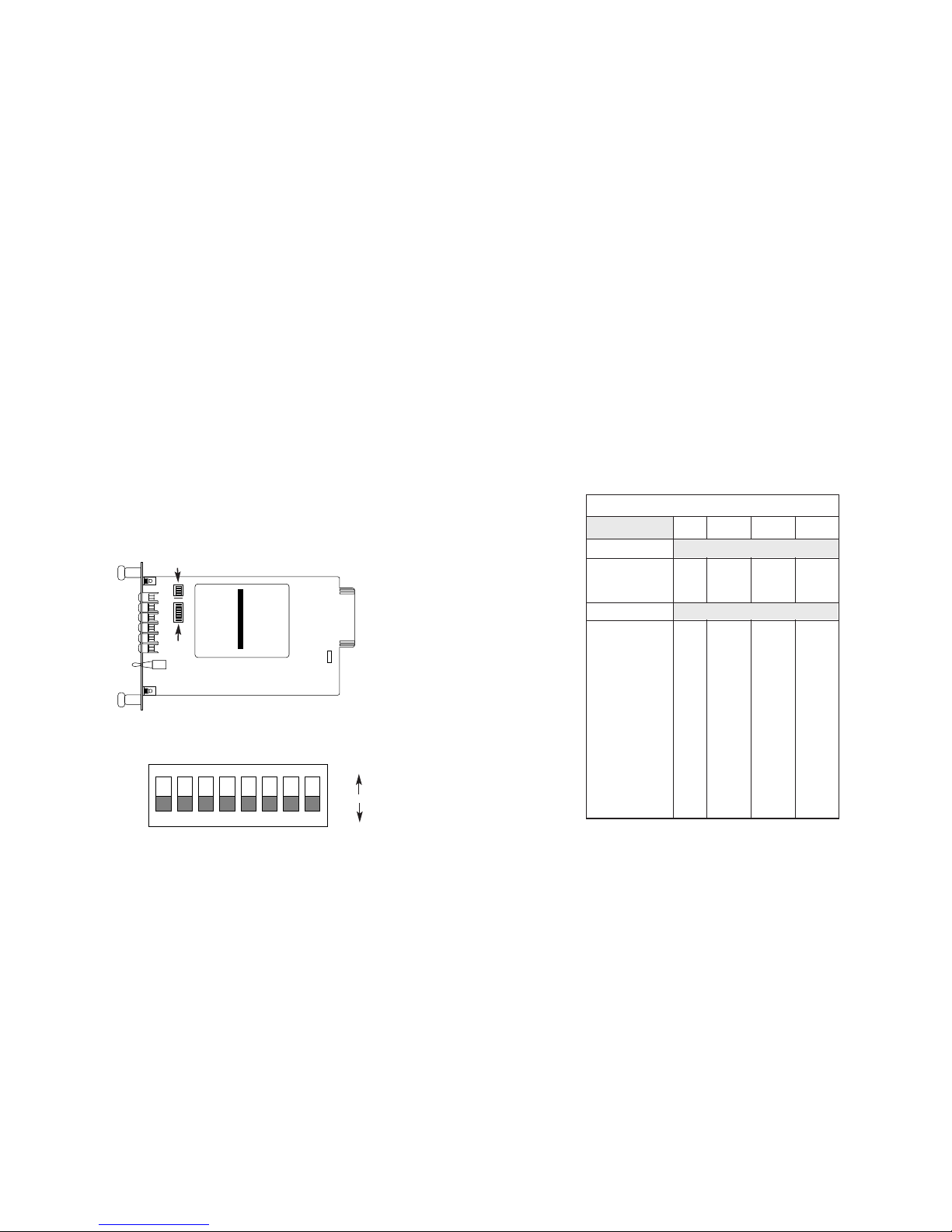
Figure 1 (below) shows the location of switch set S1 and S2 on
the 1180RC/1184RC front card. Figure 2 (below) shows the orientation
of DIP switch set S2 (S1 is identical).
3.1.1 SWITCH SET S1 OVERVIEW
DIP switch set S1 has 4 switches and is used to select the data
rate. Below are Table 1 (Model 1180RC) and Table 1A (Model 1184RC)
which shows each possible data rate and switch settings.
Important: When the data rate is followed by “dbl”, the space
between data packets is doubled. This means communication distances up to 5Km are possible. When the data rate is followed by “std”,
the space between data packets is standard. This means communication distances are limited to 2.5 Km.
Figure 1. Switch locations on the 1180RC/1184RC front card
S1
S2
ON
OFF
12345678
ON
Figure 2. Orientation of front card switch set S2
OFF
ON
1180RC DIP Switch Set S1
1234
Asynchronous
dc - 19.2k dbl. ON off off ON
dc - 38.4k std. ON off off off
Synchronous
2.4k std. ON ON ON off
9.6k std. off ON ON off
9.6k dbl. off ON ON ON
14.4k std. ON off ON off
19.2k dbl. ON off ON ON
38.4k dbl. off off ON ON
48k std ON ON off off
48k dbl. ON ON off ON
56k std. off ON off off
64k std. off off off off
64k dbl.* off* off* off* ON*
128k std. off off ON off
192k std. off ON off ON
256k std. ON ON ON ON
Table 1.Model 1180RC Switch Set SW1 Configurations, * Indicates Factory Default
Page 5

87
3.1.2 SWITCH SET S2 OVERVIEW
DIP switch set S2 has 8 switches and is used to specify clocking,
handshake and loopback modes. Table 2 (below) shows each setting
at a glance.
3.1.3 DETAILED SWITCH SETTINGS - S2
Whereas DIP switch set S1 is dedicated specifying data rates,
switch set S2 has multiple functions. Please refer back to Table 2,
above for an overview of all possible S2 configurations.
S2-1 & S2-2: Transmit Clock Selection
Switches 1 and 2 are used to specify the clocking method. The
Model 1180RC/1184RC can provide an internal clock, receive a clock
loopback, or receive an external clock. Internal clocking is the normal
(default) method.
S2-1 S2-2
On off = Internal Clock
(default setting)
off off = Received Loopback Clock
off On = External Clock
S2-3: Handshake Mode
The setting for switch 3 determines whether the Model
1180RC/1184RC operates in RTS/CTS (hardware) handshaking mode
or standard modem handshaking mode. In RTS/CTS mode, when one
unit drops RTS, CTS will drop on the other unit. In standard modem
mode, handshaking only functions on the local loops (between each
Model 1180RC/1184RC and its own DTE device).
S2-3
On = RTS/CTS
Off = Standard Modem
(default settings)
S2-4, S2-5 & S2-6: Not Used
S2-7 & S2-8: RS-232 Loopback Control
The Model 1180RC/1184RC gives you the option of enabling test
modes via the front panel toggle switch or via the RS-232/V.35 interface. Switch S2-7 controls the enabling of local analog loopback.
Switch S2-8 controls the enabling of remote loopback.
Local Analog Loopback
S2-7
off = Toggle Switch Control Only
(default settings)
On = RS-232/V.35 or Toggle Switch Control
1184RC DIP Switch Set S1
1234
Asynchronous
dc - 19.2k dbl. ON off off ON
Synchronous
4.8k dbl. off ON ON off
9.6k dbl. off ON ON ON
14.4k std. ON off ON off
19.2k dbl. ON off ON ON
28.8k std. off off ON off
32k dbl. off off off off
56k std. off ON off off
64k dbl.* off* off* off* ON*
128k dbl. ON ON ON ON
Table 1A.Model 1184RC Switch Set SW1 Configurations, * Indicates Factory Default
Table 2. Switch Set SW2 Configurations, * Indicates Factory Default
Dip Switch Set S2
12378
Transmit Clk Selection:
Internal Transmit Clock* ON* off*
Receive Loopback Clock off off
External Transmit Clock off ON
Handshake Mode:
RTS/CTS(default) ON
Standard Modem* off*
RS232/V.35 Loopback Control:
Local Analog Loopback
Toggle Switch Control Only* off*
RS232/V.35 & Toggle Ctr l ON
Remote Loopback
Toggle Switch Control Only* off*
RS232/V.35 & Toggle Ctr l ON
NOTE: Switches 4, 5 and 6 not used
Page 6

109
Remote Loopback
S2-8
off = Toggle Switch Control Only
(default settings)
On = RS-232/V.35 or Toggle Switch Control
3.1.4 REVERSIBLE “DAUGHTER BOARD”
The Model 1180RC/1184RC supports both RS-232 and V.35 electrical interfaces for the terminal connection port. Which electr ical interface is active is determined by the orientation of the small reversible
daughter board on the front card (see Figure 3, below). The daughter
board is clearly marked “This side up for RS-232” and “This side up
for V .35”. Note: When plugging the daughter board into the socket, the
arrow should always point toward the
front panel
of the PC board.
3.2 REAR CARD CONFIGURATION
The Model 1180RC/1184RC is compatible with four single-fiber
rear interface cards. Figure 4 (below) shows a rear view of each of
the cards.
Figure 5 (below) shows each of the possible interface port combinations and their part numbers.
FRONT THIS SIDE UP FOR RS-232
Figure 3. Terminal interface selection “daughter board”
ST/SMA
ST/SMA
Figure 4. Model 1180RC/1184RC interface card options
DB-25 F
M/34 F
RS-232/V.35 Fiber Optic Rear Card Part No.
DB-25 Female ST 1000RCM125ST
DB-25 Female SMA 1000RCM125SMA
V.35 Fiber Optic
M/34 Female ST 1000RCM134ST
M/34 Female SMA 1000RCM134SMA
Figure 5. Possible interface port combinations
Front
Panel
Page 7

1211
3.2.1 REAR CARD JUMPER SETTINGS
Figure 6 (below) shows jumper locations for the four rear card
options.These jumpers determine various grounding characteristics for
the RS-232/V.35.
Figure 7 (below) shows the orientation of the rear interface card
jumpers. The jumper can either be on pegs 1 & 2, or on pegs 2 & 3.
Table 3 (below) provides an overview of interface jumper functions
for the rear interface cards. Following this overview is a detailed
description of each jumper’s function.
DTE Shield & Frame Ground (JB3)
In the connected position, this jumper links DB-25 pin 1 (M/34 pin
A) & frame ground. In the open position, pin 1(pin A) is “lifted” from
frame ground.
JB3
Position 1&2 = DTE Shield (DB-25 Pin 1 or M/34 Pin A)
and FRGND Connected
Position 2&3 = DTE Shield (DB-25 Pin 1 or M/34 Pin A)
and FRGND Not Connected
Signal Ground & Frame Ground (JB4)
In the connected position, this jumper links DB-25 pin 7 or M/34
pin B (Signal Ground) and frame ground. In the open position, pin 1
(or pin B) is “lifted” from frame ground.
JB4
Position 1&2 = SGND (DB-25 pin 7 or M/34 pin B)
and FRGND Connected
Position 2&3 = SGND (DB-25 pin 7 or M/34 pin B)
and FRGND Not Connected
Figure 6. Rear card jumper locations
JB4
JB3
Figure 7. Orientation of interface card straps
123 123 123
REAR CARD STRAP SUMMARY
Strap Function Position 1&2 Position 2&3
JB3 DTE Shield (Pin1) & FRGND Connected Open*
JB4 FRGND & SGND Connected Open*
Table 3. Summary of Strap Settings, * Indicates Factory Default
1 2 3
3
2
1
Page 8

1413
4.0 INSTALLATION
This section describes the functions of the Model 1000R16P rack
chassis, tells how to install front and rear Model 1180RC/1184RC
cards into the chassis, and provides instructions for connecting the
interface cables.
4.1 THE MODEL 1000R16 RACK CHASSIS
The 1000R16 Rack Chassis (Figure 8, below) has sixteen short
range modem card slots, plus its own power supply. Measuring only
3.5” high, the 1000R16 is designed to occupy only 2U in a 19” rack.
Sturdy front handles allow the 1000R16 to be extracted and transported conveniently.
4.1.1 THE RACK POWER SUPPLY
The power supply included in the Model 1000R16 rack uses the
same mid-plane architecture as the modem cards. The front card of
the power supply slides in from the front, and the rear card slides in
from the rear. They plug into one another in the middle of the rack.
The front card is then secured by thumb screws and the rear card by
conventional metal screws.
Switching the Power Supply On and Off
The power supply on/off switch is located on the front panel.
When plugged in and switched on, a red front panel LED will glow.
Since the Model 1000R16P is a “hot swappable”rack,
it is not neces-
sary for any cards to be installed before switching on the power supply
.
The power supply may be switched off at any time without harming the
installed cards.
4.2 INSTALLING THE MODEL 1180RC/1184RC INTO THE CHASSIS
The Model 1180RC/1184RC is comprised of a front card and a
rear card. The two cards meet inside the rack chassis and plug into
each other via mating 50 pin card edge connectors. Use the following
steps as a guideline for installing each Model 1180RC/1184RC into the
Model 1000R16P rack chassis:
1. Slide the rear card into the back of the chassis along the metal
rails.
2. Secure the rear card using the metal screws provided.
3. Slide the front card into the front of the chassis. It should meet the
rear card when it’s almost all the way into the chassis.
4. Push the front card
gently
into the card-edge receptacle of the
rear card. It should “click” into place.
5. Secure the front card using the thumb screws.
NOTE: Since the Model 1000R16P chassis allows “hot swapping”
of cards, it is
not necessary to power down
the rack when you
install or remove a Model 1180RC/1184RC.
4.3 WIRING THE MODEL 1180RC/1184RC
Each of the rear interface cards compatible with the Model
1180RC/1184RC has one terminal interface port (DB-25 or M/34) and
a single multimode fiber port (ST or SMA). This section describes connection procedures for the terminal cable and fiber cable.
Figure 8. Model 1000R16 rack chassis with power supply
WARNING! There are no user-serviceable parts in the
power supply section of the Model 1180RC/1184RC.
Voltage setting changes and fuse replacement should
only be performed by qualified service personnel.
Contact Patton Electronics Technical support at (301)9751007 for more information.
Page 9

1615
4.3.1 TERMINAL INTERFACE CONNECTION
The Model 1180RC/1184RC is wired as a DCE, and allows for
three possible terminal interface connections:
• RS-232C/V.24 (electrical) + DB-25 female (physical)
• V.35 (electrical) + DB-25 female (physical)
• V.35 (electrical) + M/34 female (physical)
To select the appropr iate
electrical
interface, please refer to
Section 3.1.4 of this manual. To select or construct a cable with the
appropriate
physical
interface pin-outs, please refer to the diagrams in
Appendix B and Appendix C of this manual.
4.3.2 FIBER CONNECTIONS
The Model 1180RC/1184RC is designed to work with the standalone Model 1180, or with another Model 1180RC/1184RC. In either
case, you will need one unit at each end of a
single
fiber cable. This
cable connects to the Model 1180RC/1184RC using either an ST or an
SMA connector. Figure 9 (below) shows a close-up of each of these
connector types.
The cable must be multi-mode 50 or 62.5µ, for
optimal performance, use 62.5µ.
5.0 OPERATION
Once you have configured each Model 1180RC/1184RC and connected the cables, you are ready to operate the units. This section
describes the LED status monitors, the power-up procedure, and the
use of the built-in test modes.
5.1 LED STATUS MONITORS
The Model 1180RC/1184RC features eleven front panel status
LEDs that indicate the condition of the modem and communication link.
Figure 10 shows the front panel location of each LED. Following
Figure 10 is a description of each LED’s function.
• The green “PWR” LED glows when power is applied to the modem
card through its mid-plane chassis connection.
• The green “TD” and “RD” indicators blink to show positive state
data activity. The Red “TD” and “RD” indicators blink to show negative state data activity. Solid red indicates an idle state.
• The green “RTS”and “CD” indicators glow solid to show the con-
trol signal is on. The red “RTS” and “CD” indicators glow solid to
show the control signal is off. When the 1180RC/1184RC is connected to a DTE, RTS will glow green. CD will glow green for an
incoming signal from the line.
• The green “Test” LED glows when either test mode is activated.
Figure 9. Close-up of ST and SMA connections
ST
SMA
alignment pin
faces down
Figure 10. Model 1180RC/1184RC Front Panel, Showing LEDs and Switch
Model 1180RC
Power
TD
RD
RTS
AnalogRemote
Test
Page 10

1817
5.2 POWER-UP
There is no power switch on the Model 1180RC/1184RC: Power is
automatically applied to the 1180RC/1184RC when its card-edge connector makes contact with the chassis’ mid-plane socket, or when the
chassis’ power supply is turned on.
Note:The 1180RC/1184RC is a
“hot swappable”card—it will not be damaged by plugging it in or
removing it while the rack is powered up.
When the local and remote
Model 1180RCs/1184RCs are
both
powered up, and are passing data
normally
, the following LED conditions will exist:
• PWR = green
• TD & RD = flashing red and green
• RTS & DCD = green
• TEST = off
5.3 LOOPBACK TEST MODES
The Model 1180RC/1184RC offers two loopback test modes to
evaluate the condition of the modems and the communication link (see
Figure 11, below). Both tests can be activated physically from the front
panel, or via the RS-232/V.35 interface.
5.3.1 ANALOG LOOPBACK
The Analog Loopback test checks the operation of the local Model
1180RC/1184RC, and is
performed separately on each unit.
Any data
sent to the local Model 1180RC/1184RC in this test mode will be
echoed (returned) back to the user device. For example, characters
typed on the keyboard of a terminal will appear on the terminal screen.
To perform an analog loopback test, follow these steps:
1. Activate Analog Loopback. This may be done in one of two
ways:(1) by moving the front panel toggle switch RIGHT to
“Analog”, (2) by raising the LAL signal pin on the RS-232/V.35
interface. Note: Make sure switch SW1-7 is enabled. Once
Analog Loopback is activated, the Model 1180RC/1184RC
transmit output is connected to its own receiver. The “TEST”
LED should be lit.
2. Verify that the data terminal equipment is operating properly
and can be used for a test.
3. Perform a BER (bit error rate) test on the system, using external test equipment.
4. Perform a BER test on each unit. If the BERT test equipment
indicates no faults, and the data terminal indicates a fault, follow the manufacturer’s checkout procedures for the data terminal. Also, check the RS-232/V.35 interface cable between
the terminal and the Model 1180RC/1184RC.
5.3.2 REMOTE LOOPBACK
The Remote Loopback test checks the performance of both the
local and remote Model 1180RCs/1184RCs,
and
the communication
link between them. Any characters sent to the remote Model
1180RC/1184RC in this test mode will be returned back to the originating device. For example, characters typed on the keyboard of the local
terminal will appear on the local terminal screen
after
having been
passed to the remote Model 1180RC/1184RC/1184RC and looped
back. To perform an RDL test, follow these steps:
1. Activate Remote Loopback. This may be done in two ways:
(1) by moving the front panel toggle switch LEFT to “Remote”,
(2) by raising the RDL signal pin on the RS-232/V.35 interface. Note: be sure that DIP switch SW1-8 is enabled.
2. Verify that the DTE equipment on the local end is operating
properly and can be used for a test.
3. Perform a BER test on the system, using external test equipment.
4. If the remote BER test indicates that errors
are
present, and
the local analog loopback/BER tests showed that both Model
1180RCs/1184RCs were functioning properly, this suggests a
problem with the FIBER between the two modems. If you still
have errors, call Patton Technical Support at (301) 975-1007.
RD
TD
TD
RD
Local 1180RC/1184RC
In Normal Mode
Remote 1180RC/1184RC
In Normal Mode
TX
RX
TX
RX
TX
RX
TX
RX
RD
TD
TD
RD
Local 1180RC/1184RC
In Analog Looback
Remote 1180RC/1184RC
In Normal Mode
TX
RX
TX
RX
RD
TD
TD
RD
Local 1180RC/1184RC
Remote Looback
Remote
1180RC/1184RC
In Normal Mode
Figure 11. Local and Remote Loopback Test Modes
Page 11

2019
APPENDIX A
TROUBLESHOOTING
SYMPTOM PROBLEM SOLUTION
Carrier Detect (CD) If CD is red, possible Check for ongoing
LED is
red
synchronization loss power loss or break in
fiber if CD does not go
green within 60 sec-
onds.
OR
Carrier Detect (CD) Test Mode switch is Make sure the Test
LED is
green
,but in the wrong position Mode switch is set to
1180RCs/1184RCs NORMAL on both
are not communi- Model 1180RC/1184RC
cating.
DIP switches are set Check all DIP switch
improperly settings, esp.Data
Rate, against Section
3; make sure both
Model 1180RC/1184RC
are configured the
same way
Fiber link is con- Check the ST or SMA
nected improperly connection on the back
of both Model
1180RC/1184RC
RS-232/V.35 connec- Check RS-232/V.35
tions are faulty or cable continuity and
cables are pinned pinning
wrong
Data passed, but Incorrect DIP switch Switch 7 must be in the
hardware flow con- setting ON condition for hard-
trol doesn’t work ware flow control sig-
nals to pass between
Models 1180RCs or
1184RCs; both units
must be set the same
way
APPENDIX A
TROUBLESHOOTING
(continued)
SYMPT
OM PROBLEM SOLUTION
Model 1180RCs Incorrect DIP switch Switch 8 (internal/exter-
and 1184RCs setting nal clock) must be set
work in async. the same way for both
mode, but not Model 1180RC/1184RC
sync. mode
Page 12

2221
APPENDIX B
V.35 INTERFACE STANDARDS (DCE)
APPENDIX C
RS-232 INTERFACE STANDARDS (DCE)
1 - (FG) Frame Ground Common
2 - Transmit Data A To 1180RC/1184RC
3 - Receive Data A From 1180RC/1184RC
4 - (RTS) Request to Send To 1180RC/1184RC
5 - (CTS) Clear to Send From 1180RC/1184RC
6 - (DSR) Data Set Ready From 1180RC/1184RC
7 - (SG) Signal Ground Common
8 - (CD) Carrier Detect From 1180RC/1184RC
9 - Receive Clock B From 1180RC/1184RC
11 - External Clock B To 1180RC/1184RC
12 - Transmit Clock B From 1180RC/1184RC
To 1180RC/1184RC Data Ter m. Ready (DTR) - 20
DIRECTION CCITT V.35/EIA-530 INTERFACE (DB-25 Male) DIRECTION
To 1180RC/1184RC External Clock A - 24
From1180RC/1184RC Transmit Clock A - 15
From 1180RC/1184RC Receive Clock A - 17
To 1180RC/1184RC Local Analog Loop (LAL) - 18
To 1180RC/1184RC
Remote Digital Loop
(RDL) - 21
From 1180RC/1184RC Test Mode - 25
To 1180RC/1184RC Transmit Data B - 14
From 1180RC/1184RC Receive Data B - 16
B
F
L
R
V
Z
DD
NN
A
E
K
U
Y
CC
HH
MM
D
J
N
T
X
BB
FF
LL
H
M
S
W
AA
EE
KK
A
JJ
P
Frame Ground -A
Request to Send -C
Data Set Ready -E
Data Ter minal Ready -H
(Not Used) -K
(Not Used) -M
Transmitted Data (A) -P
Transmitted Data (B) -S
External Clock (A) -U
External Clock (B) -W
Transmit Clock (A) -Y
Transmit Clock (B) -AA
B- Signal Ground
D- Clear To Send
F- Data Carrier Detect
L- Remote Digital Loop
N- Local Analog Loop
R- Receive Data (A)
T- Receive Data (B)
V- Receive Clock (A)
X- Receive Clock (B)
CCITT V.35 Interface (M/34 Female)
1- (FG) Frame Ground
2- (TD) Transmit Data To 1180RC/1184RC
3- (RD) Receive Data From 1180RC/1184RC
4- (RTS) Request to Send To 1180RC/1184RC
5- (CTS) Clear to Send From 1180RC/1184RC
6- (DSR) Data Set Ready From 1180RC/1184RC
7- (SG) Signal Ground
8- (DCD) Data Carrier Detect From 1180RC/1184RC
To 1180RC/1184RC Data Ter m. Ready (DTR) - 20
DIRECTION STANDARD “DCE”SETTING (DB-25 Male) DIRECTION
To 1180RC/1184RC Exter nal Clock - 24
From 1180RC1184RC Transmit Clock - 15
From 1180RC/1184RC Receive Clock - 17
Page 13

23 24
APPENDIX D
SPECIFICATIONS
Transmission Format: Asynchronous or synchronous
Range: 2.5 Km at all data rates, 5 Km at
specified data rates
Data Rates: Model 1180RC: aysnc; 0 to 38.4 Kbps
sync; 2.4, 9.6, 19.2, 38.4, 56, 64, 192
and 256 Kbps
Model 1184RC: aysnc; DC to 19.2 Kbps
sync; 4.8, 9.6, 14.4, 19.2, 28.8, 32.0,
56.0, 64.0, and 128 Kbps
Interface: EIA RS-232/V.35 / CCITT V.35
Transmit Mode: Single 62.5 or 50 µ core, multi-mode
fiber cable, Optimal performance is with
62.5 µ cable
Clocking: Internal, external or Receive Recovered
clock
Handshaking: Software (X-ON/X-OFF) or hardware
(RTS/CTS), both modes available at all
times
Application: Point-to-point
Typical Link Budget: 8 dB with 50 µ cable; 12 dB with 62.5 µ
cable
Responsivity Minimum: 0.12 A/w
LED Indicators: TD, RD, RTS, CD, Power, Test
Diagnostics: Local and remote loopback
Connectors: DB-25 female (RS-232/V.35), ST or
SMA (fiber), M/34 female (V.35)
Dimensions: 4.127” W x 1.52 H x 5.0” L
APPENDIX E
PATTON ELECTRONICS MODEL 1180RC/1184RC
FACTORY REPLACEMENT PART NUMBERS
FRONT AND REAR CARDS
PART NUMBER DESCRIPTION
1180RC/35/SMA ......................Single-Fiber SRM Rack Card
(M34F/SMA Fiber)
1180RC/35/ST..........................Single-Fiber SRM Rack Card
(M34F/ST Fiber)
1180RC/SMA............................ Single-Fiber SRM Rack Card
(DB25F/SMA Fiber)
1180RC/ST ..............................Single-Fiber SRM Rack Card
(DB25F/ST Fiber)
1184RC/35/SMA ......................Single-Fiber SRM Rack Card
(M34F/SMA Fiber)
1184RC/35/ST..........................Single-Fiber SRM Rack Card
(M34F/ST Fiber)
1184RC/SMA............................ Single-Fiber SRM Rack Card
(DB25F/SMA Fiber)
1184RC/ST ..............................Single-Fiber SRM Rack Card
(DB25F/ST Fiber)
1000RCM125ST ......................Rear Card (DB25F/ST)
1000RCM125SMA.................... Rear Card (DB25F/SMA)
1000RCM134ST ......................Rear Card (M34F/ST)
1000RCM134SMA.................... Rear Card (M34F/SMA)
 Loading...