

Page 1
USER
MANUAL
MODEL 1140ARC
RS-232 Fiber Optic
Rack Card Modem
w/ V.54 & V.52 Diagnostics
SALES OFFICE
(301) 975-1000
TECHNICAL SUPPORT
(301) 975-1007
http://www.patton.com
Part #07M1140ARC-A
Doc #018032U
,
Rev. B
Revised 1/22/08
CERTIFIED
An ISO-9001
Certified Company
Page 2

Page 3

1.3 SERVICE
All warranty and nonwarranty repairs must be returned freight
prepaid and insured to Patton Electronics. All returns must have a
Return Materials Authorization number on the outside of the shipping
container. This number may be obtained from Patton Electronics
Technical Support: (301) 975-1007; http://www.patton.com; or,
support@patton.com.
NOTE: Packages received without an RMA number will not be
accepted.
Patton Electronics' technical staff is also available to answer any
questions that might arise concerning the installation or use of your
Model 1140ARC. Technical Service hours: 8AM to 5PM EST, Monday
through Friday.
2
Page 4

Page 5
3.0 CONFIGURATION
This section describes the location and orientation of the Model
1140ARC’s configuration switches and jumpers, and provides detailed
instructions for all possible settings.
The Model 1140ARC uses a combination of DIP switches and
jumpers that allow configuration to an extremely wide range of
applications. Designed around a mid-plane architecture, the Model
1140ARC incorporates both front and rear cards. Configuration of both
may be necessary. The switches/jumpers are accessible when the
cards are removed from the rack chassis. Once configured, the Model
1140ARC is designed to operate transparently, without need for
frequent re-configuration.
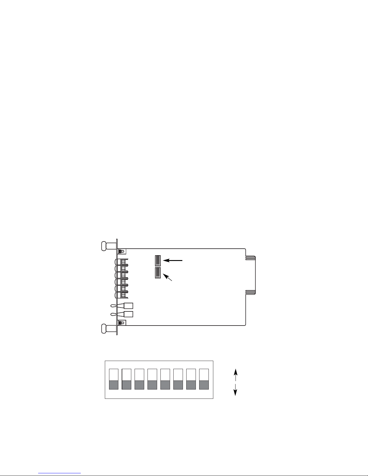
3.1 FRONT CARD CONFIGURATION
The Model 1140ARC front card has two sets of eight switches (S1 &
S2), which are mounted on the PC board (Figure 1, below). These
configuration switches allow you to configure the Model 1140ARC for a
wide range of applications. The ON/OFF orientation of the DIP
switches is shown in figure 2 (below).
4
Figure 1. Model 1140ARC front card jumper locations
Figure 2. Close-up of DIP switches showing “ON” and “OFF” positions
12345678
ON
OFF
ON
Switch Set 1
(Switch 1:1 on bottom)
SwitchSet 2
(Switch 2:1 on bottom)
Page 6

Page 7

S1-5 and S1-6: Clock Source
Switches S1-5 and S1-6 are set in combination to determine the
transmit clock source for the Model 1140ARC.
S1-5
S1-6 Setting
On On Internal transmit clock
Off On Receive recover clock
On Off External transmit clock
S1-7: Asynchronous/Synchronous Mode
The setting for switch S1-7 determines whether the Model
1140ARC is in asynchronous or synchronous operating mode.
S1-7
Setting
On Asynchronous
Off Synchronous
S1-8: Carrier Control Method
The setting for switch S1-8 determines whether the carrier is
“constantly on” or “controlled by R
TS”. This setting allows for operation
in switched carrier, multipoint and/or hardware handshaking
applications.
S1-8
Setting
Off Constantly On
On Switched Carrier
6
Page 8

Page 9

S2-4 and S2-5: RTS/CTS Delay
The combined settings for switches S2-4 and S2-5 determine the
amount of delay between the time the Model 1140ARC “sees” RTS and
when it sends CTS. Options are no delay, 7 ms and 53 ms.
S2-4
S2-5 Setting
On On 7 mS
Off On 53 mS
On Off No delay
Off Off No delay
S2-8: V.54 Loopback Test Enable
To reset the V.54 circuit, set switch S2-6 to the “ON” position, then
back to the “OFF” position..
S2-8
Setting
Off V.54 Enable
On V.54 Disable
3.2 REAR CARD CONFIGURATION
The Model 1140ARC is compatible with two dual-fiber interface
cards, one with dual ST connectors and one with dual SMA connectors.
Both cards use an HD-26 female for the RS-232 interface. The single
configuration jumper (JB1) functions identically on both cards. Figure 3
(below) shows the jumper’s location.
8
Figure 3. Model 1140ARC rear card jumper location
JB1
(pin 1 on right)
3 2 1
Page 10

Page 11

10
4.0 INSTALLATION
This section describes the functions of the Model 1000R16 rack
chassis, tells how to install front and rear Model 1140ARC cards into
the chassis, and provides instructions for connecting the interface
cables.
4.1 THE MODEL 1000R16 RACK CHASSIS
The 1000R16 Rack Chassis (Figure 5, below) has sixteen short
range modem card slots, plus its own power supply. Measuring only
3.5” high, the 1000R16 is designed to occupy only 2U in a 19” rack.
Sturdy front handles allow the 1000R16 to be extracted and transported
conveniently.
4.1.1 THE RACK POWER SUPPLY
The power supply included in the Model 1000R16 rack uses the
same mid-plane architecture as the modem cards. The front card of
the power supply slides in from the front, and the rear card slides in
from the rear. They plug into one another in the middle of the rack.
The front card is then secured by thumb screws and the rear card by
conventional metal screws.
Figure 5. Model 1000R16 rack chassis with power supply
WARNING! There are no user-serviceable parts in the power
supply section of the Model 1140ARC. Voltage setting changes
and fuse replacement should only be performed by qualified
service personnel. Contact Patton Electronics Technical
support at (301) 975-1007, http://www.patton.com, or
support@patton.com for more information.
Page 12

Page 13

4.3 WIRING UP THE MODEL 1140ARC
Both of the rear interface cards compatible with the Model
1140ARC have one RS-232 port and one dual-connector fiber port (see
Figure 6. below). Depending upon the card you have, the fiber port will
be either an ST or SMA connector. The RS-232 port is always a female
HD-26 connector.
4.3.1 RS-232 CONNECTION
The RS-232 port on the rear card of the Model 1140ARC is wired
as a DCE, and uses a female HD-26 connector. The HD-26 is an
alternate connector according to the EIA RS-232E specification, and
the pin-out is the same as a standard DB-25. Pin 26 is not used.
You will need an interface cable to connect the Model 1140ARC to
your RS-232 device. Assuming your RS-232 device is a DTE (PC,
host, terminal, workstation, etc.), the cable should be wired
straight
through
. You may either provide your own cable, or you may purchase
an HD-26 to DB-25 cable from Patton Electronics Company. Please
call the Patton Sales Department at (301) 975-1000 for price and
delivery information.
12
Dual SMA
Dual ST
Figure 6. Model 1140ARC interface card options
A1
TX
RX
A1
TX
RX
HD-26 F
HD-26 F
Notice! Any terminal cable connected to the Model 1140ARC
must be shielded cable, and the outer shield must be 360
degree bonded–at both ends–to a metal or metalized backshell.
Page 14

Page 15

5.0 OPERATION
Once you have configured each Model 1140ARC and connected the
cables, you are ready to operate the units. This section describes the
LED status monitors and power-up procedure.
5.1 LED STATUS MONITORS
The Model 1140ARC features ten front panel status LEDs that
indicate the condition of the modem and communication link:
• The green “PWR” LED glows when power is applied to the modem
card through its mid-plane chassis connection.
• The green “TD” and “RD” indicators blink to show positive state
data activity. The Red “TD” and “RD” indicators blink to show
negative state data activity. Solid red indicates an idle state.
• The green “RTS” and “CD” indicators glow solid to show the control
signal is on. The red “RTS” and “CD” indicators glow solid to show
the control signal is off. When the 1140ARC is connected to a
DTE, RTS will glow green for an incoming signal on RS-232 pin 4.
CD will glow green for an incoming signal from the line, and an
outgoing signal on RS-232 pin 8.
• The “Test” LED glows when either the Local Analog Loopback
(LAL) or Remote Digital Loopback (RDL) V.54 test mode is
initiated. The “Error” LED blinks when an error is detected by the
V.52 diagnostics.
5.2 POWER-UP
There is no power switch on the Model 1140ARC: Power is
automatically applied to the 1140ARC when its card-edge connector
makes contact with the chassis’ mid-plane socket, or when the chassis’
power supply is turned on.
Note: The 1140ARC is a “hot swappable”
card—it will not be damaged by plugging it in or removing it while the
rack is powered up.
When the local and remote units are
both
powered up, and are
passing data
normally
, the following LED conditions will exist:
• PWR = green
• TD & RD = flashing red and green
• RTS & CD = green
• Test = off
• Error = off
1413
Page 16

Page 17

16
5.3.2 REMOTE DIGITAL LOOPBACK (RDL)
The Remote Digital Loopback (RDL) test checks the performance of
both the local and remote Model 1140ARCs,
and
the communication
link between them. Any characters sent to the remote 1140ARC in this
test mode will be returned back to the originating device. For example,
characters typed on the keyboard of the local terminal will appear on
the local terminal screen
after
having been passed to the remote Model
1140ARC and looped back. To perform an RDL test, follow these
steps:
1. Activate RDL. This may be done in two ways: First, by
moving the upper front panel toggle switch LEFT to “Remote”.
Second, by raising pin 21 on the RS-232 interface. (Note: be
sure DIP switch S2-8 is off).
2. Verify that the DTE equipment on the local end is operating
properly and can be used for a test.
3. Locate the lower of the two toggle switches on the front panel
of the 1140ARC and move it to the right. This will activate the
V.52 BER test mode and inject a “511” test pattern into the
remote loop. If any errors are present in the loop, the red
“Error” LED will blink sporadically.
4. If the BER test indicates
no errors
are present, move the V.52
toggle switch to the left, thus activating the “511/E” test with
periodic errors. If the test is working properly, the red “Error”
LED will light. A successful “511/E” test will confirm that the
loop is in place, and that the Model 1140ARC’s built-in “511”
generator and detector are working properly.
5. If the remote BER test indicates that errors
are
present, and
the local analog loopback/BER tests showed that both Model
1140ARCs were functioning properly, this suggests a problem
with the twisted pair communication line connecting the two
modems. A common problem is improper crossing of the
pairs. Also, verify that the modular connections are pinned
properly, and the twisted pair line has continuity. If you still
have errors, call Technical Support at (301) 975-1007.
Page 18

Page 19

APPENDIX A
PATTON MODEL 1140ARC SPECIFICATIONS
Transmission Line: Dual optical cable
Transmission Mode: Asynchronous, half or full duplex, point-to-point
Interfaces: EIA RS-232, CCITT V.24
Data Rates: 0 - 57.6 Kbps
Distance: 4 miles over continuous fiber
RTS/CTS Delay: Switch-selectable: No delay, 7.0 mS, 53 mS
Receiver Sensitivity: -45 dBm
Coupled Power Output: -20 to -25 dBm
Optic Wavelength: 850 nm
LED Indicators: Power, TD, RD, RTS, CD, Test Mode, Error
Connectors: HD-26 female on RS-232 side; ST or SMA connectors
on fiber side
Power Supply: 120/240V (switchable) on rack chassis
Temperature Range: 0-60°C (32-140°F)
Altitude: 0-15,000 feet
Humidity: Up to 95% non-condensing
Weight: 2 oz.
Dimensions: 0.95”W x 3.1”H x 5.4”L
1817
Page 20

Page 21

APPENDIX C
PATTON MODEL 1140ARC PIN CONFIGURATIONS
20
8 - (CD) Carrier Detect
7 - (SG) Signal Ground
6 - (DSR) Data Set Ready
5 - (CTS) Clear to Send
4 - (RTS) Request to Send
3 - (RD) Receive Data
2 - (TD) Transmit Data
1 - (FG) Frame Ground
UNIVERSAL D-26 INTERFACE (DCE WIRING)
Digital Loop (RDL) - 21
Data Terminal Ready (DTR) - 20
Analog Loop (LAL) - 18
Receiver Clock (RC - 17
Transmitter Clock (TC) - 15
Page 22

Page 23

Notes
__________________________________________
__________________________________________
__________________________________________
__________________________________________
__________________________________________
__________________________________________
__________________________________________
__________________________________________
__________________________________________
__________________________________________
__________________________________________
__________________________________________
Page 24

 Loading...