

Page 1
USER
MANUAL
MODEL 1110ARC
Asynchronous, RS-232
Fiber Optic
Rack Card Modem
SALES OFFICE
(301) 975-1000
TECHNICAL SUPPORT
(301) 975-1007
http:www.patton.com
Part #07M1110ARC-A
Doc #018022U
, Rev. B
Revised 1/23/08
An ISO-9001
Certified Company
Page 2

Page 3

1.3 SERVICE
All warranty and nonwarranty repairs must be returned freight
prepaid and insured to Patton Electronics. All returns must have a
Return Materials Authorization number on the outside of the shipping
container. This number may be obtained from Patton Electronics
Technical Support: (301) 975-1007; http://www.patton.com; or,
support@patton.com.
NOTE: Packages received without an RMA number will not be
accepted.
Patton Electronics' technical staff is also available to answer any
questions that might arise concerning the installation or use of your
Model 1110ARC. Technical Service hours: 8AM to 5PM EST, Monday
through Friday.
Page 4

Page 5
3.0 CONFIGURATION
This setting describes the location and orientation of the Model
1110ARC’s configuration jumpers. There are two sets of jumpers to
set: those on the front “brains” card and those on the rear “interface”
card.
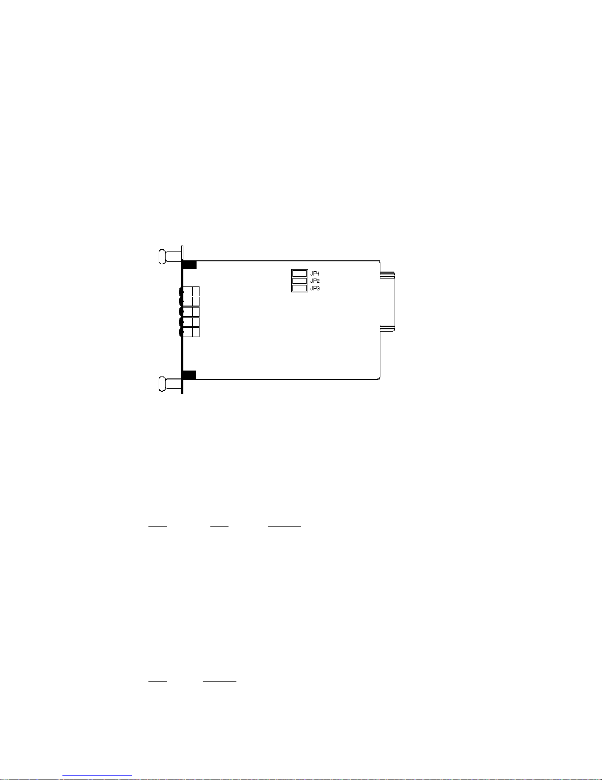
3.1 FRONT CARD SETTINGS
The jumpers on the Model 1110ARC “brains” card set RTS/CTS
delay and carrier control. Figure 1 (below) shows their location on the
PC board.
JP1 and JP2: RTS/CTS Delay
The combined settings for jumpers JP1 and JP2 determine the
amount of delay between the time the Model 1110ARC “sees” RTS and
when it sends CTS.
JP1 JP2 Setting
Off Off No delay
On Off No delay
On On 9.0 mS
Off On 79.5 mS
JP3: Carrier Detect
The settings for jumper JP3 determines whether carrier detect is
enabled or disabled. Carrier detect feature responds to RTS; if RTS is
on, the Model 1110ARC will have a carrier.
JP3 Setting
On Enabled
Off Disabled
Figure 1. Model 1110ARC front card jumper locations
Page 6

Page 7

DTE Shield (Pin 1) & FRGND (JB1)
In the connected (closed) position, this strap links DB-25 pin 1 and
frame ground. In the open (disconnected) position, pin 1 is “lifted” from
frame ground.
JB1
Position 1&2 = DTE Shield (Pin 1) and FRGND connected
Position 2&3 = DTE Shield (Pin 1) and FRGND
not connected
Page 8

Page 9

Switching the Power Supply On and Off
The power supply on/off switch is located on the front panel.
When plugged in and switched on, a red front panel LED will glow.
Since the Model 1000R16 is a “hot swappable” rack, it is not necessary
for any cards to be installed before switching on the power supply. The
power supply may be switched off at any time without harming the
installed cards.
NOTE: Please refer to the Model 1000RP Series User Manual AC
and DC Rack Mount Power Supplies for fuse and power card
replacement information.
4.2 INSTALLING THE MODEL 1110ARC INTO THE CHASSIS
The Model 1110ARC is comprised of a front card and a rear card.
The two cards meet inside the rack chassis and plug into each other
via mating 50 pin card edge connectors. Use the following steps as a
guideline for installing each Model 1110ARC into the Model 1000R16
rack chassis:
1. Slide the rear card into the back of the chassis along the metal
rails.
2. Secure the rear card using the metal screws provided.
3. Slide the front card into the front of the chassis. It should meet the
rear card when it’s almost all the way into the chassis.
4. Push the front card gently into the card-edge receptacle of the
rear card. It should “click” into place.
5. Secure the front card using the thumb screws.
Note: Since the Model 1000R16 chassis allows “hot swapping” of
cards, it is not necessary to power down the rack when you install or
remove a Model 1110ARC.
4.3 WIRING UP THE MODEL 1110ARC
Both of the rear interface cards compatible with the Model
1110ARC have one RS-232 port and one dual-connector fiber port.
Depending upon the card you have, the fiber port will be either an ST
or SMA connector. The RS-232 port is always a female HD-26
connector.
Page 10

Page 11

5.0 OPERATION
Once you have configured each Model 1110ARC and connected the
cables, you are ready to operate the units. This section describes the
LED status monitors and power-up procedure.
5.1 LED STATUS MONITORS
The Model 1110ARC features nine front panel status LEDs that
indicate the condition of the modem and communication link:
• The green “PWR” LED glows when power is applied to the modem
card through its mid-plane chassis connection.
• The green “TD” and “RD” indicators blink to show positive state
data activity. The Red “TD” and “RD” indicators blink to show
negative state data activity. Solid red indicates an idle state.
• The green “RTS” and “CD” indicators glow solid to show the
control signal is on. The red “RTS” and “CD” indicators glow solid
to show the control signal is off. When the 1110ARC is connected
to a DTE, RTS will glow green for an incoming signal on RS-232
pin 4. CD will glow green for an incoming signal from the line, and
an outgoing signal on RS-232 pin 8.
5.2 POWER-UP
There is no power switch on the Model 1110ARC: Power is
automatically applied to the 1110ARC when its card-edge connector
makes contact with the chassis’ mid-plane socket, or when the chassis’
power supply is turned on. Note: The 1110ARC is a “hot swappable”
card—it will not be damaged by plugging it in or removing it while the
rack is powered up.
When the local and remote units are both powered up, and are
passing data normally, the following LED conditions will exist:
• PWR = green
• TD & RD = flashing red and green
• RTS & DCD = green
Page 12

Page 13

APPENDIX B
PATTON MODEL 1110ARC FACTORY REPLACEMENT PARTS
The Patton Model 1110ARC rack system features interchangeable
rear half cards, power cords/fuses for international various operating
environments and other user-replaceable parts. Model numbers and
descriptions for these parts are listed below:
Patton Model # Description
1000RPEM..........................120/240V Rear Power Entry Module
1000RPSM-2.......................120/240V Front Power Supply Module
1000RPEM-DC ...................DC Rear Power Entry Module
1000RPSM-48A..................48V Front Power Supply Module
1000RPEM-V ......................120/240V CE Compliant Rear Power
Entry Module
1000RPSM-V ......................120/240V CE Compliant Front Power
Supply Module
0805US ...............................American Power Cord
0805EUR.............................European Power Cord CEE 7
0805UK...............................United Kingdom Power Cord
0805AUS.............................Australia/New Zealand Power Cord
0805DEN.............................Denmark Power Cord
0805FR ...............................France/Belgium Power Cord
0805IN.................................India Power Cord
0805IS.................................Israel Power Cord
0805JAP..............................Japan Power Cord
0805SW ..............................Switzerland Power Cord
05R16FPB1.........................Single Width Blank Front Panel
05R16FPB4.........................4-Wide Blank Front Panel
05R16RPB1 ........................Single Width Blank Rear Panel
05R16RPB4 ........................4-Wide Blank Rear Panel
0821R4................................400 mA Fuse (5x20mm)
Littlefuse 239.400 or equivalent
0821R2................................200 mA Fuse (5x20mm)
Littlefuse 239.200 or equivalent
056S1..................................Set of 16 #4 pan head screws/washers
Page 14

Page 15

APPENDIX C
PATTON MODEL 1110ARC BLOCK DIAGRAM
Copyright © 1998
Patton Electronics Company
All Rights Reserved
14
Page 16

 Loading...