

Page 1
USER
MANUAL
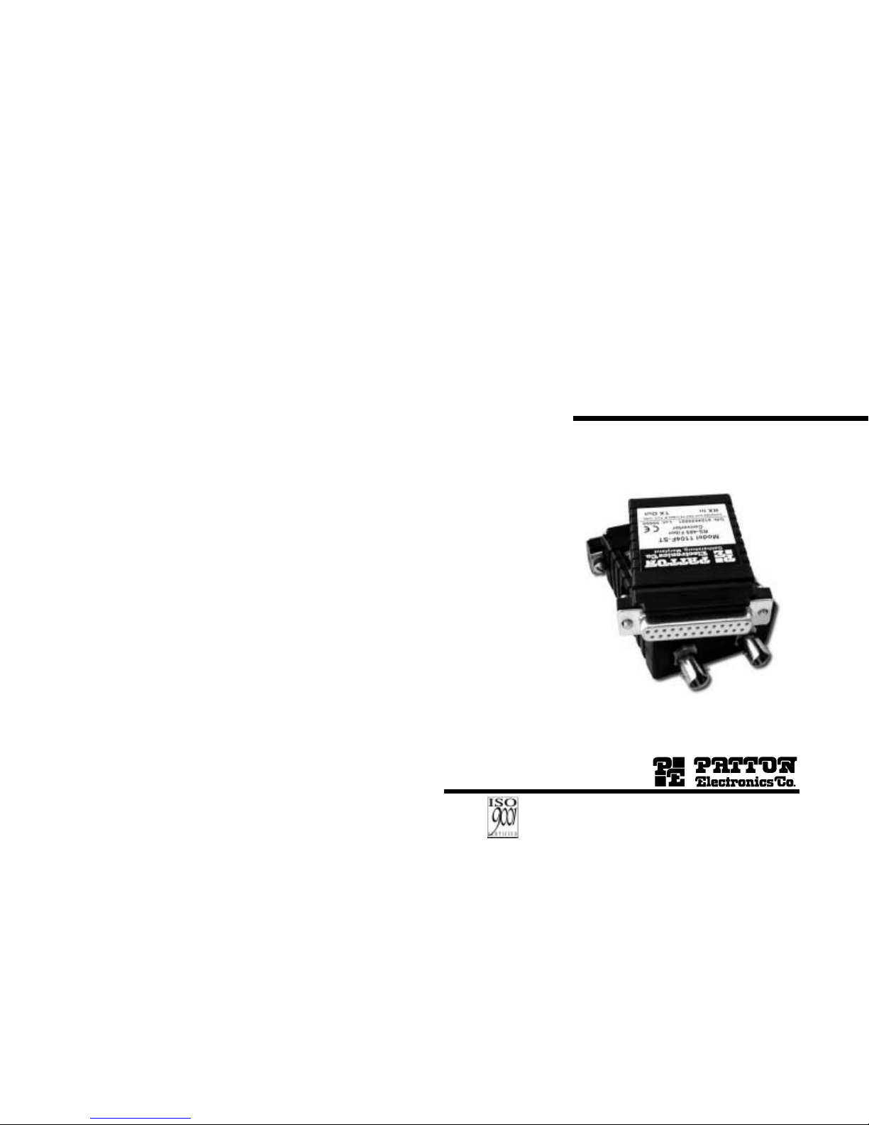
MMOODDEELL 11110044
SSEERRIIEESS
RS-485 Fiber Converter
SALES OFFICE
(301) 975-1000
TECHNICAL SUPPORT
(301) 975-1007
http://www.patton.com
Part# 07M1104-A
Doc# 018071UA
Revised 04/17/01
An ISO-9001
Certified Company
Page 2

1 2
Table of Contents
Section Page
1.0 Warranty Information.............................................................2
1.1 Radio and TV Interference
1.2. CE Notice
1.3 Service
2.0 General Information...............................................................4
2.1 Features
2.2 Description
3.0 Installation .............................................................................5
3.1 Power Connection
3.2 Installing the Model 1104F-ST/1104M-ST
3.3 Installing the Model 1104TB-ST
Appendix A - Specifications..........................................................7
Appendix B - Pin Out Configuration .............................................8
1.0 Warranty Information
Patton Electronics warrants all Model 1104 components to be free
from defects, and will—at our option—repair or replace the product should
it fail within one year from the first date of shipment.
This warranty is limited to defects in workmanship or materials,
and does not cover customer damage, abuse or unauthorized modification. If this product fails or does not perform as warranted, your sole
recourse shall be repair or replacement as described above. Under no
condition shall Patton Electronics be liable for any damages incurred
by the use of this product. These damages include, but are not limited
to, the following: lost profits, lost savings and incidental or consequential damages arising from the use of or inability to use this product.
Patton Electronics specifically disclaims all other warranties,
expressed or implied, and the installation or use of this product shall
be deemed an acceptance of these terms by the user.
1.1 Radio and TV Interference
The Model 1104 generates and uses radio frequency energy, and if not
installed and used properly—that is, in strict accordance with the manufacturer's instructions—may cause interference to radio and television
reception. The Model 1104 has been tested and found to comply with
the limits for a Class A computing device in accordance with the specifications in Subpart J of Part 15 of FCC rules, which are designed to
provide reasonable protection from such interference in a commercial
installation. However, there is no guarantee that interference will not
occur in a particular installation. If the Model 1104 does cause interference to radio or television reception, which can be determined by disconnecting the unit, the user is encouraged to try to correct the interference by one or more of the following measures: moving the computing equipment away from the receiver, re-orienting the receiving
antenna and/or plugging the receiving equipment into a different AC
outlet (such that the computing equipment and receiver are on different
branches).
1.2 CE Notice
The CE symbol on your Patton Electronics equipment indicates
that it is in compliance with the Electromagnetic Compatibility (EMC)
directive and the Low Voltage Directive (LVD) of the European Union
(EU). A Certificate of Compliance is available by contacting Technical
Support.
Page 3

3
4
1.3 Service
All warranty and non-warranty repairs must be returned freight
prepaid and insured to Patton Electronics. All returns must have a
Return Materials Authorization number on the outside of the shipping
container. This number may be obtained from Patton Electronics
Technical Support at:
tel: 301-975-1007
email: support@patton.com
www: http://www.patton.com
Patton Electronics' technical staff is also available to answer any
questions that might arise concerning the installation or use of your
Model 1104. Technical Support hours: 8AM to 5PM EST, Monday
through Friday.
NOTE: Packages received without an RMA number will not be
accepted.
2.0 General Information
Thank you for your purchase of this Patton Electronics product.
This product has been thoroughly inspected and tested and is warranted for One Year parts and labor. If any questions or problems arise
during installation or use of this product, please do not hesitate to contact Patton Electronics Technical Support at (301) 975-1007.
2.1 Features
- Asynchronous, RS-485 Operation
- Half Duplex over 2 wire lines
- Supports Data rates to 115Kbps
- Range up to 1.25 Miles (2km) over Dual Multimode Fiber
- ST Fiber Connectors
2.2 Description
The Model 1104 is a miniature, fiber optic converter that supports the
connection of RS-485 devices over multi-mode fibers.The unit provides the
capability of transmitting an RS-485 signals via a fiber optic link.The 1104
will be primarily used for data transmission in industrial and utility applications.The asynchronous data rate can be up to 115.2 Mbps in half-duplex
mode.The miniature size of the Model 1104 allows it to fit in tight installation spaces.On the fiber side, the Model 1104 features ST connectors.The
following versions of the 1104 are available:
1104M-ST/1104F-ST
- Dual multimode fiber with ST connections
- Male or Female DB25 connectors for RS-485 side
1104TB-ST
- Dual multimode fiber with ST connections
- Two position terminal block for RS-485 side
Page 4

5 6
3.0 Installation
The Model 1104 is designed for 2-wire, asynchronous, half duplex
communication.This section tells you how to connect and install the
following:
- Model 1104F-ST/1104M-ST
- Model 1104TB-ST
Refer to the appropriate section on the following page to install
your unit.
3.1 Power Connection
The Model 1104 comes with an AC power supply. The Model 1104
uses 9VDC, 500mA output,universal input power supply. The unit powers up as soon as it is plugged into an AC outlet. On Models 1104FST/1104M-ST, power can supplied via the DB25 connecter as indicated below.Using the Patton Model 3P-MF power suplly adapter.
3.2 Installing the Model 1104F-ST/1104M-ST
1) Refer to the pin configuration below when assembling the cable
that will connect to the DB25 connector.
DB25 Pin Out
Function
2 Data I/O 14 Data I/O +
9 +9VDC
7 GND
2) Plug in the DB25 connector.
3) Connect the fiber optic cables to the TX Out and RX in connectors.
3.3 Installing the Model 1104TB-ST
1) Strip the outer jacket insulation from the twisted pair
cable about 1 inch.
2) Strip back the insulation on each of the wires about .25
inches.
3) Connect the pair of wires to the + and - positions of the
terminal block.
4) Connect the fiber optic cables to the TX Out and RX in
connectors.
Page 5

8
Appendix A
Specifications
Transmission Line: Dual multi-mode optical cable, optimized to
work with 62.5/125 micron fiber-wavelength
850nm
RS-485 Interface: DB-25F, DB-25M or Terminal Block
DB-25: Pin 2, data I/O - ;Pin 14, Data I/O +
Transmission Mode: Asynchronous, half duplex
Fiber Interface: Dual ST connectors
Speed: 0-115Kbps
Range: Up to 1.25 miles (2km)
Power Budget: 12dB with 62.5/125 fiber
Power: External Universal Power Supply(100-250
VAC)
Compliance: FCC Part 15, CE
Temperature: 0-50 C
Humidity: 5-95 percent, non-condensing
Dimensions: 3.55” x 2.1” x .8”
7
Appendix B
Pin Out Configurations
DB-25 Pin # RS-485 Data
2.......................................................................data I/O -
14......................................................................data I/O +
T
erminal Block
RS-485 Data
+......................................................................data I/O -
-.......................................................................data I/O +
Fiber end is equipped with ST type fiber optic connectors
Page 6

 Loading...