

Page 1
USER
MANUAL
MODEL 1092RC
High Speed, 2-Wire,
Synchronous and
Asynchronous
Rack Mount Modem Card
SALES OFFICE
(301) 975-1000
TECHNICAL SUPPORT
(301) 975-1007
http://www.patton.com
Part# 07M1092RC-E
Doc# 033021U,
Rev. F
Revised 1/22/08
CERTIFIED
An ISO-9001
Certified Company
Page 2

TABLE OF CONTENTS
Section Page
1.0 Warranty Information .............................................................2
1.1 Radio and TV Interference
1.2 CE Notice
1.3 Service Information
2.0 General Information...............................................................4
2.1 Features
2.2 Description
3.0 Configuration .........................................................................5
3.1 Configuring the Hardware Switches
3.1.1 Reversible Interface Driver Board
3.1.2 Configuration Switch Set “S1”
3.1.3 Configuration Switch Set “S2”
3.2 Configuring the Software Switches
3.2.1 Configuring the Local 1092RC
3.2.2 Configuring the Remote 1092RC
3.3 Configuring the Rear Interface Card
3.3.1 Model 1000RCM12592 Strap Settings
3.3.2 Model 1000RCM13492 Strap Settings
4.0 Installation ...........................................................................24
4.1 The Model 1000R16P Rack Chassis
4.1.1 The Rack Power Supply
4.2 Installing the Model 1092RC Series Into Chassis
4.3.1 Connecting to a “DTE” Device
4.3.2 Connecting to a “DCE” Device
4.3.3 Connecting the Twisted Pair Interface
4.3 Wiring the Model 1092RC Series
5.0 Operation.............................................................................28
5.1 LED Status Indicators
5.2 Test Modes
5.2.1 using Local Line Loopback (LLB)
5.2.2 Using Remote Digital Loopback (RDL)
5.2.3 Using the V.52 (BER Test Pattern Generator
Appendix A - Specifications ........................................................32
Appendix B - Factory Replacement Parts and Accessories .......33
Appendix C - Terminal Interface Pin Assignments......................34
Appendix D - Control Port Pin Assignments ...............................36
Appendix E - Line Interface Pin Assignments.............................37
1
Page 3

Page 4

1.3 SERVICE
All warranty and nonwarranty repairs must be returned freight
prepaid and insured to Patton Electronics. All returns must have a
Return Materials Authorization number on the outside of the shipping
container. This number may be obtained from Patton Electronics
Technical Support:
tel: (301) 975-1007;
email: support@patton.com.
www: http://www.patton.com.
NOTE: Packages received without an RMA number will not be
accepted.
Patton Electronics' technical staff is also available to answer any
questions that might arise concerning the installation or use of your
Model 1092RC. Technical Service hours: 8AM to 5PM EST, Monday
through Friday.
3
Page 5

Page 6
3.0 CONFIGURATION
This section describes the location and orientation of the Model
1092RC’s configuration switches and jumpers, and provides detailed
instructions for all possible settings.
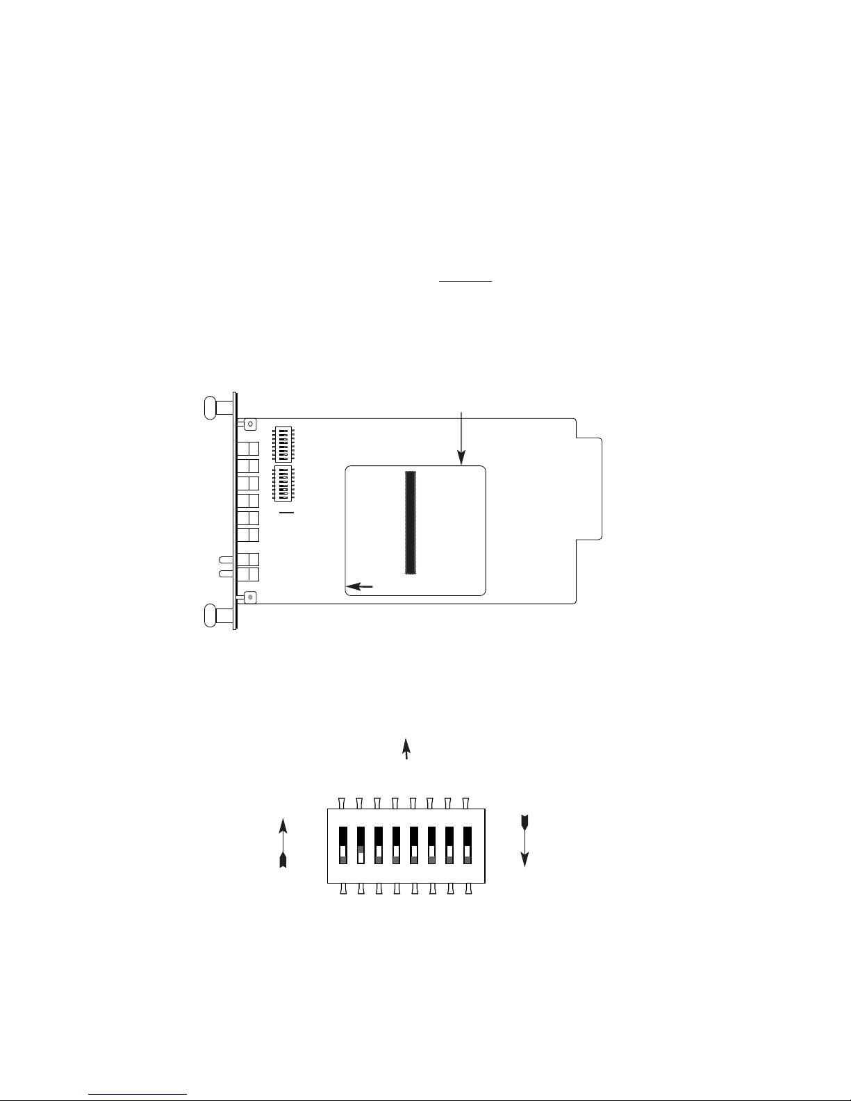
3.1 CONFIGURING THE HARDWARE SWITCHES
The Model 1092RC Series front card defaults
to the use of
hardware switches for configuration. There is an interface driver board
strap, and two eight-position DIP switches, on the front card (see
Figure 1, below).
Figure 2 shows the orientation of the DIP switches with respect to
the “ON” and “OFF” positions.
5
ON
12345678
ON
12345678
Figure 1. Model 1092RC, showing configuration switches and interface board
SW1
SW2
Interface
Driver
Board
THIS SIDE UP FOR V.35
FRONT
Figure 2. Close up of configuration switches (both sets are identical in appearance)
NOTE: The ON position is oriented toward the front of the Model 1092RC.
ON
12345678
OFF
ON
Front Panel
ON OFF
Page 7

Page 8

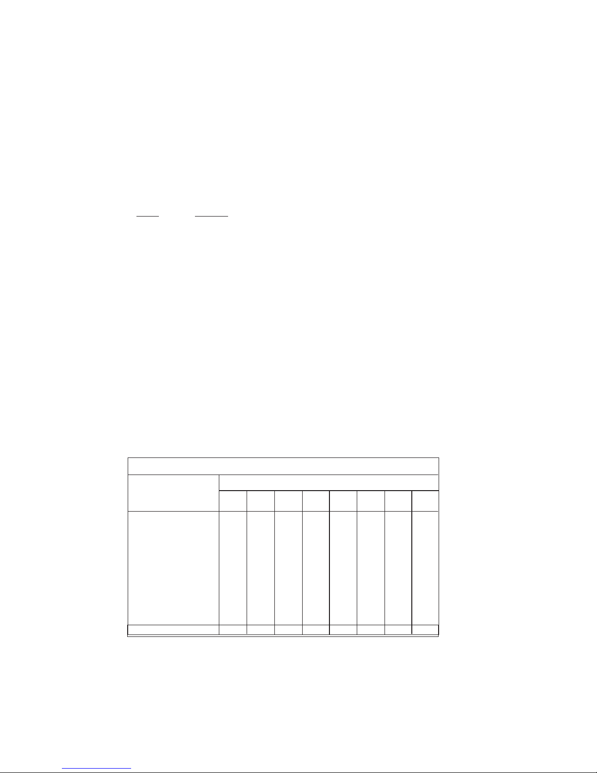
3.1.2 Configuration DIP Switch Set “S1”
The configuration switches on S1 allow you to specify the data
rate, async/sync data format, transmit clock source and response to
RDL request. Default settings of S1 are shown in the table below.
Switches S1-1 and S1-2: Data Rate
Use Switches S1-1and S1-2 to configure the data rate of the Model
1092RC. Each setting represents one synchronous data rate and one
asynchronous data rate.
S1-1
S1-2 Sync Data Rate Async Data Rate
On On 32 Kbps Reserved
Off On 56 Kbps Reserved
On Off 64 Kbps Reserved
Off Off 19.2 or 128 Kbps* 0 - 38.4 kbps
*NOTE: Model 1092RC operates either at a synchronous rate of
19.2 kbps
or
128 kbps depending on the orientation of Switch S2.
To operate synchronously at 19.2 kbps, set Switch S2-1 ON. To
operate at 128 kbps, set Switch S2-1 OFF. See Section 3.1.3 for
more information.
7
Position Function Factory Default
S1-1 Data Rate On
S1-2 Data Rate Off
S1-3 DSR during Local Line Loop On
S1-4 Async/Sync Data Format Off
S1-5 Async/Sync Data Format Off
S1-6 Tx Clock Source On
S1-7 Tx Clock Source On
S1 SUMMARY TABLE
64K Sync
}
}
Async/Sync
Internal Clock
}
DSR Enable
Page 9

Page 10
Switch S1-8: Respond to Local and Remote Loop from DTE
Use Switch S1-8 to determine whether the DTE can initiate a local
or remote loopback test. When Switch S1-8 is in the On position, the
DTE may activate a local or remote loopback test by raising the
appropriate interface signal (see Appendix C to determine the local and
remote loopback signals).
S1-8
Setting
On Respond to loop request from DTE Interface
Off Do not respond to loop request from DTE Interface
3.1.3 DIP Switch Set “S2” - Control Port Address and 19.2 kbps
Sync.
The Model 1092RC may be configured by a menu-driven software
system when used with the Patton Model 1000CC (for ordering
information, see Appendix B). In order to configure the Model 1092RC
by software commands, you must set its control port address.
The control port address is defined by a two digit decimal number.
Switches S2-1 through S2-4 define the least significant digit or the
“ones” digit, and Switches S2-5 through S2-7 define the “tens” digit.
Valid addresses are 0 through 79. Use the table below and the
instructions that follow the table to set the the control port to the desired
address.
9
S2 SUMMARY TABLE
Switch S2 Settings
1*2 345678
Address
Digit
0ONONONON
ON ON ON ON
1
OFF ON ON ON
OFF ON ON ON
2 ON OFF ON ON ON OFF ON ON
3 OFF OFF ON ON OFF OFF ON ON
4 ON ON OFF ON ON ON OFF ON
5 OFF ON OFF ON OFF ON OFF ON
6 ON OFF OFF ON ON OFF OFF ON
7 OFF OFF OFF ON OFF OFF OFF ON
8 ON ON ON ON N/A N/A N/A ON
NOTE: Default Settings Shown in Bold Italics; Default Address is “10”
Page 11

Page 12

3.2 CONFIGURING THE SOFTWARE SWITCHES
The Model 1092RC features a menu-driven command system that
allows you to configure either the local or remote 1092RC. The
software control port signals of the 1092RC are carried to each card in
the rack along the internal power bus board. Access to all rack card
control ports is provided by a single PATTON Model 1000CC Control
Card (see Model Model 1000CC User Manual). After setting the
control port address (Section 3.1.3), use the following instructions to
configure the unit:
1) Connect the serial RS-232 port of a V100 or similar DTE with
terminal emulation to the EIA-561 control port on the Model
1000CC control card. To construct an RS-232 to EIA-561
patch cable, refer to the control port pinout diagram in
Appendix D. Refer to Appendix C to order a pre-made cable.
2) Power up the terminal and set its RS-232 port as follows:
9600 Baud
8 data bits, i stop bit, no parity
Local echo
CR-CR/LF on inbound data
ANSI, VT-100 emulation
3. Press [CTRL+B] on the terminal followed by the two-digit
control port address and press [RETURN].
4. To make a selection from any menu, enter the option number.
To exit any menu without making a selection, press the [ESC]
key or the [SPACE] key.
5) After the Model 1092RC is powered on, the control port will
send out this message:
2W BBMRC, ver. x.x
6) Press [ESC] on the terminal.
7) The 1092RC will then display the MAIN MENU screen. You
may configure the LOCAL Model 1092RC from this screen.
To configure the REMOTE Model 1092RC, press ‘$’ (Shift-4
on most keyboards).
11
Important!!:
To make a selection from any menu, enter the option
number. To exit any menu without making a selection, or to return
to the previous menu, press the [ESC] key or the [SPACE] key.
Page 13

Page 14

MAIN MENU Option 3: Display Software Configuration
Select Option 3 to display the configuration of the software
switches. To use the software configuration for the Active
Configuration, select MAIN MENU, Option 5. Then select “Use
Software Switches”. Finally, select MAIN MENU Option 8 to save.
MAIN MENU Option 4: Setup Software Configuration
Select Option 4 toedit the software configuration of the Model
1092RC. To save changes after editing the software configuration,
select MAIN MENU Option 5, then select “Use Software Switches” and
then select MAIN MENU Option 8.
1. DTE Rate
Select Option 1 in the SOFTWARE CONFIGURATION menu to select
the async. or sync. DTE Rate of the Model 1092RC. Different DTE
Rate menu screens will display for async. or sync. bit rates. The
selections are shown below.
a) This menu is displayed when the data format is synchronous:
13
Page 15

Page 16

4. DSR During Local Line Loop
Select Option 4 in the SOFTWARE CONFIGURATION to configure
the behavior of the local Data Set Ready (DSR) signal during the Local
Line Loop test mode (below).
5. Response to Remote Digital Loop
Select Option 5 in the SOFTWARE CONFIGURATION Menu to
instruct the Model 1092RC to either respond or ignore the Remote
Digital Loop request from the remote 1092RC.
6. DTE Controlled Local Line Loop
Select Option 6 in the SOFTWARE CONFIGURATION Menu to
instruct the Model 1092RC to either respond or ignore Local Line Loop
requests from the DTE. To instruct the Model 1092RC to respond to
Local Line Loop requests from the DTE, select Enable (Option 1). To
instruct the 1092RC to ignore Local Line Loop requests from the DTE
interface, select Disable (Option 2).
15
Page 17

Page 18

Valid Model 1092RC Handshake status conditions are listed
below:
1. Handshaking - This status occurs when the 1092RC is in
the process of establishing a link with another 1092RC.
2. Data Mode - This status occurs when the 1092RC
successfully establishes a link with another 1092RC allowing
the data to flow.
3.2.7 MAIN MENU Option 7: Test Modes
Select Option 7 from the MAIN MENU to select the test mode status
of the Model 1092RC. (below). The Model 1092RC Test Mode settings
help to verify the integrity of the data link and isolate communication
difficulties.
NOTE: The 1092RC control port displays an error counter in
all test modes except options 4 and 7 listed above.
To run or terminate a particular test, key in the option to get to that
screen menu. If a particular test cannot be invoked, the unit displays
the message:
“Attempt unsuccessful!”.
17
Page 19

Page 20

3.2.2 Configuring the Remote 1092RC
To configure the remote 1092RC, make a selection from the
following REMOTE UNIT CONFIGURATION MAIN MENU. To return to
the LOCAL 1092RC MAIN MENU screen, press [ESC] and refer to
Section 3.2.1.
REMOTE MAIN MENU Option 1: Display Remote Unit Configuration
Select Option 1 to display the configuration of various parameters in
the remote Model 1092RC.
19
REMOTE UNIT CONFIGURATION
MAIN MENU
1. Display Remote Unit Configuration
2. Setup Remote Unit Configuration
3. Display Remote Modem Status
4. Select Hardware /Software Control
5. Restart Remote Unit
REMOTE CONFIGURATION
CONFIGURATION DISPLAY MENU
1. Display Configuration of:
DSR during Local Line Loop
Response to Remote Digital Loop
Clock Mode
2. Display Configuration of:
Configuration Control
DTE Rate
3. Display Configuration of:
DTE Controlled Local Line Loop
DTE Controlled Remote Digital Loop
Page 21

Page 22

3.3 CONFIGURING THE REAR INTERFACE CARD
The Model 1092RC Series has two interface card options: the
Model 1000RCM12592 (DB-25/RJ-45) and the Model 1000RCM13492
(M/34/RJ-45). Each of these options supports one DTE interface
connection and one 2-wire line connection. Figure 4 below illustrates
the two different interface options for the Model 1092RC Series.
NOTE: The 1092RC Series rear cards are specifically designed to
operate with the Model 1092RC function card and must not be
swapped with other Patton function cards.
Prior to installation, you will need to examine the rear card you
have selected and make sure it is properly configured for your
application. Each rear card is configured by setting straps located on
the PC board. To configure the rear cards, you must set the
configuration straps. Figure 5 below shows the orientation of these
straps. Each strap can either be on pegs 1 and 2, or on pegs 2 and 3.
Sections 3.3.1 and 3.3.2 describe the strap locations and possible
settings for each rear card.
21
Figure 4. Model 1092RC Series interface card options
DB-25 F
M/34 F
123 123 123
Figure 5. Orientation of Interface Card Straps
connected
open
RJ-45
RJ-45
Model
1000RCM12592
Model
1000RCM13492
Page 23

Page 24

SGND & FRGND (JB4)
In the connected position, this strap links DB-25 pin 7 (Signal
Ground) and frame ground. In the open position, pin 1 is disconnected
from frame ground.
JB4
Position 1&2 = SGND (Pin 7) and FRGND Connected
Position 2&3 = SGND (Pin 7) and FRGND Not Connected
3.3.2 Model 1000RCM13492 Strap Settings
Figure 7 shows the strap location for the Model 1000RCM13492
(M/34/RJ-45) rear card. This strap determines whether Signal Ground
and Frame Ground will be connected.
SGND & FRGND (JB4)
In the connected position, this strap links Signal Ground and frame
ground. In the open position, signal ground is disconnected from frame
ground.
JB4
Position 1&2 = SGND and FRGND Connected
Position 2&3 = SGND and FRGND Not Connected
23
Figure 7. M/34/RJ-45 strap locations
JB4
123
Page 25

Page 26

Switching the Power Supply On and Off
The power switch is located on the front panel. When plugged in
and switched on, a red front panel LED will glow. Since the Model
1000R16 is a "hot swappable" rack,
it is not necessary for any cards to
be installed before switching on the power supply
. The power supply
may be switched off at any time without harming the installed cards.
NOTE: Please refer to the Model 1000RP Series User Manual
AC
and DC Rack Mount Power Supplie
s for fuse and power card
replacement information.
4.2 INSTALLING THE MODEL 1092RC SERIES INTO THE CHASSIS
The Model 1092RC Series is comprised of a front card and a rear
card. The two cards meet inside the rack chassis and plug into each
other by way of mating 50 pin card edge connectors. Use the following
steps as a guideline for installing each Model 1092RC Series into the
rack chassis:
1. Slide the rear card into the back of the chassis along the metal
rails provided.
2. Secure the rear card using the metal screws provided.
3. Slide the front card into the front of the chassis. It should
meet the rear card when it’s almost all the way into the
chassis.
4. Push the front card
gently
into the card-edge receptacle of the
rear card. It should “click” into place.
5. Secure the front card using the thumb screws.
4.3 WIRING THE MODEL 1092RC SERIES
Each of the rear interface cards compatible with the Model
1092RC Series has one terminal interface port and one 2-wire (twisted
pair) port. For specific interface pin-outs, refer to the diagrams in
Appendix C of this manual.
.
25
Page 27

Page 28

4.3.4 Two-Wire Cable Connection Via RJ-45
1. The RJ-45 connector on the Model 1092RC’s twisted pair
interface is polarity insensitive and is wired for a two-wire
interface. The signal/pin relationships are shown in Figure 9
below.
2. Proper wiring of pairs between the two modems is as follows:
SIGNAL
PIN# PIN# SIGNAL
TIP 4--------------------------------------------- 4 TIP
RING 5--------------------------------------------- 5 RING
4.3.5 Connection to the Control Port Interface
Please refer to the Model 1000CC Control Card user manual for
cable requirements of the Control Port Interface.
27
Notice! Any modular twisted pair cable connected to
the Model 1092RC must be shielded cable, and the outer
shield must be properly terminated to a shielded modular
plug on both ends of the cable.
Figure 9. Model 1092RC twisted pair line interface.
1 (N/C)
2 (GND)
3 (N/C)
4 (Tip)
5 (Ring)
6 (N/C)
7 (GND)
8 (N/C)
1
2
3
4
5
6
7
8
Page 29

Page 30

ER glows red to indicate the likelihood of a Bit Error
in the received signal. During the 511 or 511/E
test, ER flashes to indicate that the Test Pattern
Detector has detected a bit error.
TM glows red to indicate that the Model 1092RC
has been placed in Test Mode. The unit can be
placed in test mode by the local user or by the
remote user.
NS (No Signal) glows red to indicate that the local
Model 1092RC has not yet connected with the
remote Model 1092RC.
5.2 TEST MODES
The Model 1092RC offers two proprietary loopback test modes,
plus a built-in V.52 BER test pattern generator, to evaluate the condition
of the modems and the communication link. These tests can be
activated physically from the front panel, or via the interface.
5.2.1 Using Local Line Loopback (LLB)
The Local Line Loopback (LLB) test checks the operation of the
local Model 1092RC, and is performed separately on each unit. Any
data sent to the local Model 1092RC in this test mode will be echoed
(returned) back to the user device (see Figure 11, below). For
example, characters typed on the keyboard of a terminal will appear on
the terminal screen.
To perform an LLB test, follow these steps:
1. Activate LLB. This may be done in one of two ways: First, by
moving the front panel toggle switch to the right to “Local”.
Second, by raising the LLB signal on the interface (see
Appendix C). Once LLB is activated, the Model 1092RC
transmitter output is connected to its own receiver. The “TM”
LED should be lit.
29
1090
Figure 11 Local Line Loopback
1092RC
Page 31

Page 32

5.2.3 Using the V.52 (BER) Test Pattern Generator
To use the V.52 BER tests in conjunction with the Remote Digital
Loopback tests* (or with Local Line Loopback tests), follow these
instructions:
1. Locate the “511/511E” toggle switch on the front panel of the
1092RC and move it to the left. This activates the V.52 BER
test mode and transmits a “511” test pattern into the loop. If
any errors are present, the local modem’s red “ER” LED will
blink sporadically.
2. If the above test indicates no errors are present, move the
V.52 toggle switch to the right, activating the “511/E” test with
errors present. If the test is working properly, the local
modem's red “ER” LED will glow. A successful “511/E” test
will confirm that the link is in place, and that the Model
1092RC’s built-in “511” generator and detector are working
properly.
*NOTE: The above V.52 BER tests can be used independently of
the Remote Digital Loopback tests. This requires two operators:
one to initiate and monitor the tests at the local Model 1092RC,
and one to do the same at the remote Model 1092RC. In this
case, the test pattern sent by each Model 1092RC will not be
looped back, but will be transmitted down the line to the other
Model 1092RC.
31
Page 33

Page 34

APPENDIX B
PATTON MODEL 1092RC
FACTORY REPLACEMENT PARTS
AND ACCESSORIES
Patton Model #
Description
1000RCM12592.........Rear card w/DB25F & RJ45 (V.24 interface)
1000RCM12492.........Rear card w/ M/34F & RJ45 (V.35 interface)
1000RPEM ................120/240V Rear Power Entry Module
1000RPSM-2 .............120/240V Front Power Supply Module
1000RPEM-DC..........DC Rear Power Entry Module
1000RPSM-48A.........48V Front Power Supply Module
1000RPEM-V.............120/240V CE Compliant Rear Power
Entry Module
1000RPEM-V.............120/240V CE Compliant Rear Power
Supply Entry Module
1000CC......................Control Card
IM1RC/A ....................Interface daughter card, V24/V.35
0805US......................American Power Cord
0805EUR ...................European Power Cord CEE 7
0805UK......................United Kingdom Power Cord
0805AUS ...................Australia/New Zealand Power Cord
0805DEN ...................Denmark Power Cord
0805FR......................France/Belgium Power Cord
0805IN .......................India Power Cord
0805IS .......................Israel Power Cord
0805JAP ....................Japan Power Cord
0805SW.....................Switzerland Power Cord
33
Page 35

Page 36

APPENDIX C (Continued)
PATTON MODEL 1092RC
TERMINAL INTERFACE PIN ASSIGNMENT
DB-25F Connector-DCE
(RS-232 Interface)
Pin #
Signal
1...........................FG (Frame Ground)
2.......................... TD (Transmit Data)
3...........................RD (Receive Data)
4...........................RTS (Request to Send)
5...........................CTS (Clear to Send)
6...........................DSR (Data Transfer Rate)
7...........................SGND (Signal Ground)
15.........................TC (Test Control-A)
17.........................RC (Receive Timing)
18.........................LLB (Local Line Loop)
20.........................DTR (Data Transfer Rate)
21.........................RDL (Remote Digital Loop)
24.........................XTC (External Transmit Clock
25.........................TM (Test Mode)
35
Page 37

Page 38

APPENDIX E
LINE INTERFACE PIN ASSIGNMENT
(RJ45 Connector)
Pin Number
Signal
1...................................................N/C (No Connection)
2...................................................N/C (No Connection)
3...................................................N/C (No Connection)
4...................................................Tip
5....................................................Ring
6....................................................N/C (No Connection)
7....................................................N/C (No Connection)
8....................................................N/C (No Connection)
© Copyright 1997
Patton Electronics Company
All Rights Reserved
37
Page 39

Page 40

 Loading...