

Page 1
USER
MANUAL
MODEL 1089/I
10BaseT HDSL
Rocket
Part# 07M1089/I-A
Doc# 032071UA
Revised 12/7/99
SALES OFFICE
(301)975-1000
TECHNICAL SUPPORT
(301)975-1007
http://www.patton.com
An ISO-9001
Certified
Company
Page 2

TTAABBLLEE OOFF CCOONNTTEENNTTSS
Section Page
1.0 Warranty Information.............................................................2
1.1 Radio and TV Interference
1.2. CE Notice
1.3 Service
2.0 General Information...............................................................4
2.1 Features
2.2 Description
3.0 Configuration .........................................................................5
3.1 Configuring the Hardware DIP Switches
3.1.1 Configuration DIP Switch Set “S2”
3.1.2 Configuration DIP Switch Set “S3”
4.0 Installation .............................................................................9
4.1 Connecting the DSL Interface
4.2 Connecting the 10BaseT Ethernet Port to PC (DTE)
4.3 Connecting the 10BaseT Ethernet Port to a Hub (DCE)
4.4 Connecting Power
4.3.1 Connecting to AC Power
4.3.2 Connecting to a DC Power
5.0 Operation .............................................................................12
5.1 Power-Up
5.2 LED Status Monitors
5.3 Test Modes
5.3.1 Overview
5.3.2 Loops and Patterns
5.3.3 Using the V.52 (BER) Test Pattern Generator
Appendix A - Specifications........................................................19
Appendix B - Factory Replacement Parts and Accessories.......20
Appendix D - Transmission Distance Chart ...............................21
1
11..00 WWAARRRRAANNTTYY IINNFFOORRMMAATTIIOONN
Patton Electronics warrants all Model 1089 components to be
free from defects, and will—at our option—repair or replace the product should it fail within one year from the first date of shipment.
This warranty is limited to defects in workmanship or materials,
and does not cover customer damage, abuse or unauthorized modification. If this product fails or does not perform as warranted, your sole
recourse shall be repair or replacement as described above. Under no
condition shall Patton Electronics be liable for any damages incurred
by the use of this product. These damages include, but are not limited
to, the following: lost profits, lost savings and incidental or consequential damages arising from the use of or inability to use this product.
Patton Electronics specifically disclaims all other warranties,
expressed or implied, and the installation or use of this product shall
be deemed an acceptance of these terms by the user.
1.1 RADIO AND TV INTERFERENCE
The Model 1089 generates and uses radio frequency energy, and
if not installed and used properly—that is, in strict accordance with the
manufacturer's instructions—may cause interference to radio and television reception. The Model 1089 has been tested and found to comply with the limits for a Class A computing device in accordance with
the specifications in Subpart J of Part 15 of FCC rules, which are
designed to provide reasonable protection from such interference in a
commercial installation. However, there is no guarantee that interference will not occur in a particular installation. If the Model 1089 does
cause interference to radio or television reception, which can be determined by disconnecting the unit, the user is encouraged to try to correct the interference by one or more of the following measures: moving the computing equipment away from the receiver, re-orienting the
receiving antenna and/or plugging the receiving equipment into a different AC outlet (such that the computing equipment and receiver are
on different branches).
1.2 CE NOTICE
The CE symbol on your Patton Electronics equipment indicates
that it is in compliance with the Electromagnetic Compatibility (EMC)
directive and the Low Voltage Directive (LVD) of the European Union
(EU). A Certificate of Compliance is available by contacting Technical
Support.
2
Page 3

1.3 SERVICE
All warranty and non-warranty repairs must be returned freight
prepaid and insured to Patton Electronics. All returns must have a
Return Materials Authorization number on the outside of the shipping
container. This number may be obtained from Patton Electronics
Technical Service at:
tel: (301)975-1007
email: support@patton.com
www: http://www.patton.com
Patton Electronics' technical staff is also available to answer any
questions that might arise concerning the installation or use of your
Model 1089. Technical Service hours: 8AM to 5PM EST, Monday
through Friday.
3
22..00 GGEENNEERRAALL IINNFFOORRMMAATTIIOONN
Thank you for your purchase of this Patton Electronics product.
This product has been thoroughly inspected and tested and is warranted for One Year parts and labor. If any questions or problems arise
during installation or use of this product, please do not hesitate to contact Patton Electronics Technical Support at (301) 975-1007.
2.1 FEATURES
• Provides MAC Level (Layer 2) connection between 2 peered
10BaseT Ethernet LANs
• Operates transparently to higher level protocols such as TCP/IP,
DECnet, NETBEUI and IPX
• Automatically discovers, loads and deletes MAC addresses
• Point-to-Point Connectivity over 2-Wire HDSL up to 5km
• HTTP/SNMP Manageable as CP (Customer Premises) Unit with
1094ARC CO (Central Office) Rack Card
• Internal or receive recovered clocking between units
• LED indicators for 10BaseT Link, DSL Link, Status, No Signal,
Error and Test Mode
2.2 DESCRIPTION
The
NetLink
TM
10BaseT HDSL Rocket
(Model 1089) is a MultiRate DSL Modem that provides seamless MAC Layer connectivity
between 2 peered 10BaseT LANs. Now, Enterprise users no longer
need to hassle with a bridge
and
a CSU/DSU or recurring leased line
costs. The NetLink Rocket allows users to add additional nodes to a
LAN that has reached its maximum distance limits or separate high
traffic areas of a LAN. The Rocket connects peered LANs and automatically forwards and receives LAN broadcasts, multi-casts and
frames across a 2-Wire DSL span.
The
NetLink
TM
HDSL 10BaseT Rocket
features include loopback
diagnostics, inband SNMP/HTTP remote management capabilities
using NetLink Plug-and-Play and externally accessible configuration
switches. As a symmetric DSL modem, the
NetLink
TM
HDSL Rocket
offers the same data rates in both directions over a single pair of regular telephone lines using 2B1Q modulation. The Rocket connects to
the DSL line via an RJ-45 jack. Standard power options include
115VAC, 230VAC, Universal (100/240VAC) and any DC input between
36-60VDC.
4
NOTE: Packages received without an RMA number will not be
accepted.
Page 4
33..00 CCOONNFFIIGGUURRAATTIIOONN
The Model 1089 has two sets of eight DIP switches, which allow
configuration for a wide variety of applications. This section describes
switch locations and explains all settings.
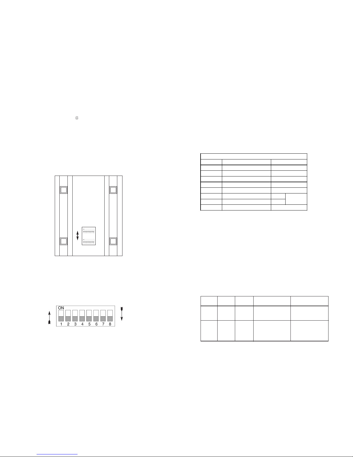
3.1 CONFIGURING THE HARDWARE DIP SWITCHES
The 16 external switches are grouped into two eight-switch sets,
and are externally accessible from the underside of the Model 1089, as
shown in Figure 1, below).
The two sets of DIP switches on the underside of the Model 1089
will be referred to in this manual as S2 and S3. As Figure 2 shows,
the orientation of all DIP switches is the same with respect to “ON” and
“OFF” positions.
5
Figure 2. Close Up of Configuration Switches (all sets are identical in appearance)
3.1.1 Configuration DIP Switch Set “S2”
The only setting for S2 is for Clocking Mode between Model
1089s. All other switches are reserved for factory usage and must
remain in the default configuration. Default settings are shown in the
table below.
Switch S2-1, S2-2, S2-3, S2-4, S2-5 and S2-8:
Switches S2-1, S2-2, S2-3, S2-4, S2-5 and S2-8 are reserved for factory use and must remain in the factory default settings as shown in
the table above. .
Switches S2-6 and S2-7: Clock Mode
Use Switches S2-6 and S2-7 to configure internal, or receive
recover (clocking derived from the remote Model 1089 across the DSL
span) settings. One Model 1089 (typically the CO, or “Central Office”
unit) will be set for Internal Clock. The remote Model 1089 (typically
the CP, or Customer Premises unit) will be set for Receive Recover
clocking. The table below shows the clock mode settings.
6
Position Function
S2-1 Reserved
S2-2 Reserved
S2-3 Reserved
S2-4 Reserved
S2-5 Reserved
S2-6 Clock Mode On
S2-7 Clock Mode Off
S2-8 Reserved
Off
Off
Off
Receive
Recov er
Off
Off
Off
S2 SUMMARY TA BLE
Factory Default
OFF
ON
FRONT
REAR
Figure 1. Underside of Model 1089 Series, showing location of DIP switches
S2
S3
ON
OFF
CO/CP
Unit S2-6 S2-7 Clock Mode Description
Model 1089 gener-
CO On On Internal ates internal, crys
tal controlled timing.
Model 1089
CP On Off Receive Recover receives its timing
from the CO unit
over the DSL span.
Page 5

7
3.1.2 Configuration Switch Set “S3”
Use the DIP Switches in Switch S3 to set the DTE Rate (for LAN
Bandwidth Allocation), the transmit data sampling point and to reset
the unit to its software default settings. The following table summarizes default positions of DIP Switch S3. Detailed descriptions of each
switch follow the table.
Switch S3-1 through S3-6: DTE Rate
Use Switch S3-1 through S3-6 to provision bandwidth to the LAN
in 64kbps increments up to 1.152Mbps. Peak bandwidth utilization on
the local domain on an Ethernet LAN runs typically between 15% to
20% (1.5Mbps to 2Mbps) of the maximum bit rate of 10Mbps. Traffic
between LANs typically runs even lower -- between 2% to 7%
(200kbps to 700kbps) of the maximum bit rate depending upon application and environmental conditions. This is the amount of traffic that
will run across the DSL span.
Set Switches 3-1 through S3-6 to allocate bandwidth based upon
expected LAN to LAN traffic rates. As an example, set applications
which low LAN to LAN bandwidth content between 64kbps and
576kbps. Applications with high bandwidth LAN to LAN content should
be set between 576kbps and 2.304Mbps as required.
S3-1
S3-2 S3-3 S3-4 S3-5 S3-6 DTE Rate (kbps)
Off Off On On On On 64
On On Off On On On 128
Off On Off On On On 192
On Off Off On On On 256
Off Off Off On On On 320
On On On Off On On 384
Off On On Off On On 448
On Off On Off On On 512
Off Off On Off On On 576
On On Off Off On On 640
Off On Off Off On On 704
On Off Off Off On On 768
Off Off Off Off On On 832
On On On On Off On 896
Off On On On Off On 960
On Off On On Off On 1024
Off Off On On Off On 1089
On On Off On Off On 1152
Switch S3-7: Reset Software Defaults
Use Switch S3-7 to reset the software configured factory defaults.
This feature is applicable only using the Model 1001MC to SNMP
manage your units. For more information, please refer to the Model
1001MC Operations Manual.
S3-7
Setting
On Normal Operation
Off Reset
Switch S3-8: Reserved
Switch S3-8 is reserved for factory use and must remain in the On
position.
8
S3 SUMMARY TABLE
Position Function Factory Default
S3-1 DTE Rate On
S3-2 DTE Rate Off
S3-3 DTE Rate Off
S3-4 DTE Rate Off
S3-5 DTE Rate On
S3-6 DTE Rate On
S3-7 Reset Software Defaults On
Normal Operation
S3-8
Reserved
On
}
768 kbps
NOTE: The Model 1089 will automatically select the optimum
line rate for the required distance based on the DTE rate set by
Switches S3-1 through S3-6. This selection is based on the lowest line rate that will support the DTE rate.
Page 6

9
44..00 IINNSSTTAALLLLAATTIIOONN
When the Model 1089 has been properly configured, it may be
connected to the DSL twisted pair interface, the 10BaseT Ethernet
Interface, and the power source. This section describes these connections.
4.1 CONNECTING THE DSL INTERFACE
The Model 1089 supports communication between 10BaseT Hubs
or Workstations at distances to 5 miles (8 km) over 24 AWG (.5mm)
twisted pair wire. Two things are essential:
1. These units operate as a pair. Both units at the end of the
twisted pair DSL span must be set for the same DTE rate.
2. To function properly, the Model 1089 needs one twisted pair of
metallic wire. This twisted pair must be unconditioned, dry, metal-
lic wire, between 19 (.9mm) and 26 AWG (.4mm) (the higher num-
ber gauges will limit distance). Standard dial-up telephone cir-
cuits, or leased circuits that run through signal equalization equip-
ment, or standard, flat modular telephone type cable,
will not work!
The RJ-45 connector on the Model 1089’s twisted pair interface is
polarity insensitive and is wired for a two-wire interface. The signal/pin
relationships are shown in Figure 4 below.
10
4.2 Connecting the 10Base-T Ethernet Port to a PC (DTE)
The 10Base-T interface is configured as DTE (Data Terminal
Equipment). If the Model 1089 is to to connect to another DTE device
such as a 10Base-T network interface card, construct a 10Base-T
crossover cable and connect the wires as shown in the diagram below.
10BaseT Port 10Base-T DTE
RJ-45 Pin No. RJ-45 Pin No.
1 (TX+) 1 (TX+)
2 (TX-) 2 (TX-)
3 (RX+) 3 (RX+)
6 (RX-) 6 (RX-)
4.3 Connecting the 10Base-T Ethernet Port to a Hub
The 10Base-T interface is configured as DTE (Data Terminal
Equipment), just like a 10Base-T network interface card in a PC.
Therefore, it “expects” to connect to a 10Base-T Hub using a straightthrough RJ-45 cable. Use the diagram below to construct a cable to
connect the 10 BaseT interface to a 10Base-T Hub.
10BaseT Port 10Base-T Hub
RJ-45 Pin No. RJ-45 Pin No.
1 (TD+) 1 (RD+)
2 (TD-) 2 (RD-)
3 (RD+) 3 (TD+)
6 (RD-) 6 (TD-)
Figure 4. Model 1089 twisted pair line interface.
10BaseT
Interface
1 (N/C)
2 (N/C)
3 (N/C)
4 (2-Wire TIP)
5 (2-Wire RING)
6 (N/C)
7 (N/C)
8 (N/C)
DSL Interface
1
2
3
4
5
6
7
8
1 TD+ (data output from 1089)
2 TD- (data output from 1089)
3 RD+ (data input to 1089)
4 (no connection)
5 (no connection)
6 RD- (data input to 1089)
7 (no connection)
8 (no connection)
1
2
3
4
5
6
7
8
Figure 5. Model 1089 10BaseT Ethernet RJ-45 Connector Pinout
Figure 3. Model 1089 Rear Panel
IMPORTANT!:
The Model 1089 has been optimized for per-
formance at high bitrates (DTE rates greater than 512 kbps). To
ensure accurate performance at these bit rates, please use twisted
pair line interface cable that is at least 330ft (100m) in length.
Page 7

11
4.4 POWER CONNECTION
Universal AC Power (100-240VAC)
The Model 1089 uses a 5VDC, 2A universal input 100-240VAC,
power supply (center pin is +5V). The universal input power supply
has a male IEC-320 power entry connector. This power supply connects to the Model 1089 by means of a barrel jack on the rear panel.
Many international power cords are available for the universal power
supply (Please refer to Appendix B for country-specific power cords.
The Model 1089 powers up as soon as it is plugged into an AC
outlet--there is no power switch.
120 VAC Power (US)
The 100-132 VAC adapter supplied with the U.S. version of the
Model 1089 is a wall mount type and may be plugged into any
approved 120 VAC wall jack.
230 VAC Power (International)
The 230 VAC adapter supplied with the International version of the
Model 1089 is a wall mount type and may be plugged into any
approved 230 VAC wall jack.
DC Power
The 36-60 VDC DC to DC adapter supplied with the DC version of
the Model 1089 plugs in a DC source (nominal 48VDC) and plugs into
the barrel power supply jack on the rear of the 1089/I. Please refer to
Figure 5, below, to make the proper connection.
55..00 OOPPEERRAATTIIOONN
When the Model 1089 has been properly configured and installed,
it should operate transparently. This sections describes power-up,
LED status monitors, and the built-in loopback test modes.
5.1 POWER-UP
Before applying power to the Model 1089, please read Section
4.3 and ensure that the unit is connected to the appropriate power
source.
5.2 LED STATUS MONITORS
The Model 1089 features six front panel LEDs that monitor connections on the DSL and 10BaseT links, signaling, error and test
modes. Figure 6 (below) shows the front panel location of each LED.
Descriptions of each LED follow Figure 6.
DSL Link (Active Green) Solid green (On) indicates that the
end to end DSL Framer Link is up, signifying that
the link across the DSL span is active. The DSL
Link LED is Off when the link is down.
Status Blinks yellow from one to eleven times to indicate
system status. Each pulse pattern is separated by
a 2 second “off” period. Greater pulse patterns
have higher priority (buffer saturation has greater
priority than an empty MAC table). Valid system
statuses are:
1 pulse = system status is okay
2 pulses = no MAC entries in the MAC
Address Table
3 pulses = Clear to Send (CTS) or Carrier
Detect (DCD) from base unit are not
asserted
4 pulses = IM1/I buffer is saturated
5 pulses = WAN receive frame(s) too large
6 pulses = WAN receive frame(s) not octet
aligned
12
WARNING! There are no user-serviceable parts in the
power supply section of the Model 1089. Contact Patton
Electronics Technical support at
(301)975-1007
, via our web
site at http://www.patton.com, or by e-mail at support@patton.com, for more information.
Figure 6. Connecting DC Power to the 48V-PSM DC Power Supply.
-Vin
To Power
Supply Jack
To -48VDC
Source
+Vin
Figure 7. Model 1088 Front Panel
Page 8

7 pulses = WAN receive frame(s) aborted
8 pulses = Detected WAN receive frame(s) with
CRC
9 pulses = Detected LAN receive frame(s) too large
10 pulses = Detected LAN receive frame(s) not octet
aligned
11 pulses = Detected LAN receive frame(s) with bad
CRC
10BT Link (Active Green) Solid green indicates that the
10BaseT Ethernet interface has detected a valid
SQE heartbeat, signifying a valid 10BaseT connection.
NS (Active Red) Solid red indicates that the Digital
Signal Processors (DSPs) are not linked.
ER (Active Red) Flashing red indicates CRC Errors on
DSL (Framer) side if DSL Link is active or if bit
errors are received during loop/BER test.
- ER flashes once to indicate a CRC error (during
normal operation) or bit errors (during Remote
Loopback 511/511E tests).
TM (Active Yellow) Solid Yellow indicates an Active
Test Mode. The unit may be placed in test mode
by the local user or by the remote user.
13
5.3 TEST MODES
The Model 1089 offers a proprietary Remote Loopback test
modes, plus a built-in V.52 BER test pattern generator to evaluate the
communication status between units. Activate this test mode by toggling the Test Mode Switch on the front panel of the unit.
5.3.1 Overview
Figure 8 below shows the major elements used in the loop-back
and 511 pattern tests available in the Model 1089. Each block has several functions. Following Figure 7 are descriptions of the elements during Test Modes.
Framer The framer determines the status of the line. In
normal operation the framer transmits and
expects to receive framed packets from the far
end. If the framer receives framed packets from
the far end, the DSL Link LED will turn on. If
framed packets are not received, the DSL Link
LED will turn off. The restart procedure uses this
information to determine if a valid connection is
made (cable disconnect, poor cable quality, etc).
In normal Data Mode, if the box receives 4 seconds of unframed packets it will restart the box
and begin trying to re-establish a connection
with the the remote Model 1089. The distinction
between framed packets and unframed packets
becomes important when we discuss the Pattern
Generator.
Pattern Gen/Det This part of the Processor generates and
detects the 511/511E patterns. When transmitting 511 patterns, the information is unframed
14
Pattern
Gen/Det
Loop
Contr
ol
Loop
Contro
l
Pattern
Gen/Det
Processor
Processor
Framer
Framer
DSL
Span
Figure 8: Block Diagram Two Model 1089s Communicating over the DSL Span
Page 9

(because it originates after the framer) and is
intended to be evaluated only by another
Processor. If the units are transmitting data and
the pattern generator is enabled on one end of
the link, the far end will begin receiving
unframed packets and assume that the line has
gone down. During test modes, the pattern generator is forced to time out before it can cause
the DSL link to go down.
Loop Control This part of the Processor is used to control
Remote Loopback test mode. In a Remote
Loop, the 511/511/E data is looped back to the
line and to the remote unit over the DSL span.
15
Restart Procedure The restart procedure is in place to allow the
and Time Outs units to re-establish a connection after the
framer begins seeing unframed packets. The
Test Mode Timing Chart below shows the
amount of time the framer must see consecutive
unframed packets before the unit will restart and
try to establish a new line connection. The reason that there are different Restart Times will
become apparent after reading the rest of the
document. The 511/511E Time Out shown refers
to the amount of time the 511/511E pattern will
be valid. At the end of this time the pattern will
automatically turn itself off and the normal data
path will be re-established. The ER led will flash
indicating to the user that the test has timed out.
The ER led will stop flashing once the 511/511E
switch is placed into the normal position.
Symbol Indicators
This symbol designates the origination or the
termination of a data path. The direction of the
arrow connected distinguish the two data paths.
This symbol designates an invalid data path. If
there is data present it should be ignored.
16
Test Mode Timing
Item Elapsed Time (seconds)
Start Up 50
Data Mode 4
511/511E Generator Enabled 60 (The generator will stop after 45 seconds.)
Remote End of an RDL 60
511/511E Time Out 45 (The pattern generator will automatically turn
off after 45 seconds. The ER LED will flash until
the user turns off the 511/511E switch.)
Page 10

5.3.2 Loops and Patterns
The following section describes the Remote Loopback/BER test
modes.
Remote Digital When Remote Loop/511 or Remote Loop/511/E
is enabled via the front panel switch, the
Remote unit’s Restart Timer is set to one
minute. This is because when the 511/511E
generator is initiated on the local unit, the
Remote framer begins seeing unframed packets. The Remote unit can not distinguish the
511/511E pattern from the line being disconnected, so the Restart Timer has been lengthened to
allow the pattern generator to function. Once the
511/511E test is started, the Local unit changes
its' Restart Timer to one minute. The pattern
originates within the Processor and is sent to
the Remote unit. It is then looped back to the
Local unit where it is evaluated for errors. After
45 seconds, the Pattern Generator will timeout
and stops sending the pattern. The ER led will
begin blinking until the user turns off the
511/511E switch.
5.3.3 The V.52 (BER) Test Pattern Generator
To use the V.52 BER tests in conjunction with the Remote Digital
Loopback tests, follow these instructions:
1. Locate the Remote Loop/511 & Remote Loop/511E toggle
switch on the front panel of the 1089 and move it DOWN.
This activates the Remote Loop with V.52 BER
and transmits a “511” test pattern into the loop. If any errors
are present, the local unit’s red “ER” LED will blink
sporadically.
17
2. If the above test indicates no errors are present, move the
test switch V.52 toggle switch UP, activating the “511/E” test
with intentional errors present. If the test is working properly,
the local unit’s red “ER” LED will blink. A successful “511/E”
test will confirm that the link is in place, and that the Model
1089’s built-in “511” generator and detector are working
properly.
18
Pattern
Gen/Det
Loop
Contr
ol
Loop
Contro
l
Pattern
Gen/Det
Processor
Processor
Framer
Framer
Line
Figure 9: Block Diagram Two Model 1089s Communicating over the DSL Span
Page 11

AAPPPPEENNDDIIXX AA
PPAATTTTOONN EELLEECCTTRROONNIICCSS MMOODDEELL 11008899
SSPPEECCIIFFIICCAATTIIOONNSS
Clocking Modes: Internal or Receive Recovered
DTE Rate: 64, 128, 192, 256, 320, 384,448, 512, 576,
640, 704, 768, 832, 896, 960, 1024, 1088,
and 1152 kbps
Line Rates (DSL line): 144, 272, 400, 528, 784, 1168 kbps
Transmission Line: Single Twisted Pair
Line Coding: 2B1Q
Line Interface: Transformer coupled, 1500 VAC isolation
Diagnostics: V52 compliant (511/511E) pattern generator
and detector with error injection mode and
Remote Loopback control by a single front
panel switch
LED Status: The following LEDs are displayed on the
front panel:
DSL Link (Green Active) - DSL Link Active
10BT Link (Green Active) - Valid Ethernet
Connection
Status (Flashing Yellow) - Status indication from the Ethernet port
NS (Red Active) - No signal on DSP Link
ER (Flashing Red) - CRC error during nor-
mal operation, bit error during pattern generation test
TM (Active Yellow) - Test Mode Enabled
Configuration: Externally accessible dip switches or SNMP
managed through 1094ARC
Power: External desk top transformer, 100-240VAC,
50-60 Hz (Universal Input), 10W or -48
VDC
Compliance: FCC Part 15, CE, CTR1
Ethernet Specific
Connection: RJ-45, 10Base-T 802.3 Ethernet
Address Aging: Entries are deleted after 8 minutes of inac-
tivity
Frame Latency: 1 Frame
Frame Buffer: 512 Frames
Ethernet Physical
Connection:
pin 1 Tx Data +
pin 2 Tx Data pin 3 Rx Data +
pin 6 Rx Data +
pins 4, 5, 7, 8 no connection
19
AAPPPPEENNDDIIXX BB
PPAATTTTOONN EELLEECCTTRROONNIICCSS MMOODDEELL 11008899
FFAACCTTOORRYY RREEPPLLAACCEEMMEENNTT PPAARRTTSS
AANNDD AACCCCEESSSSOORRIIEESS
Patton Electronics Model #
Description
1089/I..............................10BaseT HDSL Rocket (CAP)
080551............................120V Power Supply
080552............................230V Power Supply
48V-PSM.........................DC Power Supply Module
08055DCUI .....................100-240VAC (+5V ±5% reg. DC/2A)
Universal Input Adapter
0805EUR ........................European Power Cord CEE 7 (“A”)
0805UK ...........................United Kingdom Power Cord (“D”)
0805US ...........................American Power Cord (“K”)
0805AUS.........................Australia/New Zealand Power Cord (“C”)
0805DEN.........................Denmark Power Cord (“E”)
0805FR............................France/Belgium Power Cord (“F”)
0805IN.............................India Power Cord (“G”)
0805IS.............................Israel Power Cord (“H”)
0805JAP..........................Japan Power Cord (“J”)
0805SW...........................Switzerland Power Cord (“L”)
07M1089/I .......................User Manual
20
Page 12

AAPPPPEENNDDIIXX DD
PPAATTTTOONN EELLEECCTTRROONNIICCSS MMOODDEELL 11008899
TTRRAANNSSMMIISSSSIIOONN DDIISSTTAANNCCEESS
Copyright ©1999
Patton Electronics Company
All Rights Reserved
21
22
Line Rate DTE Rates
kbps feet miles km feet miles km
144 64, 128 20700 3.9 6.2 24500 4.6 7.3
272 192, 256 17400 3.3 5.2 24200 4.5 7.2
400 320, 384 15100 2.9 4.6 22600 4.2 6.7
528 448, 512 14900 2.8 4.4 21000 3.9 6.2
784 576, 640, 704, 768 13500 2.6 4.2 18000 3.4 5.4
1040 832, 896, 960, 1024 11900 2.3 3.6 15500 2.9 4.6
1168 1088 - 1152 11000 2.1 3.3 15200 2.8 4.4
Line Rate DTE Rates
kbps feet miles km feet miles km
144 64, 128 18600 3.5 5.6 22100 4.2 6.7
272 192, 256 15700 2.9 4.6 21800 4.1 6.5
400 320, 384 12800 2.4 3.8 19200 3.6 5.7
528 448, 512 13000 2.5 4 18300 3.4 5.4
784 576, 640, 704, 768 12200 2.3 3.6 16200 3.1 4.9
1040 832, 896, 960, 1024 10500 1.9 3 13600 2.5 4
1168 1088 - 1152 94000 1.7 2.7 12900 2.4 3.8
No Cross Talk
Transmission Distance - Patton NetLink HDSL Model 1089
Cross Talk (49 adjacent CAP pairs)
26 AWG (0.4mm)
24 AWG (0.5mm)
26 AWG (0.4mm)
24 AWG (0.5mm)
 Loading...