

Page 1
USER
MANUAL
MODEL 1070RC
AC Powered, Synchronous
Short Range Modem:
Rack Mount Card
SALES OFFICE
(301) 975-1000
TECHNICAL SUPPORT
(301) 975-1007
http;//www.patton.com
Part #07M1070RC-B
Doc #067021U
, Rev. C
Revised 1/23/08
CERTIFIED
An ISO-9001
Certified Company
Page 2

Page 3

1.3 SERVICE
All warranty and nonwarranty repairs must be returned freight
prepaid and insured to Patton Electronics. All returns must have a
Return Materials Authorization number on the outside of the shipping
container. This number may be obtained from Patton Electronics
Technical Support: (301) 975-1007; http://www.patton.com; or,
support@patton.com.
NOTE: Packages received without an RMA number will not be
accepted.
Patton Electronics' technical staff is also available to answer any
questions that might arise concerning the installation or use of your
Model 1070RC. Technical Service hours: 8AM to 5PM EST, Monday
through Friday.
2
Page 4

Page 5
4
3.0 CONFIGURATION
This section describes the location and orientation of the Model
1070RC's configuration switches, provides detailed instructions on
setting each switch, and describes strap settings for each of the rear
connection cards.
The Model 1070RC uses a set of eight DIP switches that allow
configuration to a wide range of synchronous applications. These DIP
switches are accessible when the card is slid out of the rack chassis.
Once configured, the Model 1070RC is designed to operate
transparently, without need for frequent re-configuration.
3.1 SWITCH LOCATIONS AND ORIENTATION
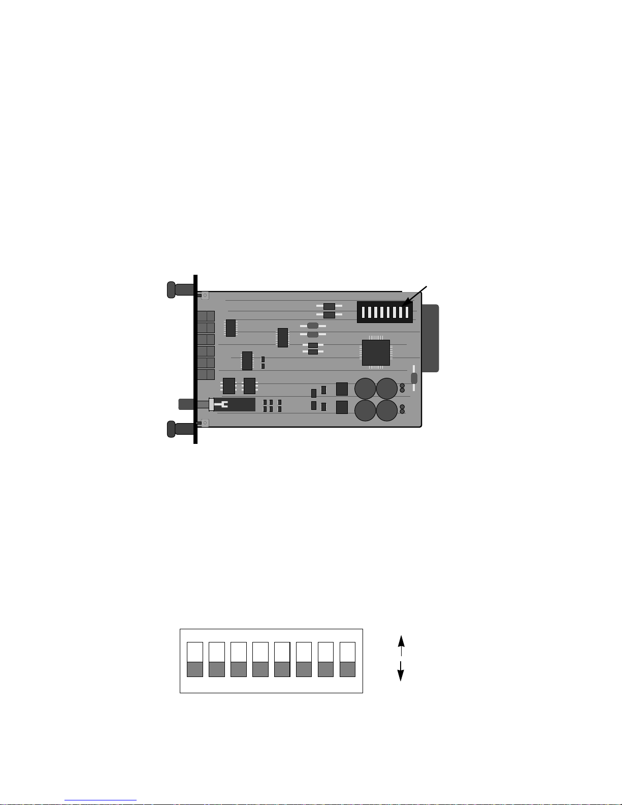
The eight DIP switches on the Model 1070RC board allow you to
specify data rate, clocking method, RTS/CTS delay, and carrier control
method. Figure 2 (below) shows the orientation of the DIP switches
with respect to "ON" and "OFF" positions. The table on the following
page summarizes the switch settings, including the factory default
settings.
Figure 1. Model 1070RC Board Showing Location of DIP Switches
SW1
(SW1-1 on left)
12345678
ON
OFF
ON
Figure 2. Close Up of DIP Switches Showing ON/OFF Positions.
Page 6

Page 7

6
Transmit Clock
Switch 5 is used to specify the clocking method. The Model
1070RC can provide an internal clock (Pin 15),or receive an external
clock (from Pin 24).
Switch 5
On = Internal
Off = External
RTS/CTS Delay
Switches 6 and 7 are used together to specify RTS/CTS delay.
After request to send (RTS) is raised by the host terminal, the 1070RC
raises CTS after a slight delay in order to give the remote terminal time
to receive an incoming signal. Depending on the type of environment,
either a 0 mS, 8 mS or 53 mS delay can be selected.
Switch 6
Switch 7
On On = 0 mS
On Off = 8 mS
Off Off = 53 mS
Carrier Enable
Switch 8 is used to specify how the carrier signal is raised. In most
point-to-point , full duplex applications, the carrier signal can remain
constantly "high". Important Note: In a multi-point environment, set
the host to "Constant Carrier" and each slave to "Controlled by RTS".
Switch 8
On = Controlled by RTS
Off = Constant Carrier
Page 8

Page 9
8
3.3.1 DB-25/RJ-11 & DB-25/RJ-45 STRAP SETTINGS
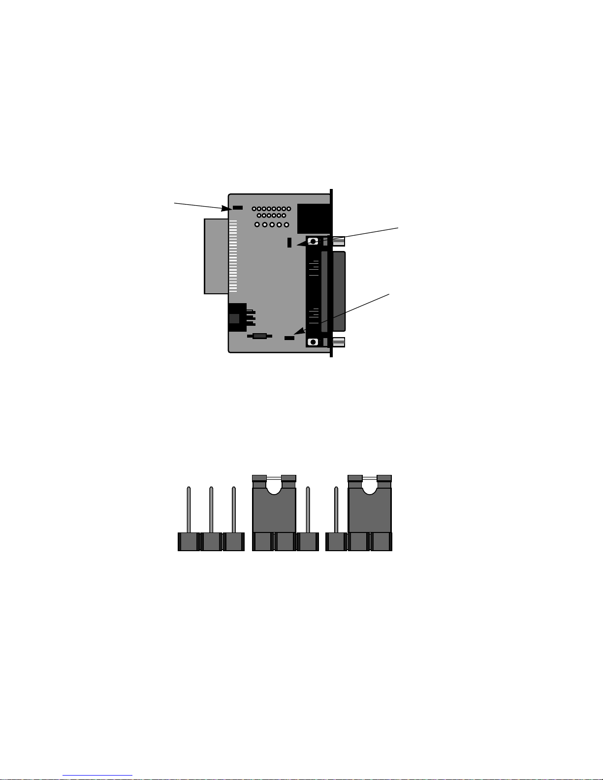
Figure 5 (below) shows strap locations for the Model
1000RCM12511 (DB-25/RJ-11) and the Model 1000RCM12545 (DB25/RJ-45) rear cards. These straps determine various grounding
characteristics for the RS-232 and twisted pair lines.
Figure 6 (below) shows the orientation of the rear interface card
straps. Observe that the strap can either be on pegs 1 and 2, or on
pegs 2 and 3.
Figure 5. DB-25/RJ-11 & DB-25/RJ-45 strap locations
JB2
(peg 1 on left)
JB3
(peg 1 on top)
JB4
(peg 1 on left)
Figure 6. Orientation of interface card straps
123 123 123
Page 10

Page 11

10
3.3.2 RJ-45/RJ-11 & RJ-45/RJ-45 STRAP SETTINGS
Figure 8 (below) shows strap locations for the Model 1000RM1D11
(RJ-45/RJ-11) and the Model 1000RM1D45 (RJ-45/RJ-45) rear cards.
These straps determine various grounding characteristics for the RS232 and twisted pair lines.
The table below provides an overview of strap functions for the
modular/modular cards. Following the table is a detailed description of
each strap's function.
Line Shield & FRGND (JB2)
This strap pertains to the line interface. In the connected (closed)
position, this strap links RJ-11 pins 1 and 6, or RJ-45 pins 2 and 7 to
frame ground. These pins can be used as connections for the twisted
pair cable shield. In the open (disconnected) position, pins 1 and 6 (or
2 and 7) remain connected to each other, but are "lifted" from frame
ground.
JB2
Position 1&2 = Line Shield and FRGND Connected
Position 2&3 = Line Shield and FRGND Not Connected
Figure 8. RJ-45/RJ-11 & RJ-45/RJ-45 strap locations
JB2
(peg 1 on left)
JB6
(peg 1 on top)
JB5
(peg 1 on left)
INTERFACE CARD STRAP SUMMARY TABLE #2
Strap Function Position 1&2 Position 2&3
JB2 Line Shield & FRGND Connected Open*
JB5 SGND & FRGND Connected Open*
JB6 DTE Pin 2 DSR* Not Available
Summary of strap settings, * indicates factory default
Page 12

Page 13

12
4.0 INSTALLATION
This section describes the functions of the Model 1000R16 rack
chassis, tells how to install front and rear Model 1070RC cards into the
chassis, and provides diagrams for wiring up the interface connections
correctly.
4.1 THE MODEL 1000R16 RACK CHASSIS
The 1000R16 Rack Chassis (shown in figure 10, below) has
sixteen short range modem card slots, plus its own power supply.
Measuring only 3.5" high, the 1000R16 is designed to occupy only 2U
in a 19" rack. Sturdy front handles allow the 1000R16 to be extracted
and transported conveniently.
4.1.1 THE RACK POWER SUPPLY
The power supply included in the Model 1000R16 rack uses the
same mid-plane architecture as the modem cards. The front card of
the power supply slides in from the front, and the rear card slides in
from the rear. They plug into one another in the middle of the rack.
The front card is then secured by spring loaded thumb screws and the
rear card by conventional metal screws.
Figure 10. Model 1000R16 Rack Chassis with Power Supply
WARNING! There are no user-serviceable parts in the
power supply section of the Model 1070RC Series.
Voltage setting changes and fuse replacement should only
be performed by qualified service personnel. Contact
Patton Electronics Technical support at (301)975-1007 for
more information.
Page 14

Page 15

14
The Model 1070RC is wired as a DCE (Data Communications
Equipment). Therefore, it wants to connect to a DTE (Data Termination
Equipment). If your RS-232 output device is a DTE, use a
straight
though cable
to connect to the Model 1070RC. If your RS-232 output
device is DCE, call Patton Technical Support at 301-975-1007 for
specific installation instructions.
4.4 TWISTED PAIR CONNECTION
The Model 1070RC operates full duplex over two twisted pair.
In
all
applications, the twisted pair wire must be 26 AWG or thicker,
unconditioned, dry metallic wire. Both shielded and unshielded wire
yield favorable results. Note: The Model 1070RC can only
communicate in a closed data circuit with another Model 1070RC. Dialup analog circuits, such as those used with a standard Hayes-type
modem, are
not acceptable.
For further information about acceptable
wire grades, please refer to the diagrams in Appendix B.
4.4.1 Point-to-Point Twisted Pair Connection
The 6-position RJ-11 and 8-position RJ-45 jack options for the
Model 1070RC (always the
upper
jack on the rear interface card) are
prewired for a standard TELCO wiring environment. Connection of a 4wire twisted pair circuit between two or more Model 1070RCs requires
a
crossed over cable
as shown in the figures below and on the
following page.
RJ-1
1
SIGNAL PIN# COLOR COLOR PIN# SIGNAL
GND 1 Blue..................White 6 GND
RCV-* 2 Yellow...............Red 4 XMT-
XMT+ 3 Green ...............Black 5 RCV+
XMT- 4 Red ..................Yellow 2 RCV-
RCV+ 5 Black ................Green 3 XMT+
GND 6 White................Blue 1 GND
Notice! Any terminal cable connected to the Model
1070RC must be shielded cable, and the outer shield must
be 360 degree bonded–at both ends–to a metal or
metalized backshell.
Page 16

Page 17

5.0 OPERATION
Once you have configured each Model 1070RC and connected the
cables, you are ready to operate the units. Section 5.0 describes the
LED status monitors, the power-up procedure, and the use of the builtin loopback test modes.
5.1 LED STATUS MONITORS
The Model 1070RC features ten front panel status LEDs that
indicate the condition of the modem and communication link. Figure 12
(below) shows the relative front panel positions of the LEDs. Following
figure 12 is a description of each LED's function.
Power glows green when power is applied to the Model
1070RC front card.
TD & RD The green "TD" and "RD" indicators blink to show
positive state data activity. The red "TD" and "RD"
indicators blink to show negative state data activity.
Solid red indicates a connection in an idle state.
Cntrl
in
and glow red to show that either control signal is off.
Cntrl
out
Glow green to show that either control signal is on.
When the 1070RC is connected to a DTE, Control In
will glow green for a positive polarity on Pin 4 (RTS).
Control Out will glow green for an incoming signal
from the line and an outgoing CD signal on RS-232
pin 8.
Test glows green when the loopback test modes are
activated.
Figure 12. The Model 1070RC front panel, showing LED positions
Model 1070RC
Power
TD
RD
Cntrl
Out
Test
Cntrl
In
Page 18

Page 19

18
5.3 TEST MODES
The Model 1070RC offers two diagnostic modes: local analog loop
and remote analog loop. These test modes are activated
simultaneously
by depressing the "Test" button on the front panel of the
Model 1070RC.
Local Analog Loop
The Local Analog Loop test mode causes any data sent to the
local 1070RC by the local RS-232 device to be echoed
back
to that RS232 device. For example, characters typed on the keyboard of a
terminal will appear on the terminal screen. If characters are not
echoed back, check the connection between the local RS-232 device
and the local 1070RC. All 1070RC's in the system should be tested in
this manner
Remote Analog Loop
The Remote Analog Loop test mode causes any characters sent
from the
remote
1070RC to the local 1070RC to be returned back to the
remote
device (see Figure 13). Note: Only the
local
1070RC should
be in "test" mode. The remote 1070RC should be in "normal"
operating mode or this test will not work. If no characters are echoed
back, check the wiring between the two 1070RCs. Be sure to wire the
units according to the instructions in Section 4.0 Installation.
RD
TD
TD
RD
Local 1070RC
In Normal Mode
Remote 1070RC
In Normal Mode
TX+
TX-
RXRX+
RX+
RX-
TXTX+
RD
TD
TD
RD
Local 1070RC
In Loopback Mode
Remote 1070RC
In Normal Mode
RX+
RX-
TXTX+
TX+
TX-
RXRX+
Figure 13. Normal operating mode vs. loopback test mode
Page 20

Page 21

20
APPENDIX B.
MODEL 1070RC CABLE RECOMMENDATIONS
The Patton Model 1070RC operates at frequencies of 20kHz or less
and has been performance tested by Patton technicians using twistedpair cable with the following characteristics:
W
ire Gauge Capacitance Resistance
19 AWG/.9mm 83nf/mi or 15.72 pf/ft. .0163 Ohms/ft.
22 AWG/.6mm 83nf/mi or 15.72 pf/ft. .0326 Ohms/ft.
24 AWG/.5mm 83nf/mi or 15.72 pf/ft. .05165 Ohms/ft.
Using or simulating cable with the above characteristics, the
following data rate/distance results were obtained by Patton during
bench tests:
Data Rate (Bps)
Gauge (AWG) / Distance (Mi)
19 22 24
19,200 2.5 2.1 1.3
9,600 3.7 2.3 1.7
4,800 4.9 4.9 2.5
2,400 8.2 5.8 4.6
1,200 10.0 8.3 6.8
To gain optimum performance from the 1070RC, please keep the
following guidelines in mind:
•
Always
use twisted pair wire--this is not an option.
• Use twisted pair wire with a capacitance of 20pf/ft or less.
• Avoid twisted pair wire thinner than 26 AWG (i.e. avoid higher
AWG numbers than 26)
• Use of twisted pair with a resistance greater than the above
specifications may cause a reduction in maximum distance
obtainable. Functionality should not be affected.
• Environmental factors too numerous to mention can affect the
maximum distances obtainable at a particular site. Use the above
data rate/distance table as a
general guideline only.
Page 22

Page 23

APPENDIX D.
MODEL 1070RC INTERFACE STANDARDS
1- (FG) Frame Ground
2- (TD) Transmit Data To 1070RC
3- (RD) Receive Data From 1070RC
4- (RTS) Request to Send To 1070RC
5- (CTS) Clear to Send From 1070RC
6- (DSR) Data Set Ready From 1070RC
7- (SG) Signal Ground
8- (DCD) Data Carrier Detect From 1070RC
From 1070RC Transmit Clock - 15
From 1070RC Receive Clock - 17
To 1070RC Data Term. Ready (DTR) - 20
To 1070RC External Clock - 24
DIRECTION STANDARD RS-232C/V.24 "DCE" SETTING DIRECTION
EIA/TIA-561 REFERENCE - 8 Wire RJ-45
Contact Number Circuit Description
1 125 Ring Indicator or DSR
2 109 Received Line Signal Indicator
3 108 / 2 DTE Ready
4 102 Signal Common
5 104 Received Data
6 103 Transmitted Data
7 106 Clear to Send
8 105 / 133 Request to Send / Ready for Receiving
PATTON MODIFIED MODULAR INTERFACE - 10 Wire RJ-45
Contact Number Circuit Description
1 N/A Receive Clock
2 125 Ring Indicator or DSR
3 109 Received Line Signal Indicator
4 108 / 2 DTE Ready
5 102 Signal Common
6 104 Received Data
7 103 Transmitted Data
8 106 Clear to Send
9 105 / 133 Request to Send / Ready for Receiving
10 N/A Transmit Clock
Page 24

Page 25

Page 26

Page 27

Page 28

Dear Valued Customer,
Thank you for purchasing Patton Electronics products! We do
appreciate your business. I trust that you find this user manual helpful.
We manufacture one of the widest selections of data
communications products in the world including CSU/DSU's, network
termination units, powered and self-powered short range modems, fiber optic
modems, interface converters, baluns, electronic data switches, data-line surge
protectors, multiplexers, transceivers, hubs, print servers and much more. We
produce these products at our Gaithersburg, MD, USA, facility, and can
custom manufacture products for your unique needs.
We would like to hear from you. Please contact us in any of the
following ways to tell us how you like this product and how we can meet your
product needs today and in the future.
Web: http://www.patton.com
Sales E-mail: sales@patton.com
Support E-mail: support@patton.com
Phone - Sales (301) 975-1000
Phone - Support (301) 975-1007
Fax: (301) 869-9293
Mail: Patton Electronics Company
7622 Rickenbacker Drive
Gaithersburg, MD 20879 USA
We are committed to a quality product at a quality price. Patton
Electronics is ISO 9001 certified. We meet and exceed the highest
standards in the industry (CE, UL, etc.).
It is our business to serve you. If you are not satisfied with any
aspect of this product or the service provided from Patton Electronics or its
distributors, please let us know.
Thank you.
Burton A.Patton
Vice President
P.S. Please tell us where you purchased this product.
_________________________________________________________
_________________________________________________________
_________________________________________________________
_________________________________________________________
_________________________________________________________
_________________________________________________________
_________________________________________________________
 Loading...