

Page 1
USER
MANUAL
MODEL 1070
AC Powered, Synchronous
Short Range Modem
Part #07M1070-C
Doc. #067011U
,
Rev. D
Revised 1/22/08
CERTIFIED
An ISO-9001
Certified Company
SALES OFFICE
(301) 975-1000
TECHNICAL SUPPORT
(301) 975-1007
http://www.patton.com
Page 2

Page 3

1.3 SERVICE
All warranty and non-warranty repairs must be returned freight
prepaid and insured to Patton Electronics. All returns must have a
Return Materials Authorization number on the outside of the shipping
container. This number may be obtained from Patton Electronics
Technical Service at (301) 975-1007, http://www.patton.com, or
support@patton.com.
NOTE: Packages received without an RMA number will not be
accepted.
Patton Electronics' technical staff is also available to answer any
questions that might arise concerning the installation or use of your
Model 1070. Technical Service hours: 8AM to 5PM EST, Monday
through Friday.
2
Page 4

Page 5
3.0 CONFIGURATION
The Model 1070 uses a set of eight external DIP switches that allow
configuration to a wide range of synchronous applications. Because all
eight switches are in one externally accessible DIP package, there is no
need to open the Model 1070's case for configuration. The switches allow
you to control line contention, clocking methods, RTS/CTS delay and data
rates. Figures 1 and 2 (below) and Table 1 (opposite page) summarize
the switch locations, positions and functions.
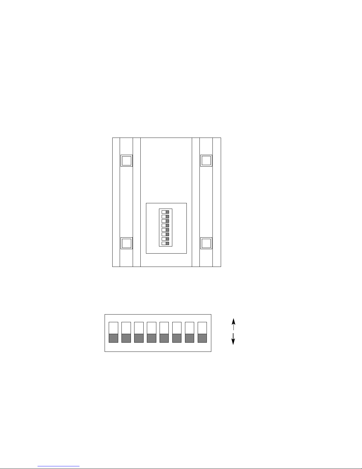
Figure 1. Switch locations underneath Model 1070
Figure 2. Close up of 1070 DIP switch package
showing OFF/ON positions relative to switch numbers
4
12345678
ON
FRONT
REAR
12345678
ON
OFF
ON
Page 6

Page 7

3.1.2 TRANSMIT CLOCK
Switch 5 is used to specify the clocking method. The Model 1070
can provide an internal clock (Pin 15), or receive an external clock
(from Pin 24).
Switch 5
On = External
Off = Internal
3.1.3 RTS/CTS DELAY
Switches 6 and 7 are used together to specify RTS/CTS delay.
After request to send (RTS) is raised by the host terminal, the Model
1070 raises CTS after a slight delay in order to give the remote terminal
time to receive an incoming signal. Depending on the type of
environment, either a 0 mS, 8 mS or 53 mS delay can be selected.
Switch 6
Switch 7
On On = 0 mS
On Off = 8 mS
Off On = 53 mS
3.1.4 CARRIER ENABLE
Switch 8 is used to specify how the carrier signal is raised. In most
point-to-point full duplex applications, the carrier signal can remain
constantly "high". In a multi-point environment, contention for the line is
"controlled" by RTS.
Switch 8
On = Controlled by RTS
Off = Constant Carrier
6
Page 8

Page 9

4.1.2 TWISTED PAIR CONNECTION USING RJ-11
If your two-pair cable is terminated in an RJ-11 plug, you may use
the RJ-11 jack in the back of the Model 1070 to make the connection.
The RJ-11 jack on a Model 1070 series Short Range Modem is
prewired for a standard TELCO wiring environment. To be sure you
have the right wiring, use the diagram below as a guide.
RJ-1
1 SIGNAL
1GND
†
2 RCV
3XMT
4XMT
5 RCV
6GND
For proper signal crossing between two Model 1070s using RJ-11
connectors, pin-out the twisted pair cable according to the diagram
below. The Model 1070 is not sensitive to polarity, so other
configurations may work.
SIGNAL
PIN# COLOR
‡
COLOR PIN# SIGNAL
GND
†
1 Blue White 6 GND
RCV 2 Yellow Red 4 XMT
XMT 3 Green Black 5 RCV
XMT 4 Red Yellow 2 RCV
RCV 5 Black Green 3 XMT
GND 6 White Blue 1 GND
†
Connection to ground is optional
‡
Standard color codes—yours may be different
AT&T standard modular color codes
8
1 - Blue
2 - Yellow
3 - Green
4 - Red
5 - Black
6 - White
Page 10

Page 11

4.2.2 STAR TOPOLOGY
In a star topology, you may connect several Model 1070s together
in a master/slave arrangement. Maximum distance between the units
will vary based upon the number of drops, data rate, wire gauge, etc.
Call Patton Technical Support for specific distance estimates.
Figure 5 (below) shows how to wire the two-pair cables properly for
a Model 1070 star topology. Note that the ground connection is not
needed.
In a multipoint topology, you must configure the CARRIER
ENABLE switch (DIP switch 8) differently for the master Model 1070
than for the slave Model 1070(s). Here are the proper DIP switch
settings for a star topology:
Switch
Number 8
Master Positions OFF
Slave Positions ON
4.2 RS-232 CONNECTION
To connect the Model 1070 to data terminal hardware (PC, host,
terminal, etc.), use a
straight through
RS-232 cable. To connect the
Model 1070 to data communications hardware (modem, multiplexer,
etc.), use a
null modem
RS-232 cable.
HOST FIRST SLAVE SECOND SLAVE
XMT RCV
RCV
XMT RCV
RCV
RCV XMT
XMT
RCV XMT
XMT
Figure 5. Model 1070 star wiring
10
Page 12

Page 13

5.2.2 REMOTE ANALOG LOOP
The second test mode is Remote Analog Loop. To enter this
mode, set one of the Model 1070s (local) in test mode by depressing
the "Loopback Test" switch. Any characters sent from the remote
Model 1070 will be returned back to the originating device (see Figure
6). If no characters are echoed back, check the wiring between the two
Model 1070s. Be sure to wire the units according to the instructions in
Section 4.0 Installation.
Figure 6. Loopback Test Modes
RD
TD
TD
RD
Local 1070RC
In Normal Mode
Remote 1070RC
In Normal Mode
TX+
TX-
RX-
RX+
RX+
RX-
TX-
TX+
RD
TD
TD
RD
Local 1070RC
In Loopback Mode
Remote 1070RC
In Normal Mode
RX+
RX-
TX-
TX+
TX+
TX-
RX-
RX+
12
Local 1070
In Normal Mode
Remote 1070
In Normal Mode
Remote 1070
In Normal Mode
Local 1070
In Loopback Mode
Page 14

Page 15

14
APPENDIX B
PATTON MODEL 1070 CABLE RECOMMENDATIONS
The Patton Model 1070 is designed and tested to communicate
over twisted-pair cable with the following characteristics:
W
ire Gauge Capacitance Resistance
19 AWG/.9mm 83nF/mi or 15.72 pF/ft. .0163Ω/ft.
22 AWG/.6mm 83nF/mi or 15.72 pF/ft. .0326Ω/ft.
24 AWG/.4mm 83nF/mi or 15.72 pF/ft. .05165Ω/ft.
Using the above characteristics as a baseline, we estimate the
distance limitations for the Model 1070 to be as follows.
To reduce the potential of difficulties in the field, we recommend that
the cable used to connect the Model 1070s have a capacitance of no
greater than 20pF/ft., and that the wire be no thinner than 26 AWG.
The Model 1070 is designed to withstand normal environmental noise
and conditions. However, other environmental factors too numerous to
discuss may affect proper operation.
The distance table above should
be used as a general guideline only.
Data
Rate
19,200 2.5 (4.0) 2.1 (3.4) 1.3 (2.1)
9,600 3.7 (6.0) 2.3 (3.7) 1.7 (2.7)
4,800 4.9 (7.9) 4.9 (7.9) 2.5 (4.0)
2,400 8.2 (13.2) 5.8 (9.3) 4.6 (7.4)
1,200 10.2 (16.4) 8.3 (13.4) 6.8 (10.9)
Model 1070 Distance Table - Miles (Km)
Wire Gauge
19 (.9mm) 22 (.6mm) 24 (.4mm)
Page 16

Page 17

APPENDIX D
PATTON MODEL 1070 BLOCK DIAGRAM
16
Page 18

Page 19

APPENDIX B
TROUBLESHOOTING
SYMPTOM PROBLEM SOLUTION
"TD" and "RD" LEDs
indicate activity, but
units will not
communicate or
data is garbled
"TD" and "RD" LEDs
indicate activity, but
"CD" LED is unlit or
red (should be
green)
Occasional data
errors
1. Improper RS-232
wiring
2. Improper twisted
pair wiring
3. Improper bit rate
setting
1. Defective twisted
pair line
2. Poor twisted pair
connection to Model
1070s
1. Distance/bit rate
capacity exceeded
2. Poor quality twisted
pair circuit
3. Poor twisted pair
connections to Model
1070s
1. Check wiring
between Model 1070
and connected DTE
device—it should be
straight through
2. Compare your
twisted pair wiring with
the diagram in Section
4.1
3. Make sure the bit
rates on all connected
serial devices are the
same
1. Test continuity of
twisted pair line
2. Check screw
terminal/RJ-11
connections to Model
1070s; check integrity
of plug RJ-11
terminations
1. Check specifications
in Appendix A
2. Use a different
twisted pair circuit
3. Check screw
terminal/RJ-11
connections to Model
1070s; check integrity
of plug RJ-11
terminations
18
Page 20

 Loading...