

Page 1

USER
MANUAL
MODEL 1015 and
1015S
DB-15 Async
Short Range Modem
SALES OFFICE
(301) 975-1000
TECHNICAL SUPPORT
(301) 975-1007
http://www.patton.com
Part# 07M1015-B
Doc# 024011UB
Revised 5/24/94
Page 2

1.0 WARRANTY INFORMATION
Patton Electronics warrants all Model 1015 components to be
free from defects, and will—at our option—repair or replace the product should it fail within one year from the first date of shipment.
This warranty is limited to defects in workmanship or materials,
and does not cover customer damage, abuse or unauthorized modification. If this product fails or does not perform as warranted, your sole
recourse shall be repair or replacement as described above. Under no
condition shall Patton Electronics be liable for any damages incurred
by the use of this product. These damages include, but are not limited
to, the following: lost profits, lost savings and incidental or consequential damages arising from the use of or inability to use this product.
Patton Electronics specifically disclaims all other warranties,
expressed or implied, and the installation or use of this product shall
be deemed an acceptance of these terms by the user.
1.1 RADIO AND TV INTERFERENCE
The Model 1015 generates and uses radio frequency energy, and
if not installed and used properly—that is, in strict accordance with the
manufacturer’s instructions—may cause interference to radio and television reception. The Model 1015 has been tested and found to comply with the limits for a Class A computing device in accordance with
the specifications in Subpart J of Part 15 of FCC rules, which are
designed to provide reasonable protection from such interference in a
commercial installation. However, there is no guarantee that interference will not occur in a particular installation. If the Model 1015 does
cause interference to radio or television reception, which can be determined by turning the power off or disconnecting the modem, the user is
encouraged to try to correct the interference by one or more of the following measures: moving the computing equipment away from the
receiver, re-orienting the receiving antenna and/or plugging the receiving equipment into a different AC outlet (such that the computing
equipment and receiver are on different branches).
1.2 SERVICE
All warranty and non-warranty repairs must be returned freight
prepaid and insured to Patton Electronics. All returns must have a
Return Materials Authorization number on the outside of the shipping
container. This number may be obtained from Patton Electronics
Technical Service at (301) 975-1007.
Packages received without an
RMA number will not be accepted.
Patton Electronics’ technical staff is also available to answer any
questions that might arise concerning the installation or use of your
Model 1015. Technical Service hours: 8AM to 5PM EST, Monday
through Friday.
1
2.0 GENERAL INFORMATION
Thank you for your purchase of this Patton Electronics product.
This product has been thoroughly inspected and tested and is warranted for One Year parts and labor. If any questions or problems arise
during installation or use of this product, please do not hesitate to contact Patton Electronics Technical Support at (301) 975-1007.
2.1 FEATURES
• Direct connection to Unisys 5000/NCR Tower Series processors
• Very thin case for closely spaced computer ports
• Available with RJ-11, RJ-45 or terminal block with strain relief
• External DCE/DTE switch
• Range to 17 miles
• Data rates to 19,200 bps
• No AC power or batteries required
• Surge protection (Model 1015S)
• Made in the USA
2.2 DESCRIPTION
The Patton Model 1015 Miniature Short Range Modem provides
direct connection to DB-15 equipped RS-232 devices, such as the
Unisys (Sperry) 5000 and the NCR Tower series. Using the latest in
surface mount technology, the Model 1015 combines high quality performance and a miniature package. The Model 1015 requires no AC
power or batteries, supports distances to 17 miles and operates at data
rates to 19.2 Kbps. The Model 1015 is compatible with the Model
1000, 1005, 1006, 1009 and other Patton short range modems.
Measuring only 2.6” x 1.3” x .75”, the Model 1015 is housed in a
pop-open ABS plastic case. It is equipped with a male or female DB15 connector and a choice of interfaces (RJ-11 jack, RJ-45 jack or terminal blocks with strain relief). In some models, an externally accessible DCE/DTE switch allows easy connection to multiplexers and other
devices. The surge protected Model 1015S incorporates Silicon
Avalanche Diodes, which provide 600 watts peak per wire of protection
against harmful transient surges.
2
Page 3
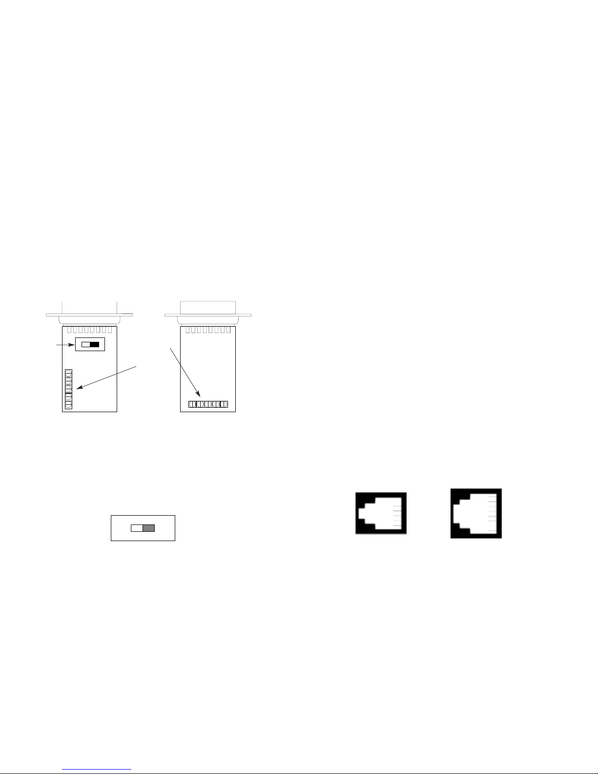
3.0 CONFIGURATION
The Model 1015 is designed to be easy to use. There are no
internal jumpers or configuration switches to set, so there is no need to
open the case to configure the unit (you may need to open the case for
wire connection—refer to section 4.0). However, in some models, you
may have to set the external DCE/DTE switch.
The figure below shows both versions of the Model 1015. If your
model looks like Figure 1, follow the instructions in Section 3.1. If your
Model 1015 looks like Figure 2, your unit will always operate in DCE
mode. Follow the instructions in Section 4.0.
3.1 SETTING THE DCE/DTE SWITCH
If your Model 1015 looks like Figure 1, it comes equipped with an
external DCE/DTE switch and requires special attention. If the device
connected to the Model 1015 is a modem or multiplexer (or is wired
like one), move the switch to “DTE”. This causes the Model 1015 to
behave like Data Terminal Equipment and transmit data on pin 1.
If the device connected to the Model 1015 is a PC, terminal or
host computer (or is wired like one), move the switch to “DCE”. This
setting causes the Model 1015 to behave like Data Communications
Equipment and transmit data on pin 9.
4.0 INSTALLATION
Once you have properly configured the DCE/DTE switch, you are
ready to connect the Model 1015 to your system. This section tells
you how to properly connect the Model 1015 to the twisted pair and
RS-232 interfaces, and how to operate the Model 1015.
4.1 CONNECTION TO THE TWISTED PAIR INTERFACE
The Model 1015 supports data-only communication between two
RS-232 devices at distances to 17 miles and data rates to 19.2 Kbps.
There are two essential requirements for installing the Model 1015:
1. These units work in pairs. Therefore, you must have one Model
1015 at each end of a two twisted pair interface.
2. To function properly, the Model 1015 needs two twisted pairs of
metallic wire. The pairs must be unconditioned, dry metallic wire,
between 19 and 26 AWG (the higher number gauges may limit
distance). Standard dial-up telephone circuits, or leased circuits
that run through signal equalization equipment are not acceptable.
For your convenience, the Model 1015 is available with three dif-
ferent twisted pair interfaces: RJ-11 jack, RJ-45 jack and terminal
blocks with strain relief.
4.1.1 TWISTED PAIR CONNECTION USING RJ-11 OR RJ-45
The RJ-11 and RJ-45 connectors on the Model 1015’s twisted pair
interface are pre-wired for a standard TELCO wiring environment (see
Figure 3). The table on the following page shows the signal/pin relationships:
3 4
DCE/DTE
Switch
Terminal
Block
Terminal
Block
DCE DTE
1 - Blue
2 - Orange
3 - Black
4 - Red
5 - Green
6 - Yellow
7 - Brown
8 - Slate
1 - Blue
2 - Yellow
3 - Green
4 - Red
5 - Black
6 - White
Figure 3. AT&T standard modular color codes
Figure 2Figure 1
Page 4

1. Open the unit by gently inserting a screwdriver between the
DB-15 connector and the lip of the plastic case (see below). You don’t
have to worry about breaking the plastic, but be careful not to bend the
D-sub connector.
Once the unit has been opened, you will be able to see the termi-
nal blocks located at the rear of the PC board.
2. Strip the outer insulation from the twisted pairs about one inch
from the end.
3. Strip the insulation on each of the twisted pair wires about .25”.
RJ-11 SIGNAL RJ-45 SIGNAL
1----------------GND
†
1----------------N/C
2----------------RCV- 2----------------GND
†
3----------------XMT+ 3----------------RCV4----------------XMT- 4----------------XMT+
5----------------RCV+ 5----------------XMT6----------------GND
†
6----------------RCV+
7----------------GND
†
8----------------N/C
When connecting two Model 1015s, it is necessary to use a
“cross-over” cable. The diagram below shows how a crossover cable
should be constructed for an environment where both Model 1015s use
a 4-wire RJ-11 connector. Similar logic should be followed when
using RJ-45 connectors or a combination of the two.
SIGNAL
PIN# COLOR
‡
COLOR PIN# SIGNAL
GND†1 Blue --------------------White 6 GND
†
RCV- 2 Yellow------------------Red 4 XMT-
XMT+ 3 Green ------------------Black 5 RCV+
XMT- 4 Red---------------------Yellow 2 RCV-
RCV+ 5 Black -------------------Green 3 XMT+
GND†6 White-------------------Blue 1 GND
†
†
Connection to ground is optional
‡
Standard color codes—yours may be different
4.1.2 TWISTED PAIR CONNECTION USING TERMINAL BLOCKS
If your RS-232 application requires you to connect two pairs of
bare wires to the Model 1015, you will need to open the case to access
the terminal blocks. The following instructions will tell you how to open
the case, connect the bare wires to the terminal blocks, and fasten the
strain relief collar in place so that the wires won’t pull loose.
5 6
Page 5

4. Connect
one pair
of wires to XMT+ and XMT- (transmit positive
and negative) on the terminal block, making careful note of which color
is positive, and which color is negative.
5. Connect the
other pair
of wires to RCV+ and RCV- (receive
positive and negative) on the terminal block, again making careful note
of which color is positive and which color is negative.
Ultimately, you will want to construct a two pair crossover cable
that makes a connection with the RS-232 device as shown below:
6. If there is a shield around the telephone cable, it may be connected to “G” on the terminal block. To avoid ground loops, we recommend connecting the shield at the computer end only. A ground wire is
not necessary
for proper operation of the Model 1015.
7. When you finish connecting the wires to the terminal block, the
assembly should resemble the diagram below:
8. Place the 2 halves of the strain relief assembly on either side
of the telephone wire and press together very lightly. Slide the assembly so that it is about 2 inches from the terminal posts and press
together firmly. If your cable diameter is too small or too large for our
strain relief, please contact our technical support. We have strain relief
assemblies to accommodate most cable diameters.
9. Insert the strain relief assembly with the wire going through it
into the slot in the bottom half of the modem case and set it into the
recess in the case.
87
+XMT- G -RCV+
+XMT- G -RCV+
XMT + RCV+
XMT - RCV GG
RCV - XMT RCV + XMT +
To Shield (Optional)
}
One Pair
}
One Pair
Page 6

10. TIP the top half of the case as necessary to place it over the
strain relief assembly. Do not snap the case together yet.
11. Insert one captive screw through a saddle washer and then
insert the entire piece through the hole in the DB-15 end of the case.
Snap that side of the case closed. Repeat the process for the other
side. This completes cable installation.
4.2 CONNECTION TO THE RS-232 INTERFACE
Once you have configured the Model 1015 for DTE or DCE and
connected the twisted pair wires correctly, simply plug the 1015 directly
into the DB-15 port of the RS-232 device. After doing so, remember to
insert and tighten the two captive connector screws.
Note: If you must use a cable to connect the Model 1015 to the
RS-232, make sure it is a
straight through
cable of the shortest possible length—we recommend 6 feet or less. The Model 1015 requires a
cable that incorporates pins 1, 2, 3, 4, 9, 10, 11 and 12.
4.3 OPERATING THE MODEL 1015
Once the Model 1015 is properly installed, it should operate transparently—as if it were a standard cable connection. Operating power
is derived from the RS-232 data and control signals; there is no
“ON/OFF” switch. All data signals from the RS-232 interface are
passed straight through. All control signals from the RS-232 interface
are looped back.
Note: If your system requires
hardware
flow control, you will need
the Patton Model 1012 or Model 1060 Short Range Modem. Call
Patton Customer Service at (301) 975-1007 for more information.
APPENDIX A
PATTON MOCEL 1015 SPECIFICATIONS
Transmission Format: Asynchronous
Data Rate: 0 to 19,200 bps (no strapping)
Surge Protection: 600W peak power dissipation at 1 mS
(10 x 1000 µs exponential waveform) and
response time of 1.0 pS
Control Signal: CTS (Pin 10) turns ON immediately after
the terminal raises RTS (Pin 2); DSR (Pin 3)
turns on when powered up; DCD (Pin 12)
turns on immediately after the terminal
raises DTR (Pin 4)
Transmit Line: 4 wire, unconditioned line (2 twisted pairs)
Transmit Mode: Full duplex, 4-wire
Transmit Level: 0 dBm
Line Connection: RJ-11 or RJ-45 jack or 5 screw terminal
posts (4 wires and 1 ground) and a strain
relief insert
Power Supply: No external power required, uses ultra low
power from EIA data and control signals
Size: 2.6” x 1.3” x 0.75”
9 10
Page 7

APPENDIX B
BLOCK DIAGRAM
11
 Loading...