

Page 1
USER
MANUAL
MODEL 1012B
Asynchronous
Carrier Controlled Short
Range Modem
SALES OFFICE
(301) 975-1000
TECHNICAL SUPPORT
(301) 975-1007
http://www.patton.com
Part# 07M1012B
Doc# 040061U,
Rev. B
Revised 1/22/08
An ISO-9001
Certified Company
Page 2

Page 3

2.0 GENERAL INFORMATION
Thank you or buying the Patton Model 1012B. This product has
been thoroughly inspected and tested and is warranted for One Year
parts and labor. Contact Patton Electronics Technical Support if you
have any questions.
2.1 FEATURES
• Supports up to 10 multi-point terminals
• Full or half duplex, point-to-point or multipoint
• Supports hardware handshaking
• External DCE/DTE switch
• Automatic equalization and gain control
• Transformer isolation
• No AC power required
• Supports data rates to 38,400 bps, distances to 6 miles
• Silicon Avalanche Diode surge protection
• Twisted pair connection via RJ-11, RJ-45, or terminal blocks (for
daisy chaining)
• Made in the U.S.A
2.2 DESCRIPTION
In a multi-point environment, the master transmits data to all of the
addressable slave devices (there can be up to 10 slave devices).
Typically the modem at the master site is set for
constant carrier
,
whereas the modems at the slave sites must be configured for
controlled carrier
. Automatic equalization and gain control ensure the
optimal performance for a specific environment. Environments vary in
the twisted-pair wire gauge, quality of the twisted-pair, the data rate,
length of the transmission line, number of slave devices on the circuit,
etc. The transformers eliminate problems caused by ground loops. With
all these features, the 1012B can be used in numerous types of
applications. Some of them are simple point-to-point between buildings,
multipoint applications, and point-to-point applications which require
passing a control signal from end-to-end.
The 1012B uses silicon avalanche diodes (SADs) for protection
against transients. With SADs, the clamping response is superior and
does not degrade in performance after transient “hits.” The
surge/transient protection protects the 1012B as well as the port to
which it is connected.
2
Page 4

Page 5
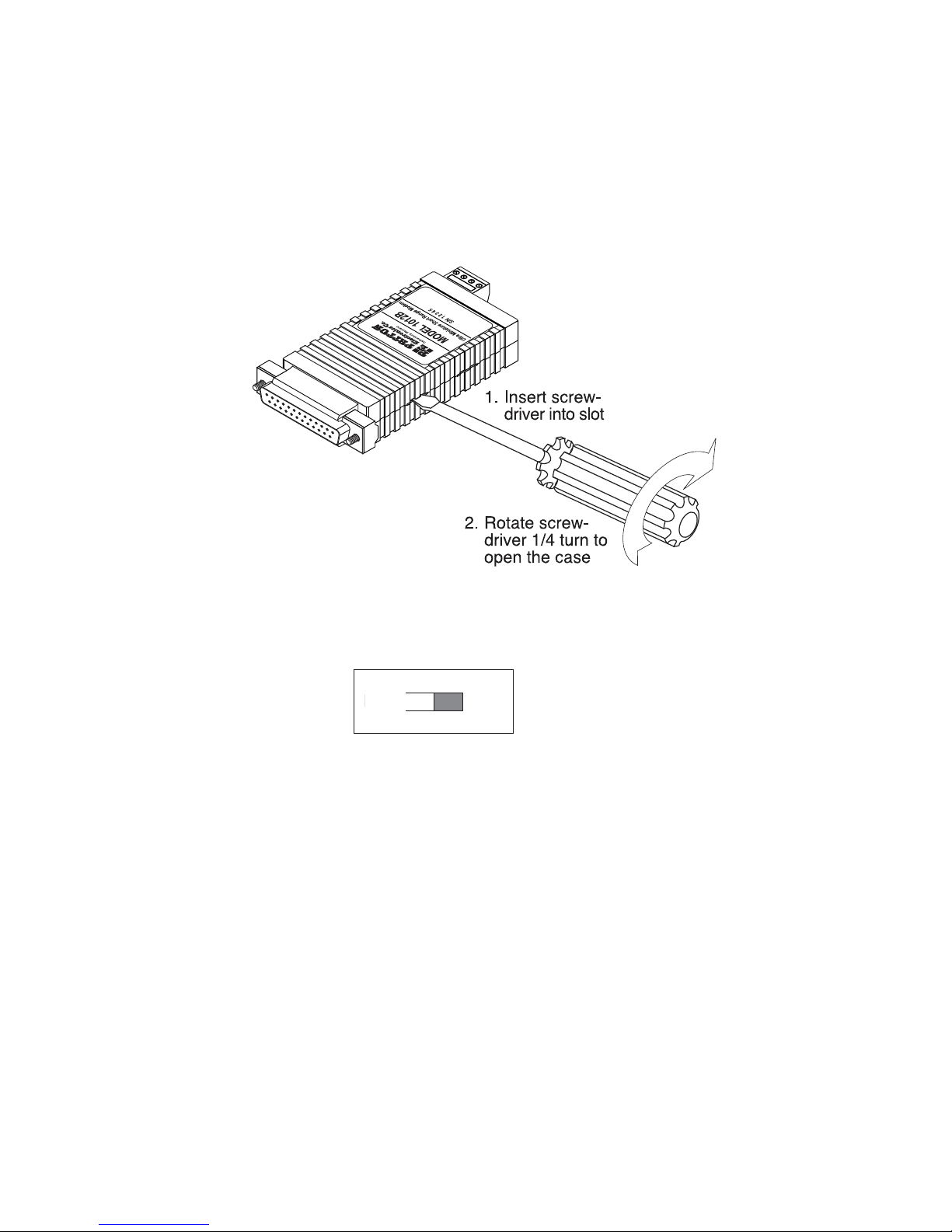
To change the DTE/DCE setting, do the following:
1. Using a small screwdriver, insert the tip into one of the slots in
the side of the Model 1012B (see Figure 2).
2. Rotate the screwdriver as shown in Figure 2 to open the case.
3. If the device connected to the Model 1012B is a PC, terminal
or host computer (or is wired like one), set switch SW1 to “DCE” (see
Figure 3). This causes the Model 1012B to behave like data
communications equipment.
4. If the device connected to the Model 1012B is a modem or
multiplexer (or is wired like one), set the switch to “DTE.” This setting
causes the Model 1012B to behave like data terminal equipment.
5. After you finish configuring the DTE/DCE switch, snap the
case halves back together, then go to section 4.0, “Installation.”
Figure 2. Using a small screwdriver to open the Model 1012B case
4
Figure 3. SW1 DTE/DCE switch
DCE
DTE
Page 6

Page 7

4.0 INSTALLATION
Once you have properly configured the Model 1012B, you are
ready to connect it to your system. This section tells you how to
connect the Model 1012B to the twisted pair and RS-232 interfaces,
and how to operate the Model 1012B.
4.1 HOW TO CONNECT TO THE TWISTED PAIR INTERFACE
The Model 1012B passes data and handshaking signals between
two RS-232 devices at distances to 6 miles (9.7 km) and data rates to
38.4 kbps. There are two requirements for installing the Model 1012B.
1. These units work in pairs. Therefore, you must have one Model
1012B at each end of a two twisted pair interfaces.
2. To function properly, the Model 1012B needs two twisted pair of
metallic wire. They must be unconditioned, dry metallic wire,
unloaded, between AWG 19 and 26 (the higher number gauges
may limit distance somewhat). Standard dial-up telephone
circuits, or leased circuits that run through signal equalization
equipment, are not acceptable.
For your convenience, the Model 1012B is available with the
following twisted pair interfaces: RJ-11 jack, RJ-45 jack, and terminal
blocks.
4.1.1 TERMINAL BLOCK TWISTED PAIR CONNECTION
If your application requires you to connect one or two pair of bare
wires to the Model 1012B, you will need to access the external terminal
blocks. The following instructions will tell you how to connect the bare
wires to the terminal blocks.
1. Strip the outer insulation from the twisted pairs about one inch
from the end.
2. Strip the insulation on each of the twisted pair wires about
0.25 inch.
6
Figure 4. Stripping the outer insulation from the twisted pairs
Page 8

Page 9

Signal/Pin Assignments
The 6-wire RJ-11 and 8-wire RJ-45 jack options for the Model
1012B are prewired for a standard TELCO wiring environment. Use the
guide below when ordering or constructing twisted pair cables.
RJ-11 SIGNAL RJ-45 SIGNAL
1 . . . . . .GND† 1 . . . . . . .N/C
2 . . . . . .RCV- 2 . . . . . .GND†
3 . . . . . .XMT+ 3 . . . . . . .RCV-
4 . . . . . .XMT- 4 . . . . . .XMT+
5 . . . . . .RCV+ 5 . . . . . . .XMT-
6 . . . . . .GND† 6 . . . . . .RCV+
7 . . . . . .GND†
8 . . . . . . .N/C
†
Connection to ground is optional
Crossover Cable Construction
Connection of a 4-wire twisted pair circuit between two or more
Model 1012Bs requires a crossover cable as shown in the figures on
the following page.
RJ-11
SIGNAL PIN# PIN# . . . . . . . . . . .SIGNAL
GND† 1 6 . . . . . . . . . . . . .GND†
RCV- 2 4 . . . . . . . . . . . . . .XMT-
XMT+ 3 5 . . . . . . . . . . . . .RCV+
XMT- 4 2 . . . . . . . . . . . . . .RCV-
RCV+ 5 3 . . . . . . . . . . . . .XMT+
GND† 6 1 . . . . . . . . . . . . .GND†
RJ-45
SIGNAL PIN# PIN# . . . . . . . . . . .SIGNAL
GND† 2 7 . . . . . . . . . . . . .GND†
RCV- 3 5 . . . . . . . . . . . . . .XMT-
XMT+ 4 6 . . . . . . . . . . . . .RCV+
XMT- 5 3 . . . . . . . . . . . . . .RCV-
RCV+ 6 4 . . . . . . . . . . . . .XMT+
GND† 7 2 . . . . . . . . . . . . .GND†
†
Connection to ground is optional
8
Page 10

Page 11

4.2.2 DAISY CHAIN TOPOLOGY
Using a daisy chain topology, you may connect several Model
1012Bs together in a master/slave arrangement. Maximum distance
between the units will vary based upon the number of drops, data rate,
wire gauge, etc. Contact Patton Technical Support at (301) 975-1007;
http://www.patton.com; or, support@patton.com for specific
distance estimates.
Figure 6 shows how to wire the two-pair cables properly for a
Model 1012B’s daisy chain topology. Note that the ground connection is
not needed.
Optional Connection: Dual Modular Jacks
To facilitate daisy chaining, the Model 1012B is available in a
"DRJ11" (dual RJ-11) or "DRJ45" (dual RJ-45) version. These units have
two specially wired modular jacks for twisted pair connection. With the
dual modular units, you do not need to build cumbersome "Y" cables for
your daisy chain application. Simply use a crossover cable to go between
the host and the first slave (see Section 4.1.2 for crossover cable wiring
instructions), and straight through cables between the slaves.
4.3 CONNECTION TO THE RS-232 INTERFACE
Once you have properly configured the Model 1012B and
connected the twisted pair wires correctly, plug the Model 1012B
directly into the DB-25 port of the RS-232 device. After doing so,
remember to insert and tighten the two captive connector screws.
Note: If you must use a cable to connect the Model 1012B to the
RS-232 device, make sure it is a straight through cable of
the shortest possible length—we recommend 6 feet (1.8
meters) or less.
4.4 OPERATING THE MODEL 1012B
Once the Model 1012B is properly installed, it should operate
transparently—as if it were a standard cable connection. Operating power
is derived from the RS-232 data and control signals; there is no "ON/OFF"
switch. All data signals from the RS-232 interface are passed straight
through. Additionally, one control signal is passed in each direction.
10
HOST FIRST SLAVE OTHER SLAVE(S)
XMT+ RCV+ RCV+
XMT- RCV- RCVRCV+ XMT+ XMT+
RCV- XMT- XMT-
Table 3. Daisy Chain Wiring for Model 1012B Host and Slaves
Page 12

Page 13

APPENDIX B
RS-232C PIN CONFIGURATIONS
12
1- (FG) Frame Ground
2- (TD) Transmit Data To Model 1012B
3- (RD) Receive Data From Model 1012B
4- (RTS) Request to Send To Model 1012B
5- (CTS) Clear to Send From Model 1012B
6- (DSR) Data Set Ready From Model 1012B
7- (SG) Signal Ground
8- (CD) Carrier Detect From Model 1012B
9- External Power To Model 1012B
To Model 1012B Data Term. Ready (DTR) - 20
DIRECTION "DCE" STANDARD SETTING DIRECTION
1- (FG) Frame Ground
2- (TD) Transmit Data From Model 1012B
3- (RD) Receive Data To Model 1012B
4- (RTS) Request to Send From Model 1012B
5- (CTS) Clear to Send To Model 1012B
6- (DSR) Data Set Ready To Model 1012B
7- (SG) Signal Ground
8- (CD) Carrier Detect To Model 1012B
9- External Power To Model 1012B
From Model 1012B Data Term. Ready (DTR) - 20
DIRECTION "DTE" STANDARD SETTING DIRECTION
Page 14

Page 15

Notes
________________________________________________________
________________________________________________________
________________________________________________________
________________________________________________________
________________________________________________________
________________________________________________________
________________________________________________________
________________________________________________________
________________________________________________________
________________________________________________________
________________________________________________________
________________________________________________________
________________________________________________________
________________________________________________________
________________________________________________________
________________________________________________________
________________________________________________________
________________________________________________________
________________________________________________________
________________________________________________________
________________________________________________________
________________________________________________________
________________________________________________________
Page 16

 Loading...