

Page 1
Copyright statement
Copyright © 2012, Patton Electronics Company. All rights reserved.
The information in this document is subject to change without notice. Patton Electronics assumes no
liability for errors that may appear in this document.
Trademarks statement
The term BODi rS is a trademark of Patton Electronics Company. All other trademarks presented in this document
are the property of their respective owners.
Warranty, Trademark, & Compliance Information
For warranty, trademark and compliance information, refer to the user manual for your BODi rS model, avail-
able online at www.patton.com/manuals.
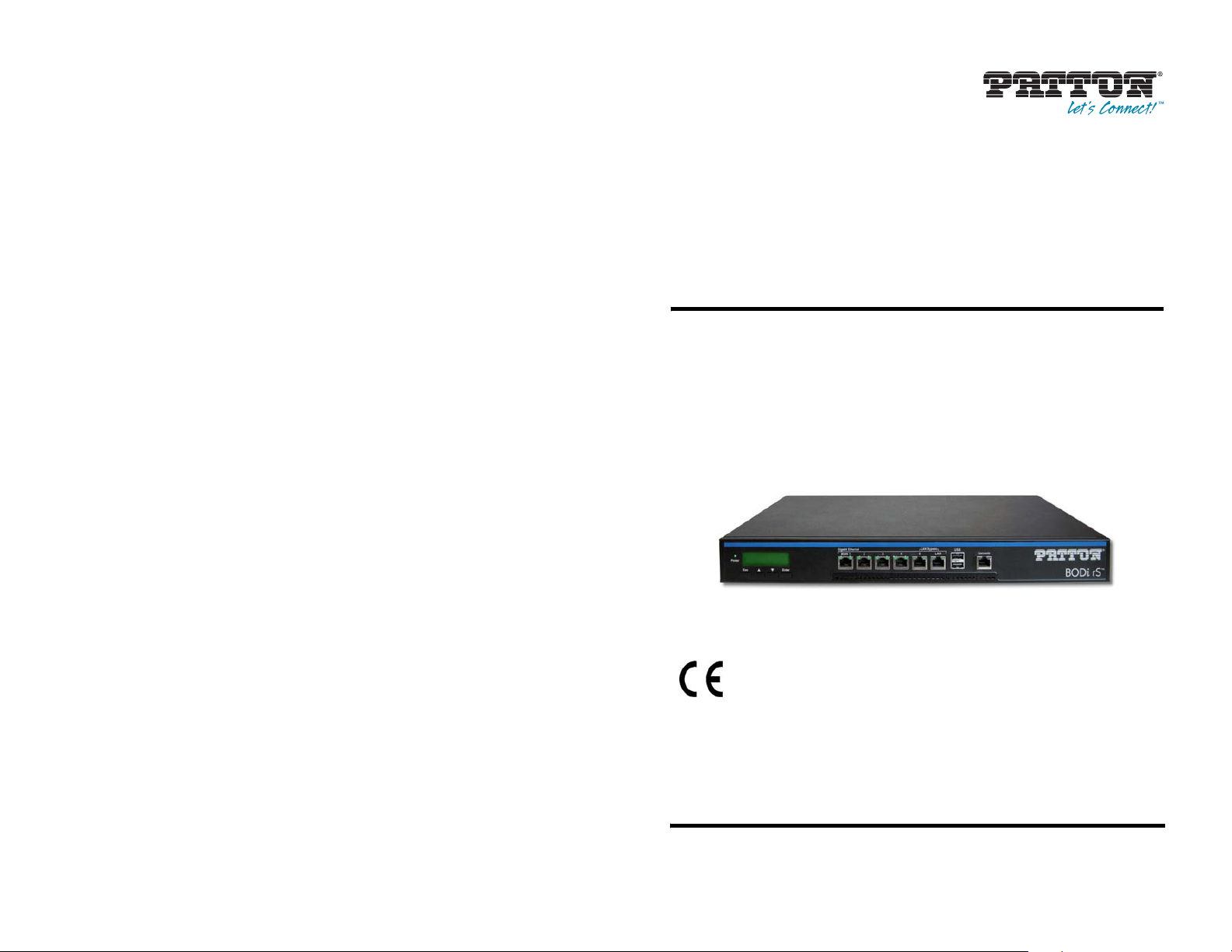
BODi rS BD1000 Series
Bandwidth-on-Demand Internet
Network Appliance
Quick Start Guide
8 BODi rS BD1000 Quick Start Guide
This is a Class A device and is not intended for use in a residential environment.
Part Number: 07MBD1000-QS, Rev. A
Revised: November 28, 2012
Sales Office: +1 (301) 975-1000
Technical Support: +1 (301) 975-1007
E-mail: support@patton.com
WWW: www.patton.com
Page 2
WARNING
• Do not open the device when the power cord is connected. For systems without a power switch and without an external power
adapter, line voltages are present within the device when the power
cord is connected.
• For devices with an external power adapter, the power adapter shall
be a listed Limited Power Source The mains outlet that is utilized to
power the device shall be within 10 feet (3 meters) of the device,
shall be easily accessible, and protected by a circuit breaker in compliance with local regulatory requirements.
• For AC powered devices, ensure that the power cable used meets all
applicable standards for the country in which it is to be installed.
• For AC powered devices which have 3 conductor power plugs (L1, L2
& GND or Hot, Neutral & Safety/Protective Ground), the wall outlet
(or socket) must have an earth ground.
• For DC powered devices, ensure that the interconnecting cables are
rated for proper voltage, current, anticipated temperature, flammability, and mechanical serviceability.
• WAN, LAN & PSTN ports (connections) may have hazardous voltages
present regardless of whether the device is powered ON or OFF.
PSTN relates to interfaces such as telephone lines, FXS, FXO, DSL,
xDSL, T1, E1, ISDN, Voice, etc. These are known as “hazardous network voltages” and to avoid electric shock use caution when working
near these ports. When disconnecting cables for these ports, detach
the far end connection first.
• Do not work on the device or connect or disconnect cables during periods of lightning activity.
B.0 Compliance Information
B.1 Compliance
EMC
•
EN55022, Class A
•
EN55024
Low-Voltage Directive (Safety)
•
IEC/EN60950-1, 2nd edition
B.2 CE Declaration of Conformity
Patton Electronics, Inc declares that this device is in compliance with the essential requirements and other relevant provisions of Directive 2004/108/EC relating to electromagnetic compatibility and Directive 2006/95/EC
relating to electrical equipment designed for use within certain voltage limits. The Declaration of Conformity
may be obtained from Patton Electronics, Inc at www.patton.com/certifications
The safety advice in the documentation accompanying this device shall be obeyed. The conformity to the above
directive is indicated by CE mark on the device.
B.3 Authorized European Representative
D R M Green, European Compliance Services Limited.
Avalon House, Marcham Road, Abingdon,
Oxon OX14 1UD, UK
.
This device contains no user serviceable parts. This device can only be
repaired by qualified service personnel.
WARNING
In accordance with the requirements of council directive 2002/96/EC on Waste of
Electrical and Electronic Equipment (WEEE), ensure that at end-of-life you separate
this product from other waste and scrap and deliver to the WEEE collection system in
your country for recycling.
2 BODi rS BD1000 Quick Start Guide
BODi rS BD1000 Quick Start Guide 7
Page 3

A.0 Customer and Technical Support
Toll-Free VoIP support: call sip:support@patton.com with a VoIP SIP client
Online support: www.patton.com
E-mail support: support@patton.com—answered within 1 business day
Telephone support:
•
Standard: +1 (301) 975-1007 (USA), Monday–Friday: 8:00 am to 5:00 pm EST (1300 to
2200 UTC/GMT)
•
Alternate: +41 (0)31 985 25 55 (Switzerland), Monday–Friday: 9:00 am to 5:30 pm CET (08:00 to 16:30
UTC/GMT)
Fax: +1 (301) 869-9293 (USA) or +41 (0)31 985 25 26 (Switzerland)
Electrostatic Discharge (ESD) can damage equipment and impair electrical
circuitry. It occurs when electronic printed circuit cards are improperly
handled and can result in complete or intermittent failures. Do the follow-
CAUTION
ing to prevent ESD:
• Always follow ESD prevention procedures when removing and replacing cards.
• Wear an ESD-preventive wrist strap, ensuring that it makes good
skin contact. Connect the clip to an unpainted surface of the chassis
frame to safely channel unwanted ESD voltages to ground.
• To properly guard against ESD damage and shocks, the wrist strap
and cord must operate effectively. If no wrist strap is available,
ground yourself by touching the metal part of the chassis.
1.0 Preparing to Install the BODi rS
You will need the following to install your BODi rS:
•
At least one Internet/WAN access account
•
For each network connection, one 10/100Base-T UTP cable with RJ45 connector, or one 1000Base-T Cat5E
UTP cable for the Gigabit port or one USB modem for the USB WAN port
•
A computer with TCP/IP network protocol and a web browser installed. Supported browsers include Microsoft
Internet Explorer 7.0 or above, Mozilla Firefox 3.0 or above, Apple Safari 3.1.1 or above, and Google
Chrome 2.0 or above.
6 BODi rS BD1000 Quick Start Guide
Proceed to Chapter 2.0 Connecting the BODi rS Interfaces on page 4.
BODi rS BD1000 Quick Start Guide 3
Page 4

2.0 Connecting the BODi rS Interfaces
LCD Menu Display
Gigabit Ethernet
W AN 1 LAN
Power
Esc
Enter
2345
LAN Bypass
USB
Console
1. Connect one end of the USB cable to one of the USB ports.
2. If you are installing a 3G/4G failover modem, connect the other end of the cable to the modem. Other-
wise, connect the other end of the cable to a USB 2.0 device.
3. If there is a second cellular modem, connect one end of the USB c able to one of the USB ports, then con-
nect the remaining end to the USB 2.0 device.
Menu Key: Down
Menu Key: Up
Menu Key: Esc
Power LED
Menu Key: Enter
Gigabit Ethernet
Ports WAN 1-5
(RJ-45)
Gigabit Ethernet
Fan
LAN Port
(RJ-45)
Console
3G/4G USB
Power Connector
Power Switch
Figure 1. BODi rS BD1000 interfaces
BODi rS includes the following Ethernet ports:
•
LAN port: Connects to a computer or similar device on the local area network (LAN)
•
WAN ports 1 to 5: Connect to T1, DSL, or cable modems on the wide area network (WAN)
Note WAN port 5 and the LAN port can be connected to TBD to create the LAN Bypass.
2.1 Installing the LAN Interface Cable
1. Connect one RJ45 end of an Ethernet cable to the LAN port (see Figure 1).
2. Connect the other end of the Ethernet cable to the computer.
Fan
3.0 Powering Up the BD1000
1. Insert the female end of the AC power cord into the power connector (see Figure 1 on page 4).
2. Connect the male end of the power cord into an AC power outlet (100–240 VAC).
3. Set the power switch (see Figure 1 on page 4) to | (on).
4.0 Connecting to the Web Admin Interface
After physically connecting to the LAN, use the Web Admin interface to configure the BODi rS interfaces.
Do the following to log in to the Web Admin Interface:
1. Start a web browser on the computer connected to the BODi rS LAN port.
2. Enter the following default LAN IP address in the address field of the web browser: http://192.168.1.1
3. Enter the username admin and password admin to log in to the Web Admin Interface. (You may change
the Admin and Read-only User Password by clicking on System > Admin Security in the Web Admin Interface). After successfully logging in, the Dashboard of the Web Admin Interface displays:
2.2 Connecting the WAN Interface Cables
1. Connect one RJ45 end of an Ethernet cable to WAN port 1 (see Figure 1).
2. Connect the other end of the Ethernet cable to a modem.
3. Repeat steps 1 and 2 to install the remaining Ethernet cables to ports 2 to 5.
2.3 Connecting the USB Interfaces
Do the following to connect USB cables (Standard-A plugs at both ends) between the BODi rS USB 2.0 ports and
the 3G/4G failover modem and a USB 2.0 device, or between BODi ports and two USB 2.0 devices:
4 BODi rS BD1000 Quick Start Guide
Figure 2. Web Admin Interface home page
The Web Admin Interface Dashboard shows the current WAN and LAN settings and statuses. The Dashboard
enables you to change the priority of the WAN connections off or on. For more information about configuring
these connections, refer to Chapter 3 in the BODi rS BD1000 Series User Manual: (www.patton.com/manu-
als/BD1000.pdf).
BODi rS BD1000 Quick Start Guide 5
 Loading...