

Page 1
OnSite Models 9100, 9130, 9200 & 9300
Expansion Modules
Quick Start Guide
Part Number: 07M9000-QS, Rev. B
Revised: February 20, 2012
Sales Office: +1 (301) 975-1000
Technical Support: +1 (301) 975-1007
E-mail: support@patton.com
WWW: www.patton.com
Page 2
Read the safety information in the OnSite Series User Manual and
Administrator’s Reference Guide thoroughly before installing and operat-
ing your OS-10 Series system. Failure to follow this safety information
WARNING
can lead to personal injury or damage to the equipment.
1.0 Introduction
This guide provides instructions for adding expansion modules to your Patton OnSite base system. Refer to the
following sections for installation instructions for your specific module:
•
2.0 “Model 9100 E1 Module” on page 2
•
3.0 “Model 9130 DS3/E3 Module” on page 4
•
4.0 “Model 9200 Ethernet Module” on page 5
•
5.0 “Model 9300 STM-1 Module” on page 6
2.0 Model 9100 E1 Module
2.1 Unpacking and Installation
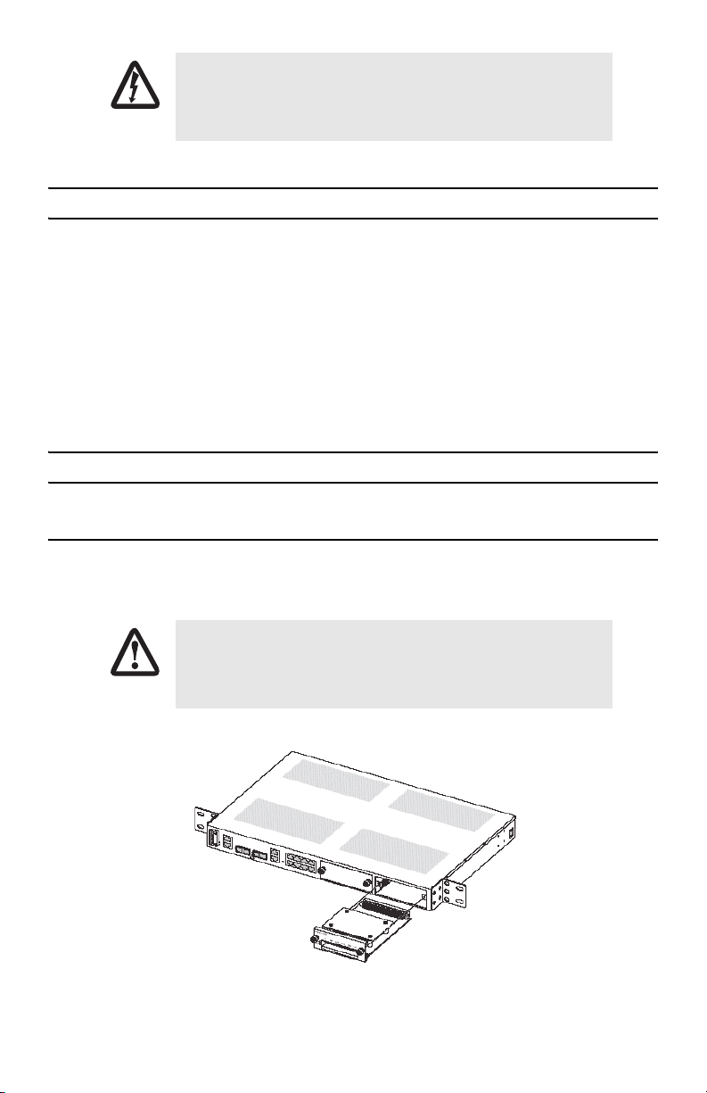
To install the HD-E1 module, follow the procedures in Chapter 7 of the OnSite Series Administrator’s Reference
Guide. Figure 1 shows the alignment and insertion of the HD-E1 module into one of the available expansion
slots of the OS-10.
The High-density E1 module is NOT hot swappable. You will need to
power down the OS-10 system before starting the module insertion procedure.
CAUTION
Figure 1. Installing the HD-E1 module
2 OnSite Expansion Modules Quick Start Guide
Page 3
2.2 Cable Management
The HD-E1 module uses a future bus connector on the front panel and requires the use of cables with compatible
plugs for access to the E1 signals. These cables are ordered separately from the module and need to be specified
according to the termination option for the module (75-ohm or 120-ohm) and the required cable length for the
site.
Note Contact your local Patton sales representative if the shipment does not include the required cables for
the module.
Chapter 7 of the OnSite Series Administrator’s Reference Guide provides information on the location and signal
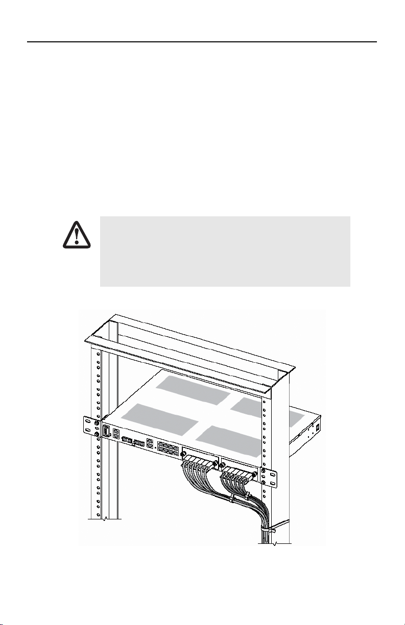
pin-out for each of the 21 E1 ports on the future bus connector. Each module requires six cables for access to all
21 E1 ports. When installing the cables, make sure that the cable bundle does not cause strain on the future bus
connector by pulling it up or down or sideways. You may tie the cable bundle together using a strap, as shown in
Figure 2, to create a strain relief bend. In addition, use another strap, as shown in Figure 2, to tie the cable
bundle to the rack post. This additional strap secures the cable bundle in place and prevents accidental movement that may cause strain to the connector.
Make sure that cable plug has the correct orientation before inserting the
plug into the module. The plug should be inserted within a single section
of the future bus connector with the release latch facing down. (The mod-
CAUTION
ule has six, 24-pin connector sections.) The plug should snap into place
smoothly without the use of force. Wrong insertion may bend the connector pins.
Figure 2. Cable dressing for the HD-E1 module
OnSite Expansion Modules Quick Start Guide 3
Page 4

2.3 Getting Started
After the module is securely installed to the chassis (using the mounted screws on the front panel), turn the
power back on to the S1000 system. The STAT LED of the HD-E1 module turns on to a solid amber light for about
ten seconds after the system detects the module during the reboot process. After the system completes the
reboot, use the OnSight Device Manager to set the Administrative Type for the slot where the module resides to
21-port E1 expansion module. The STAT LED of the module turns on to a solid green light when the Administrative Status of the module is enabled and the Operational Status is in service (IS).
At this point, the module is now ready for the provisioning of E1 services using the OnSight Device Manager or
EMS.
3.0 Model 9130 DS3/E3 Module
3.1 Unpacking and Installation
To install the DS3/E3 module, follow the procedures in Chapter 9 of the OnSite Series Administrator’s Reference
Guide. Figure 3 shows the alignment and insertion of the DS3/E3 module into one of the available expansion
slots of a modular OS-10 Series platform.
Note Hot swapping the DS3/E3 module is not supported on the OS1052 and OS1063 platforms.
Figure 3. Installing the DS3/E3 module
4 OnSite Expansion Modules Quick Start Guide
Page 5

3.2 Getting Started
The 3-port DS3/E3 module supports insertion into or removal from any available expansion slot on the modular
OS1052 and OS1063 chassis while the system is powered on and carrying traffic. The following procedure
applies to module insertion into a system after the power is turned ON:
•
After the module is securely installed to the chassis (using the mounted screws on the front panel), the STATED
of the module becomes a solid amber light for about ten seconds after the system detects the module.
•
After the STAT LED turns off, use the OS-10 Node Manager to set the Administrative Type for the slot wherehe
module resides
•
The STAT LED of the module becomes a solid green light when the Administrative Status of the module is set
tonabled and the Operational Status is in service (IS).
•
At this point, the module is now ready for the provisioning of services using the OS-10 Node Manager or
EMS.
4.0 Model 9200 Ethernet Module
4.1 Unpacking and Installation
To install the HD-ENET module, follow the procedures in Chapter 8 of the OnSite Series Administrator’s Reference
Guide. Figure 1 shows the alignment and insertion of the HD-ENET module into one of the available expansion
slots of a modular OS-10 Series platform.
Note Hot swapping the HD-ENET module is supported on the OS1052 and OS1063 platforms.
Figure 4. Installing the HD-E1 module
OnSite Expansion Modules Quick Start Guide 5
Page 6

4.2 Getting Started
The HD-ENET module supports insertion into or removal from any available expansion slot on the OS1052 and
OS1063 chassis while the system is powered on and carrying traffic. The following procedure applies to module
insertion into a system that is powered ON:
•
After the module is securely installed to the chassis (using the mounted screws on the front panel), the STAT
LED of the HD-ENET module becomes a solid amber light for about ten seconds after the system detects the
module.
•
After the STAT LED turns off, use the OS-10 Node Manager to set the Administrative Type for the slot where
the module resides to 8-port Ethernet expansion module.
•
The STAT LED of the module becomes a solid green light when the Administrative Status of the module is set to
Enabled and the Operational Status is in service (IS).
•
At this point, the module is now ready for the provisioning of Ethernet services using the OS-10 Node Manager or NMS.
5.0 Model 9300 STM-1 Module
This section provides a brief overview of the information that you need to install the 2-port STM-1 module. There
are two types of STM-1 expansion module: 2-port STM-1 optical interface (STM-1o) module and 2-port STM-1
electrical interface (STM-1e) module. Table 1 provides the product codes that identify each module type. The
STM-1 modules require software Release 4.0 and above for operation in the OS1052 and OS1063 platforms.
Table 1. Product Codes for the STM-1 Modules
Module Type Code Description
Optical 9300-STM1-S11-02 2-port STM-1 optical S-1.1 interface
9300-STM1-L11-02 2-port STM-1 optical L-1.1 interface
Electrical 9300-STM1-075-02 2-port STM-1 electrical 75-ohm G.703 interface
To protect your eyes, never look at the transmit LED or laser of the STM1 optical interface (STM-1o) module through a magnifying device while it
is powered on. Never look directly at a fiber port on the module or at the
CAUTION
6 OnSite Expansion Modules Quick Start Guide
ends of fiber cable when they are powered on.
Page 7

5.1 Unpacking and Installation
To install the 2-port STM-1 module, follow the procedures in Chapter 10 of the OnSite Series Administrator’s Reference Guide. Figure 1 shows the alignment and insertion of the module into one of the available expansion
slots of a modular OS-10 Series platform.
Note Hot swapping the 2-port STM-1 module is supported on the OS1052 and OS1063 platforms.
Figure 5. Installing the 2-port STM-1 optical interface module
5.2 Getting Started
The 2-port STM-1 module supports insertion into or removal from any available expansion slot on the modular
OS1052 and OS1063 chassis while the system is powered on and carrying traffic. The following procedure
applies to module insertion into a system that is powered ON:
•
After the module is securely installed to the chassis (using the mounted screws on the front panel), the STAT
LED of the module becomes a solid amber light for about ten seconds after the system detects the module.
•
After the STAT LED turns off, use the OS-10 Node Manager to set the Administrative Type for the slot where
the module resides to 2-port STM-1o expansion module or 2-port STM-1e expansion module, depending on
the type of STM-1 module that you install into the system (optical or electrical).
•
The STAT LED of the module becomes a solid green light when the Administrative Status of the module is set to
Enabled and the Operational Status is in service (IS).
•
At this point, the module is now ready for the provisioning of services using the OS-10 Node Manager or EMS.
OnSite Expansion Modules Quick Start Guide 7
Page 8

6.0 Additional Information
For detailed instructions, refer to the OnSite Series User Manual and the OnSite Series Administrator’s Reference
Guide available online at www.patton.com/manuals/OS10xx.pdf and www.patton.com/manuals/
OS10xx-arg.pdf.
A.0 Customer and Technical Support
Online support: www.patton.com
E-mail support: support@patton.com—answered within 1 business day
Telephone support:
•
Standard: +1 (301) 975-1007 (USA), Monday–Friday: 8:00 am to 5:00 pm EST (1300 to
2200 UTC/GMT)
•
Alternate: +41 (0)31 985 25 55 (Switzerland), Monday–Friday: 8:00 am to 5:00 pm CET (0900 to 1800
UTC/GMT)
Fax: +1 (253) 663-5693 (USA) or +41 (0)31 985 25 26 (Switzerland)
Copyright statement
Copyright © 2012, Patton Electronics Company. All rights reserved.
The information in this document is subject to change without notice. Patton Electronics assumes no
liability for errors that may appear in this document.
In accordance with the requirements of council directive 2002/96/EC on Waste of
Electrical and Electronic Equipment (WEEE), ensure that at end-of-life you separate
this product from other waste and scrap and deliver to the WEEE collection system in
your country for recycling.
8 OnSite Expansion Modules Quick Start Guide
 Loading...