

Page 1
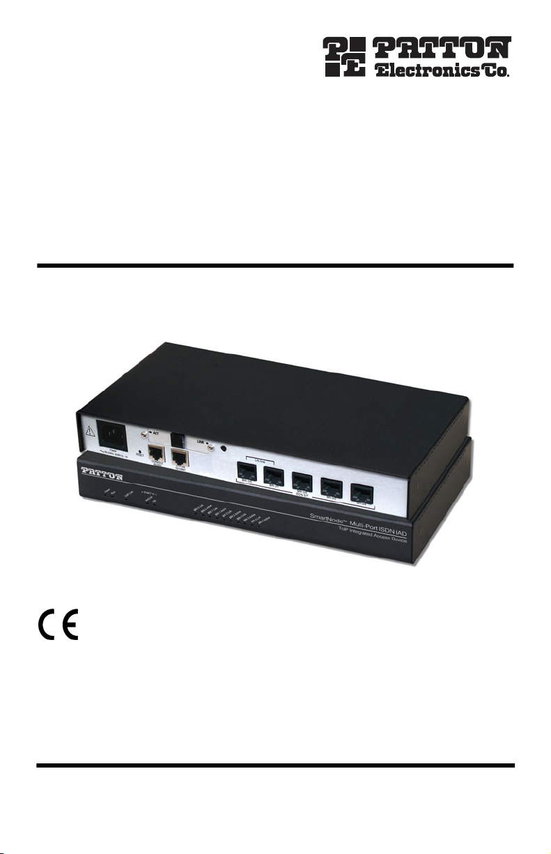
SmartNode 4650 Series
Multiport ISDN VoIP IAD
with G.SHDSL
Quick Start Guide
Approval —This device is approved for connection to the public ISDN telecommunication network,
over BRI/S0-ISDN interfaces.
Zulassung —Zugelassen für die Anschaltung an das öffentliche ISDN Telekommunikationnetz an
BRI/S0-ISDN Schnittstellen.
Aprobación —Este aparato está aprobado para conexión a red publica ISDN sobre interfaz BRI/S0.
Approbation —Cet appareil est approuve pour la connexion au reseau ISDN public avec les interfaces
BRI/S0.
Part Number: 07MSN4650-QS , Rev. C
Revised: June 24, 2009
Sales Office: +1 (301) 975-1000
Technical Support: +1 (301) 975-1007
E-mail: support@patton.com
WWW: www.patton.com
Page 2

2
•
WARNING
This device contains no user serviceable parts. The equipment shall be
returned to Patton Electronics for repairs, or repaired by qualified service personnel.
•
Mains Voltage: Do not open the case the when the power cord is
attached. Line voltages are present within the power supply when the
power cords are connected. The mains outlet that is utilized to power
the devise shall be within 10 feet (3 meters) of the device, shall be easily accessible, and protected by a circuit breaker.
•
Ensure that the power cable used meets all applicable standards for the
country in which it is to be installed, and that it is connected to a wall
outlet which has earth ground.
•
For units with an external power adapter, the adapter shall be a listed
Limited Power Source.
•
Hazardous network voltages are present in WAN ports regardless of
whether power to the unit is ON or OFF. To avoid electric shock, use
caution when near WAN ports. When detaching the cables, detach the
end away from the device first.
•
Do not work on the system or connect or disconnect cables during periods of lightning activity.
1.0 Power up the SmartNode
1. Connect the SmartNode to the mains (AC) power source with the power cable.
2. Wait until the Power LED stops blinking and remains constantly lit. Now the SmartNode is ready
to configure.
2.0 Connecting the SmartNode to your laptop PC
The interconnecting cables shall be acceptable for external use and shall be rated for
the proper application with respect to voltage, current, anticipated temperature, flammability, and mechanical serviceability.
CAUTION
SmartNode 4650 G.SHDSL Quick Start Guide
Page 3

3
–
+
1
2
V
,
1
.
2
5
A
A
C
T
L
I
N
K
Straight-through wired cable
LAN (ETH 0/0)
Laptop PC
Figure 1. Connecting to the PC
1. Connect the PC’s Ethernet port to LAN (ETH 0/0) port of the SmartNode 4650. The SmartNode 4650
Series is equipped with Auto-MDX Ethernet ports, so you can use straight-through Ethernet cables for host
or hub/switch connections. (See figure 1 .)
2. The SmartNode comes with a built-in DHCP server to simplify configuration. Therefore, to automatically
configure the PC for IP connectivity to the SmartNode, configure the laptop PC for DHCP. The SmartNode
will provide the PC with an IP address.
3. Check the connection to the SmartNode by executing the ping command from the PC command window
as follows:
ping 192.168.1.1
3.0 Configuring the desired IP address
3.1 Factory-default IP settings
The factory default configuration for the Ethernet interface IP addresses and netmasks are listed in table 1 .
Both Ethernet interfaces are activated upon power-up. LAN interface ETH 0/0 (LAN) provides a default DHCP
server. The WAN interface uses DHCP client to get the IP address and netmask automatically from the
service provider.
Table 1. Factory default IP address and network mask configuration
Item
LAN interface Ethernet 1 (ETH 0/0)
192.168.1.1 255.255.255.0
DHCP server address range (LAN) 192.168.1.10-192.168.1.19 255.255.255.0
If these addresses match with those of your network, go to section 4.0 “Connecting the SmartNode to the
network” on page 4. Otherwise, continue with the following sections to change the addresses and
network masks.
SmartNode 4650 G.SHDSL Quick Start Guide
IP Addresss Network Mask
Page 4
4
3.2 Login
1. To access the SmartNode, start the Telnet application on your PC. Type the default IP address into the
address field: 192.168.1.1 . Accessing your SmartNode via a Telnet session displays the login screen.
Type the factory default login: administrator and leave the password empty. Press the Enter key after the
password prompt.
login: administrator
password:<Enter>
192.168.1.1>
2. After you log in, your SmartNode will be running in operator execution mode (indicated by > character
in the command line prompt). To enter configuration mode, use the commands enable and configure .
192.168.1.1> enable
192.168.1.1# configure
192.168.1.1(cfg)#
4.0 Connecting the SmartNode to the network
The interconnecting cables shall be acceptable for external use and shall be rated for
the proper application with respect to voltage, current, anticipated temperature, flammability, and mechanical serviceability.
CAUTION
In general, the SmartNode will connect to the network via the WAN (ETH 0/0) port. This enables the SmartNode
to offer routing services to the PC hosts on LAN (ETH 0/1) port. The SmartNode 4650 Series provides an autoMDX feature for both Ethernet ports, so you can use a straight-through or cross-over cable to connect to a host or
a switch (see figure 2 ).
SmartNode 4650 G.SHDSL Quick Start Guide
Page 5

5
–
+
1
2V
, 1
.25A
A
C
T
L
I
N
K
LAN
Straight-through wired
Network
or crossover cable
WAN (DSL)
LAN (ETH 0/0)
Figure 2. Connecting the SmartNode to the network
1. You can check the connection with the ping command from the SmartNode to another host on the
local LAN.
172.16.1.99(if-ip)[eth_dsl]#ping <IP Address of the host>
Note If the WAN address is not set to DHCP, to ping a device outside your local LAN you must first configure
the default gateway. (For information on configuring the default gateway, refer to section “Set IP
addresses” in Appendix C, “Command Summary” of the
uration Guide
.)
SmartNode Series SmartWare Software Config-
SmartNode 4650 G.SHDSL Quick Start Guide
Page 6

6
5.0 Loading the configuration (optional)
Patton provides a collection of configuration templates on the CD-ROM shipped with your SmartNode device—
and also on the support page at www.patton.com/voip —one of which may be similar enough to your
application that you can use it to speed up configuring the SmartNode. Simply download the configuration note
that matches your application to your PC. Adapt the configuration as described in the configuration note to your
network (remember to modify the IP address) and copy the modified configuration to a TFTP server. The SmartNode can now load its configuration from this server.
Note Patton regularly adds new configuration templates to the collection at www.patton.com/voip , so if
you do not see your application on the CD-ROM, it may have been added to the website.
Note
If your application is unique and not covered by any of Patton’s configuration templates, you can man-
ually configure the SmartNode instead of loading a configuration file template. In that case, refer to
the
SmartNode Series SmartWare Software Configuration Guide
Node device.
In this example we assume an TFTP server resides on the host with the IP address 172.16.1.11 and the configuration file named SN.cfg resides in the root directory of the TFTP server.
172.16.1.99(if-ip)[eth_dsl]# copy tftp://172.16.1.11/SN.cfg star-
tup-config
Download...100%
172.16.1.99(if-ip)[eth_dsl]#
After you reboot the SmartNode the new startup configuration will become active.
for information on configuring the Smart-
When you issue the reload command, the SmartNode will ask if you want to copy the
running configuration to the startup configuration. Since you just downloaded a configuration file to the startup configuration you must answer this question with NO.
IMPORTANT
172.16.1.99(if-ip)[eth0]# reload
Running configuration has been changed.
Do you want to copy the 'running-config' to the 'startup-config'?
Press 'yes' to store, 'no' to drop changes : no
Press 'yes' to restart, 'no' to cancel : yes
The system is going down
Otherwise, the downloaded configuration will be overwritten and lost!
SmartNode 4650 G.SHDSL Quick Start Guide
Page 7

6.0 Additional Information
Refer to the SmartNode Series SmartWare Software Configuration Guide and the SmartNode Getting Started Guide
located on the CD-ROM shipped with your SmartNode device and available online at www.patton.com/man-
uals. For detailed information about:
• Installing, configuring, operating, and troubleshooting.
• Warranty, trademark & compliance
The CD-ROM also includes many freeware and shareware tools, including TFTP servers, and Telnet clients.
A.0 Customer and Technical Support
Toll-Free VoIP support: call sip:support@patton.com with a VoIP SIP client
Online support: www.patton.com
E-mail support: support@patton.com—answered within 1 business day
Telephone support:
• Standard: +1 (301) 975-1007 (USA), Monday–Friday: 8:00 am to 5:00 pm EST (1300 to
2200 UTC/GMT)
• Alternate: +41 (0)31 985 25 55 (Switzerland), Monday–Friday: 8:00 am to 5:00 pm CET (0900 to 1800
UTC/GMT)
Fax: +1 (253) 663-5693 (USA) or +41 (0)31 985 25 26 (Switzerland)
SmartNode 4650 G.SHDSL Quick Start Guide 7
Page 8

B.0 Compliance Information
B.1 Compliance
EMC Compliance:
• FCC Part 15, Class A
• EN55022, Class A
• EN55024
Safety Compliance:
• UL60950-1/CSA C22.2 No. 60950-1
• IEC/EN 60950-1
• AS/NZS 60950-1
PSTN Regulatory Compliance:
• TBR3
• AS/ACIF S031
• AS/ACIF S043 (G.SHDSL card)
B.2 Radio and TV interference
The SmartNode router generates and uses radio frequency energy, and if not installed and used properly—that
is, in strict accordance with the manufacturer’s instructions—may cause interference to radio and television
reception. The SmartNode router have been tested and found to comply with the limits for a Class A computing
device in accordance with specifications in Subpart B of Part 15 of FCC rules, which are designed to provide reasonable protection from such interference in a commercial installation. However, there is no guarantee that
interference will not occur in a particular installation. If the SmartNode router does cause interference to radio or
television reception, which can be determined by disconnecting the unit, the user is encouraged to try to correct
the interference by one or more of the following measures: moving the computing equipment away from the
receiver, re-orienting the receiving antenna and/or plugging the receiving equipment into a different AC outlet
(such that the computing equipment and receiver are on different branches).
B.3 ISDN compliance
This device is approved for connection to the public ISDN telecommunication network.
When this device is used in North America, it shall be connected to a Network Termination Device and not connected directly to an outside POTS line.
CAUTION
8 SmartNode 4650 G.SHDSL Quick Start Guide
Page 9

B.4 CE Declaration of Conformity
Product Description: SmartNode 4650 Series
This equipment conforms to the requirements of Council Directive 1999/5/EC on the approximation of the laws
of the member states relating to Radio and Telecommunication Terminal Equipment and the mutual recognition
of their conformity.
The safety advice in the documentation accompanying the products shall be obeyed.
The conformity to the above directive is indicated by the CE sign on the device.
The signed Declaration of Conformity can be downloaded from www.patton.com/certifications/.
B.5 Authorized European Representative
D R M Green
European Compliance Services Limited.
Avalon House, Marcham Road
Abingdon,
Oxon OX14 1UD, UK
B.6 Zulassung
Zugelassen fur die Anschaltung an das öffentliche ISDN Telekommunikationnetz an BRI/S0-ISDN Schnittstellen.
SmartNode 4650 G.SHDSL Quick Start Guide 9
Page 10

Copyright statement
Copyright © 2009, Patton Electronics Company. All rights reserved.
The information in this document is subject to change without notice. Patton Electronics assumes no
liability for errors that may appear in this document.
Trademarks statement
The term SmartNode is a trademark of Patton Electronics Company. All other trademarks presented in this docu-
ment are the property of their respective owners.
Warranty, Trademark, & Compliance Information
For warranty, trademark and compliance information, refer to the Models SN4650 Series Getting Started Guide
located on the CD-ROM that came with your VoIP Gateway Router or available online at www.patton.com.
In accordance with the requirements of council directive 2002/96/EC on Waste of
Electrical and Electronic Equipment (WEEE), ensure that at end-of-life you separate
this product from other waste and scrap and deliver to the WEEE collection system in
your country for recycling.
10 SmartNode 4650 G.SHDSL Quick Start Guide
Page 11

Notes
____________________________________________________________________
____________________________________________________________________
____________________________________________________________________
____________________________________________________________________
____________________________________________________________________
____________________________________________________________________
____________________________________________________________________
____________________________________________________________________
____________________________________________________________________
____________________________________________________________________
____________________________________________________________________
____________________________________________________________________
____________________________________________________________________
____________________________________________________________________
____________________________________________________________________
____________________________________________________________________
Page 12

Notes
____________________________________________________________________
____________________________________________________________________
____________________________________________________________________
____________________________________________________________________
____________________________________________________________________
____________________________________________________________________
____________________________________________________________________
____________________________________________________________________
____________________________________________________________________
____________________________________________________________________
____________________________________________________________________
____________________________________________________________________
____________________________________________________________________
____________________________________________________________________
____________________________________________________________________
____________________________________________________________________
12 SmartNode 4650 G.SHDSL Quick Start Guide
 Loading...