

Page 1
USER
Part # 07M460RC-A
Doc. #019081UA
Revised 3/13/98
MANUAL
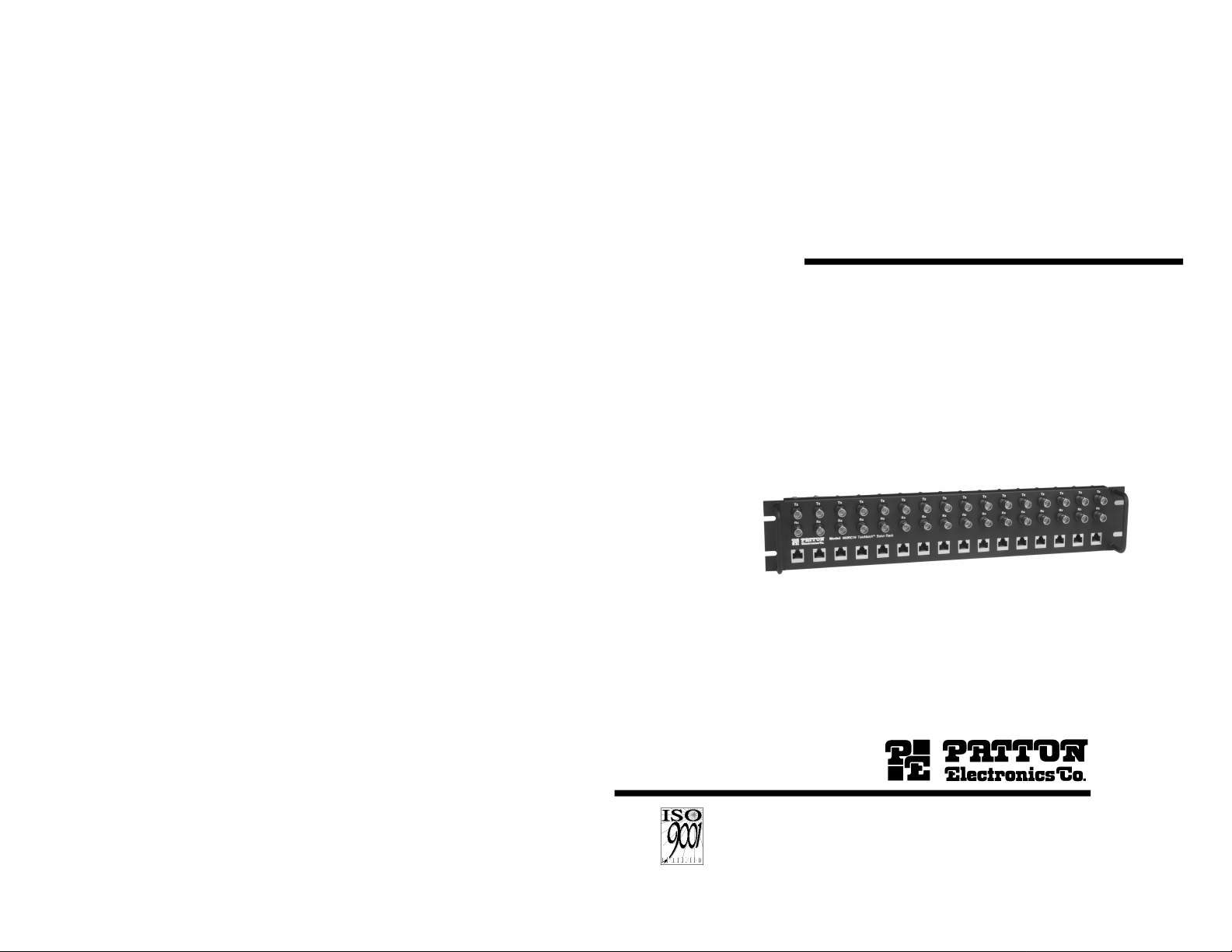
MODEL 460RC
Rack-Mounted G.703 Coax to
Twisted Pair
Adapters (BALUNs)
An ISO-9001
Certified Company
SALES OFFICE
(301) 975-1000
TECHNICAL SUPPORT
(301) 975-1007
http://www.patton.com
Page 2

1.0 WARRANTY INFORMATION
2.0 GENERAL INFORMATION
Thank you for your purchase of this Patton Electronics product.
This product has been thoroughly inspected and tested and is
warranted for One Year parts and labor. If any questions or problems
arise during installation or use of this product, please do not hesitate to
contact Patton Electronics Technical Support at (301) 975-1007.
2.1 FEATURES
• Connects 75 Ohm Dual Coax to 120 Ohm Twisted Pair
• Bi-Directional Signal Conversion According to CCITT G.703
• Data Rates up to 2.048 Mbps
• Low Profile Design
• Mounts in Standard 19” (48.3 cm) Rack
• No AC Power or Batteries Required
• Male or Female Coax BNC Connectors Available
• Strap Selectable Modular (RJ-45) Pinouts
2.2 DESCRIPTION
The Patton 460R Series G.703 balun panels match multiple sets of
dual 75 ohm coax connections to multiple 120 ohm twisted pair
connections. This function allows carriers to provide 120 ohm G.703
service to customers retaining 75 ohm CPE hardware. It also allows
carriers who have standardized on 75 ohm coax to provide 120 ohm
terminations to their customers (in keeping with European ONP
requirements).
Supporting E1 data rates to 2.048 Mbps, the Patton 460-R Series
panels bi-directionally match, not only signal impedance, but also the
pulse shapes of the signals according to the CCITT G.703 standard.
The Patton 460-R Series G.703 balun panels mount in a standard 19”
(48.3 cm) rack, and are available with either 1 to 16 modules per rack.
Patton Electronics warrants all Model 460RC components to be
free from defects, and will—at our option—repair or replace the product
should it fail within one year from the first date of shipment. This
warranty is limited to defects in workmanship or materials, and does not
cover customer damage, abuse or unauthorized modification. If this
product fails or does not perform as warranted, your sole recourse shall
be repair or replacement as described above. Under no condition shall
Patton Electronics be liable for any damages incurred by the use of
this product. These damages include, but are not limited to, the
following: lost profits, lost savings and incidental or consequential
damages arising from the use of or inability to use this product. Patton
Electronics specifically disclaims all other warranties, expressed or
implied, and the installation or use of this product shall be deemed an
acceptance of these terms by the user.
1.1 CE NOTICE
The CE symbol on your Patton Electronics equipment indicates that
it is in compliance with the Electromagnetic Compatibility (EMC)
directive and the Low Voltage Directive (LVD) of the Union European
(EU). A Certificate of Compliance is available by contacting Patton
Technical Support.
1.2 SERVICE AND SUPPORT
All warranty and non-warranty repairs must be returned freight
prepaid and insured to Patton Electronics. All returns must have a
Return Materials Authorization number on the outside of the shipping
container. This number may be obtained from Patton Electronics
Technical Service at (301) 975-1007; http://www.patton.com: or,
support@patton.com.
NOTE: Packages received without an RMA number will not be
accepted.
Patton Electronics' technical staff is also available to answer any
questions that might arise concerning the installation or use of your
Model 460RC. Technical Service hours: 8AM to 5PM EST, Monday
through Friday.
Page 3
3.1.1 Jumper Straps JP1, JP2, JP3, JP4, and JP7
3.0 CONFIGURATION
Each Model 460RC/F Module is equipped with four jumpers that
you may use to configure several grounding options. This section
shows the jumper locations and describes their functions.
3.1 SETTING THE JUMPER STRAPS
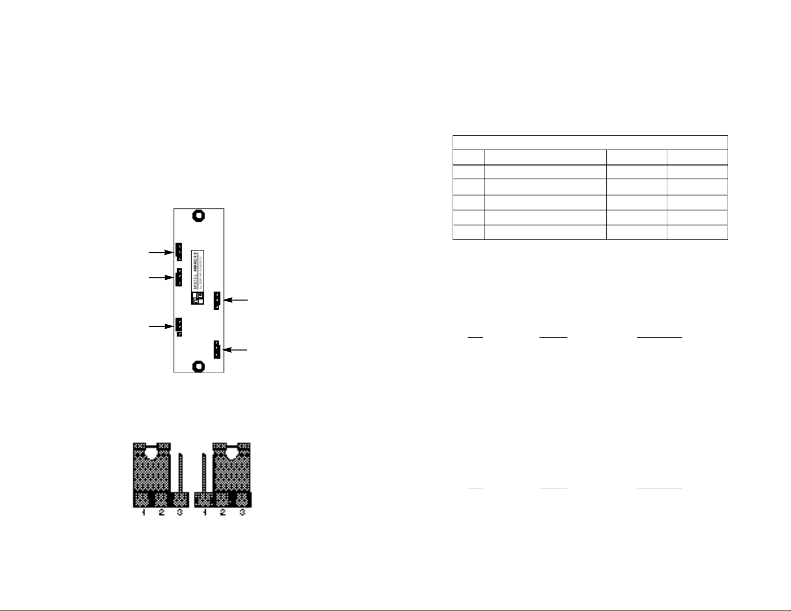
There are five configuration jumpers on the back side of the Model
460RC/F printed circuit board. These jumpers are labeled below and
on the PC board as “JP1”, “JP2”, “JP3”, “JP4”, and “JP7”. Figure 1,
below, shows their positions on the pc board as well as the relative pin
numbers on the jumpers.
Figure 2 (below) shows the orientation of the rear interface card
straps. Observe that the strap can either be on posts 1 and 2, or on
posts 2 and 3.
JP3
JP4
JP7
1
2
3
1
2
3
1
2
3
1
2
3
1
2
3
JP2
JP1
The jumper straps allow you to set shielding and grounding options
for the Model 460RC/F. The settings for each jumper strap are shown
briefly in the table below. Following this table are more detailed
explanations of each jumper.
INTERFACE CARD STRAP SUMMARY TABLE #1
Strap Function Position 1&2 Position 2&3
JP1 Coax TX Shield & RJ45 Pin 3 Open* Connected
JP2 Coax TX Shield & RJ-45 Shield Connected* Open
JP3 Coax RX Shield & RJ-45 Shield Connected* Open
JP4 Coax RX Shield & RJ-45 Pin 6 Open* Connected
JP7 RJ-45 Shield & Chassis Ground Connected* Open
* Indicates default setting
Jumper JP1: 75 Ohm TX Shield to 120 Ohm TX Pair Shield (Pin 3)
In the default “Connected” setting, the 75 Ohm transmit out coaxial
shield connects to RJ-45 pin 3, the transmit pair shield.
JP1 Setting Description
Position 1 & 2 Not Connected 75 Ohm TX shield not
connected to RJ-45 TX
pair shield (Pin 3).
Figure 1. Individual Model 460RC/F Card
Figure 2. Possible Positions for Model 460RC/F Jumpers
Position 2 & 3 Connected 75 Ohm TX shield
connected to RJ-45 TX
pair shield (Pin 3).
Jumper JP2: 75 Ohm Shield to 120 Ohm Overall Shield
In the default “Connected” setting, the 75 Ohm transmit out coaxial
shield connects to the RJ-45 overall foil shield.
JP2 Setting Description
Position 1 & 2 Connected 75 Ohm TX shield
connected to the RJ-45
overall foil shield.
Position 2 & 3 Not Connected 75 Ohm TX shield not
connected to the RJ-45
overall foil shield.
Page 4

Jumper JP3: 75 Ohm RX Shield to 120 Ohm Overall Shield
4.0 INSTALLATION
This section describes the functions of the Model 460RC16 rack
chassis, tells how to install front and rear Model 460RC/F Series cards
into the chassis, and how to connect to the twisted pair interface and
the serial interface.
4.1 THE MODEL 460R16 RACK CHASSIS
The Model 460R16 Rack Chassis (Figure 3, below) can
accomodate up to 16 G.703 75 Ohm coax to 120 Ohm RJ-45 baluns.
Measuring only 3.5” high, the Model 460R16 is designed to occupy only
2U in a 19” rack. Sturdy front handles allow the Model 460R16 to be
extracted and transported conveniently.
4.2 INSTALLING THE MODEL 460RC/F MODULE INTO THE
CHASSIS
The Model 460RC16 comprised of a 2U high rack chassis and
individually mountable G.703 balun modules. You may purchase a fully
populated 16 port rack or you may purchase individual modules. Refer
to Figure 4 as a guide and follow the steps below to install each Model
additional 460RC/F module into the rack chassis:
1. Slide the two star washers over the screws on each end of the
mount space.
2. Slide the Model 460RC/F pc board over the screws with the
BNC connectors facing downward. Then push the BNC
connectors and RJ-45 connector through the matching slots in
the front of the rack assembly.
3. Slide a plastic spacer over each screw to secure the pc board.
In the default “Connected” setting, the 75 Ohm receive in coaxial
shield connects to RJ-45 pin 6, the receive pair shield.
JP3 Setting Description
Position 1 & 2 Connected 75 Ohm RX shield
connected to the RJ-45
overall foil shield
Position 2 & 3 Not Connected 75 Ohm RX shield not
connected to the RJ-45
overall foil shield
Jumper JP4: 75 Ohm RX Shield to 120 Ohm Rx Pair Shield (Pin 6)
In the default “Connected” setting, the 75 Ohm coaxial shield
connects to the RJ-45 overall foil shield.
JP4 Setting Description
Position 1 & 2 Not Connected 75 Ohm RX shield not
connected to the RJ-45
RX pair shield (Pin 6)
Position 2 & 3 Connected 75 Ohm RX shield
connected to the RJ-45
RX pair shield (Pin 6)
Jumper JP7: RJ-45 Shield to Chassis Ground
In the default “Connected” setting, the RJ-45 overall shield
connects to chassis ground.
JP7 Setting Description
Position 1 & 2 Connected RJ-45 shield connects
to Frame Ground.
Position 2 & 3 Not Connected RJ-45 shield does not
connect to Frame
Ground.
Figure 3. Fully Populated Model 460RC16 Rack Chassis
Page 5

4. Install the lexan shield over the spacers.
4.4 CONNECTING THE 120 OHM RJ-45 PORTS
Star Washer (behind
460RC/F Module)
Spacer
Lexan Shield
Lock Washer
Hex Nut
Figure 4. Mounting a Model 460RC/F Module to the Rack
5. Secure the 460RC/F card assembly by connecting a lock
washer and hex nut on each screw.
4.3 CONNECTING THE 75 OHM BNC PORTS
The pin configuration of the 120 Ohm twisted pair port is shown
below:
RJ-45 Pin(s) Function
1................................TX Output
2................................TX Output
3................................TX Shield
4................................RX Input
5................................RX Input
6................................RX shield
7................................no connection
8................................no connection
Simply install the twisted pair wires by making the following
connections.
460RC/F Modules
G.703 Model 460RC/F
Instrument RJ-45 Pin No.
TX Output 4
TX Output 5
TX Shield 3
RX Input 1
RX Input 2
The 75 Ohm BNC ports on the front of the 460R16 are labeled
“TX” (Transmit Data Output) and “RX” (Receive Data Input). Simply
connect the G.703 lines as follows*:
G.703 Network Model 460RC/F
BNC Connector BNC Connectors
TX RX
RX TX
*NOTE: The total allowable cable lengths are subject to the
constraints of the ITU/CCITT G.703 recommendation. However,
we recommend a total patch cable length, including coaxial and
twisted pair cabling, of no more than 320 feet (200m).
RX Shield 6
*NOTE: The total allowable cable lengths are subject to the
constraints of the ITU/CCITT G.703 recommendation. However,
we recommend a total patch cable length, including coaxial and
twisted pair cabling, of no more than 320 feet (200m).
Page 6

APPENDIX A
APPENDIX B
PATTON ELECTRONICS MODEL 460RC
SPECIFICATIONS
Transmission Line: CCITT G.703 (unstructured)
Data Rate: 2.048 Mbps
75 Ohm Connection: Dual coax BNC connectors, male or
female (RG 59 or 2002 coax)
120 Ohm Connection: Shielded RJ-45 jack
Power Supply: none required
Link-to-Data Isolation: 500 volts AC/DC
Temperature Range: 32-122°F (0-50°C)
Dimensions (w/o handles): 19" Wide x 3.5" High x 1.9” Deep
(48.3 x 8.9 x 4.8 cm)
PATTON ELECTRONICS MODEL 460RC
FACTORY REPLACEMENT PARTS
AND ACCESSORIES
Model # Description
460R16......................Empty Balun Rack Panel
460RC/F ....................G.703 Balun Rack Module
05R16S460RC...........Lexan Shield
056345.......................Star Washer
0562-06......................Spacer
0561LW......................Lock Washer
055.............................Hex Nut
07M460RC.................Model 460RC User Manual
Page 7

APPENDIX C
APPENDIX D
PATTON ELECTRONICS MODEL 460RC/F
PIN ASSIGNMENTS
120 OHM TWISTED PAIR INTERFACE
RJ-45 Jack Pin No./Signal
1 - Transmit Data Out
2 - Transmit Data Out
3 - Transmit Data Shield
4 - Receive Data In
5 - Receive Data In
6 - Receive Data Shield
7 - no connection
8 - no connection
PATTON ELECTRONICS MODEL 460RC/F
BLOCK DIAGRAM
© Copyright 1998
Patton Electronics Company
All Rights Reserved
 Loading...