

Page 1

Model 3124
ADSL2+ IpDSLAM
User Manual
Important
This is a Class A device and is not intended for use in a residential environment.
Sales Office: +1 (301) 975-1000
Technical Support: +1 (301) 975-1007
E-mail: support@patton.com
WWW: www.patton.com
Part Number: 07M3124, Rev. A
Revised: March 16, 2012
Page 2

Patton Electronics Company, Inc.
7622 Rickenbacker Drive
Gaithersburg, MD 20879 USA
tel: +1 (301) 975-1000
fax: +1 (301) 869-9293
support: +1 (301) 975-1007
web: www.patton.com
e-mail: support@patton.com
Copyright © 2012, Patton Electronics Company. All rights reserved.
The information in this document is subject to change without notice. Patton
Electronics assumes no liability for errors that may appear in this document.
The software described in this document is furnished under a license and may
be used or copied only in accordance with the terms of such license.
Page 3

Summary Table of Contents
1 Introduction.................................................................................................................................................... 7
2 Hardware Installation.................................................................................................................................... 11
3 Configuration................................................................................................................................................ 19
4 Operation and Maintenance.......................................................................................................................... 42
5 Troubleshooting............................................................................................................................................ 47
6 Contacting Patton for assistance ................................................................................................................... 51
A Compliance information .............................................................................................................................. 54
B Specifications ................................................................................................................................................ 56
C Abbreviations ............................................................................................................................................... 62
5
Page 4

Table of Contents
Audience................................................................................................................................................................. 2
Structure................................................................................................................................................................. 2
Precautions............................................................................................................................................................. 3
Safety when working with electricity .................................................................................................................4
General observations .........................................................................................................................................5
Typographical conventions used in this document.................................................................................................. 6
General conventions .........................................................................................................................................6
Mouse conventions ...........................................................................................................................................6
1 Introduction.................................................................................................................................................... 7
Model 3124 ADSL2+ IpDSLAM Overview ............................................................................................................8
Features...................................................................................................................................................................8
Application..............................................................................................................................................................9
Detailed Description of the Model 3124 .................................................................................................................9
Module Functional Block Diagram ...................................................................................................................9
LEDs and Interfaces ........................................................................................................................................10
Cooling System ...............................................................................................................................................10
2 Hardware Installation.................................................................................................................................... 11
Pre-Installation......................................................................................................................................................12
Tools and Test Equipment Requirements .......................................................................................................12
Safety Requirement .........................................................................................................................................12
Electrostatic Discharge Protection ...................................................................................................................12
Hardware Installation ............................................................................................................................................13
Installation Overview ......................................................................................................................................13
Mounting the Model 3124 .............................................................................................................................13
Power and Ground Connections .....................................................................................................................15
DC Power Connection ..............................................................................................................................15
AC Power Connection (Option) ...............................................................................................................15
Ground Connection ..................................................................................................................................16
Connecting the ADSLx and POTS interfaces .................................................................................................16
Connecting the GBE trunk interface ...............................................................................................................17
RJ-45 Electrical Trunk Port ......................................................................................................................17
Console Port ...................................................................................................................................................18
3 Configuration................................................................................................................................................ 19
Provisioning a Management IP Port......................................................................................................................20
CLI .................................................................................................................................................................20
Web GUI ........................................................................................................................................................20
Configuration Import/Export................................................................................................................................21
CLI .................................................................................................................................................................21
Web GUI ........................................................................................................................................................23
6
Page 5

Model 3124 User Manual Table of Contents
A – Import File (Write Download Config To Flash) .................................................................................23
B – Import File (Load Remote Config to Running Config) ......................................................................25
C – Export File (Put Running Config to Remote TFTP Server) ...............................................................26
D – Save Running Config to Flash (System Config) .................................................................................27
E – Reload FLASH to Running Config .....................................................................................................28
F – Restore Factory Default ......................................................................................................................29
G – Flash Boot Point Configuration Select ...............................................................................................30
Firmware Update...................................................................................................................................................31
CLI .................................................................................................................................................................31
Web GUI ........................................................................................................................................................32
FTP Get In Progress ..................................................................................................................................32
Firmware Write In Progress ......................................................................................................................33
Firmware Write Successful ........................................................................................................................33
Software Configuration Overview..........................................................................................................................33
Configuration Management ............................................................................................................................34
Bridge Configuration ................................................................................................................................34
ADSL Configuration .................................................................................................................................35
Performance Management ..............................................................................................................................35
ADSL Performance Management Statistics ...............................................................................................36
Remote Network Monitoring (RMON) Feature .......................................................................................37
Fault Management ..........................................................................................................................................39
System Alarms ...........................................................................................................................................39
ADSL Alarms ............................................................................................................................................40
Loopback Testing ...........................................................................................................................................40
Cluster Feature ...............................................................................................................................................41
4 Operation and Maintenance.......................................................................................................................... 42
Maintenance Requirement ....................................................................................................................................43
Tools and Equipment Requirements ...............................................................................................................43
System Spares ..................................................................................................................................................43
Dispatching Maintenance Personnel ...............................................................................................................43
Electrostatic Discharge Protection ...................................................................................................................43
Routine Maintenance ......................................................................................................................................43
Powering the Model 3124 Up or Down................................................................................................................44
Powering Up the DSLAM ..............................................................................................................................44
Powering Down the DSLAM ..........................................................................................................................44
Controls and LED Indication................................................................................................................................44
3124 LEDs and Interfaces ...............................................................................................................................45
Replacing the Air Filter..........................................................................................................................................46
5 Troubleshooting............................................................................................................................................ 47
Introduction
..........................................................................................................................................................48
Resolving Problems Indicated Through LEDs.......................................................................................................48
Resolving Problems Indicated Through Alarms.....................................................................................................48
Procedures for Troubleshooting the Model 3124...................................................................................................48
7
Page 6

Model 3124 User Manual Table of Contents
Troubleshoot Model 3124 Power-Up Problems ..............................................................................................49
Troubleshoot ADSLx Service Problems ..........................................................................................................49
Troubleshoot POTS Service Problems ............................................................................................................49
Subscriber Service Problems ............................................................................................................................50
6 Contacting Patton for assistance ................................................................................................................... 51
Introduction..........................................................................................................................................................52
Contact information..............................................................................................................................................52
Warranty Service and Returned Merchandise Authorizations (RMAs)...................................................................52
Warranty coverage ..........................................................................................................................................52
Out-of-warranty service .............................................................................................................................52
Returns for credit ......................................................................................................................................52
Return for credit policy .............................................................................................................................53
RMA numbers ................................................................................................................................................53
Shipping instructions ................................................................................................................................53
A Compliance information .............................................................................................................................. 54
Compliance ...........................................................................................................................................................55
EMC ...............................................................................................................................................................55
Low-Voltage Directive (Safety) .......................................................................................................................55
PSTN Regulatory ............................................................................................................................................55
Radio and TV Interference (FCC Part 15) ............................................................................................................55
CE Declaration of Conformity..............................................................................................................................55
Authorized European Representative.....................................................................................................................55
B Specifications ................................................................................................................................................ 56
Physical Specifications...........................................................................................................................................57
Environmental Specifications ................................................................................................................................57
Power Specifications ..............................................................................................................................................57
Trunk Interface .....................................................................................................................................................58
Line Interface ........................................................................................................................................................58
POTS Splitter Module ..........................................................................................................................................59
Management Interface...........................................................................................................................................59
OAM&P...............................................................................................................................................................59
Ethernet/IP Functionality......................................................................................................................................60
ATM and Interworking Function (IWF)...............................................................................................................61
C Abbreviations ............................................................................................................................................... 62
Abbreviations ........................................................................................................................................................63
8
Page 7

List of Tables
1 General conventions . . . . . . . . . . . . . . . . . . . . . . . . . . . . . . . . . . . . . . . . . . . . . . . . . . . . . . . . . . . . . . . . . . . . . . 6
2 Mouse conventions . . . . . . . . . . . . . . . . . . . . . . . . . . . . . . . . . . . . . . . . . . . . . . . . . . . . . . . . . . . . . . . . . . . . . . . 6
3 Model 3124 LEDs . . . . . . . . . . . . . . . . . . . . . . . . . . . . . . . . . . . . . . . . . . . . . . . . . . . . . . . . . . . . . . . . . . . . . . 10
4 Model 3124 Interfaces . . . . . . . . . . . . . . . . . . . . . . . . . . . . . . . . . . . . . . . . . . . . . . . . . . . . . . . . . . . . . . . . . . . 10
5 Required Installation Tools and Materials . . . . . . . . . . . . . . . . . . . . . . . . . . . . . . . . . . . . . . . . . . . . . . . . . . . . . 12
6 Console Setting . . . . . . . . . . . . . . . . . . . . . . . . . . . . . . . . . . . . . . . . . . . . . . . . . . . . . . . . . . . . . . . . . . . . . . . . . 13
7 Ports 1-24 Pin Assignment . . . . . . . . . . . . . . . . . . . . . . . . . . . . . . . . . . . . . . . . . . . . . . . . . . . . . . . . . . . . . . . . 17
8 Ports 25-48 Pin Assignment . . . . . . . . . . . . . . . . . . . . . . . . . . . . . . . . . . . . . . . . . . . . . . . . . . . . . . . . . . . . . . . 17
9 Pin Assignment of Console Cable . . . . . . . . . . . . . . . . . . . . . . . . . . . . . . . . . . . . . . . . . . . . . . . . . . . . . . . . . . . 18
10 Firmware Update Procedure . . . . . . . . . . . . . . . . . . . . . . . . . . . . . . . . . . . . . . . . . . . . . . . . . . . . . . . . . . . . . . 31
11 ADSL PM Statistics . . . . . . . . . . . . . . . . . . . . . . . . . . . . . . . . . . . . . . . . . . . . . . . . . . . . . . . . . . . . . . . . . . . . . 36
12 ADSL PM Thresholds . . . . . . . . . . . . . . . . . . . . . . . . . . . . . . . . . . . . . . . . . . . . . . . . . . . . . . . . . . . . . . . . . . . 37
13 RMON ETH Statistics Variables . . . . . . . . . . . . . . . . . . . . . . . . . . . . . . . . . . . . . . . . . . . . . . . . . . . . . . . . . . . 37
14 RMON ETH History Control Variables . . . . . . . . . . . . . . . . . . . . . . . . . . . . . . . . . . . . . . . . . . . . . . . . . . . . . 38
15 Model 3124 Alarm Hierarchy . . . . . . . . . . . . . . . . . . . . . . . . . . . . . . . . . . . . . . . . . . . . . . . . . . . . . . . . . . . . . . 39
16 Required Installation Tools and Materials . . . . . . . . . . . . . . . . . . . . . . . . . . . . . . . . . . . . . . . . . . . . . . . . . . . . . 43
17 3124 Controls and LED Indication . . . . . . . . . . . . . . . . . . . . . . . . . . . . . . . . . . . . . . . . . . . . . . . . . . . . . . . . . 45
18 Problems Indicated by LEDs . . . . . . . . . . . . . . . . . . . . . . . . . . . . . . . . . . . . . . . . . . . . . . . . . . . . . . . . . . . . . . 48
19 Physical Specifications . . . . . . . . . . . . . . . . . . . . . . . . . . . . . . . . . . . . . . . . . . . . . . . . . . . . . . . . . . . . . . . . . . . 57
20 Environmental Specifications . . . . . . . . . . . . . . . . . . . . . . . . . . . . . . . . . . . . . . . . . . . . . . . . . . . . . . . . . . . . . . 57
21 Power Specifications . . . . . . . . . . . . . . . . . . . . . . . . . . . . . . . . . . . . . . . . . . . . . . . . . . . . . . . . . . . . . . . . . . . . . 57
22 Abbreviations . . . . . . . . . . . . . . . . . . . . . . . . . . . . . . . . . . . . . . . . . . . . . . . . . . . . . . . . . . . . . . . . . . . . . . . . . . 63
1
Page 8

List of Figures
1 Model 3124 Front Panel . . . . . . . . . . . . . . . . . . . . . . . . . . . . . . . . . . . . . . . . . . . . . . . . . . . . . . . . . . . . . . . . . . . 8
2 System application . . . . . . . . . . . . . . . . . . . . . . . . . . . . . . . . . . . . . . . . . . . . . . . . . . . . . . . . . . . . . . . . . . . . . . . 9
3 Model 3124 Module Functional Block Diagram . . . . . . . . . . . . . . . . . . . . . . . . . . . . . . . . . . . . . . . . . . . . . . . . 9
4 Model 3124 Front Panel . . . . . . . . . . . . . . . . . . . . . . . . . . . . . . . . . . . . . . . . . . . . . . . . . . . . . . . . . . . . . . . . . . 10
5 Mounting Bracket Orientation (Top View) . . . . . . . . . . . . . . . . . . . . . . . . . . . . . . . . . . . . . . . . . . . . . . . . . . . 14
6 Mounting Bracket Position for Standard Mount . . . . . . . . . . . . . . . . . . . . . . . . . . . . . . . . . . . . . . . . . . . . . . . 14
7 Model 3124 DC and AC Power Connections . . . . . . . . . . . . . . . . . . . . . . . . . . . . . . . . . . . . . . . . . . . . . . . . . 15
8 Model 3124 grounding screw on the rear panel . . . . . . . . . . . . . . . . . . . . . . . . . . . . . . . . . . . . . . . . . . . . . . . . 16
9 Model 3124 Line/POTS ports . . . . . . . . . . . . . . . . . . . . . . . . . . . . . . . . . . . . . . . . . . . . . . . . . . . . . . . . . . . . . 16
10 Trunk Port RJ-45 pin assignment . . . . . . . . . . . . . . . . . . . . . . . . . . . . . . . . . . . . . . . . . . . . . . . . . . . . . . . . . . . 17
11 Console Port RJ-45 pin assignment . . . . . . . . . . . . . . . . . . . . . . . . . . . . . . . . . . . . . . . . . . . . . . . . . . . . . . . . . 18
12 Pin assignment of Console Interface . . . . . . . . . . . . . . . . . . . . . . . . . . . . . . . . . . . . . . . . . . . . . . . . . . . . . . . . 18
13 DB Configuration Concept . . . . . . . . . . . . . . . . . . . . . . . . . . . . . . . . . . . . . . . . . . . . . . . . . . . . . . . . . . . . . . . 21
14 Database configuration menu in the Web GUI . . . . . . . . . . . . . . . . . . . . . . . . . . . . . . . . . . . . . . . . . . . . . . . . 23
15 Write Download Config to Flash: Get File . . . . . . . . . . . . . . . . . . . . . . . . . . . . . . . . . . . . . . . . . . . . . . . . . . . 23
16 Write Download Config to Flash: Write File . . . . . . . . . . . . . . . . . . . . . . . . . . . . . . . . . . . . . . . . . . . . . . . . . . 24
17 Write Download Config to Flash: Write Successful . . . . . . . . . . . . . . . . . . . . . . . . . . . . . . . . . . . . . . . . . . . . . 24
18 Write Download Config to Flash: Fail to Get File . . . . . . . . . . . . . . . . . . . . . . . . . . . . . . . . . . . . . . . . . . . . . . 24
19 Load Remote Config to Running Config: Get File . . . . . . . . . . . . . . . . . . . . . . . . . . . . . . . . . . . . . . . . . . . . . 25
20 Load Remote Config to Running Config: Write Successful . . . . . . . . . . . . . . . . . . . . . . . . . . . . . . . . . . . . . . . 25
21 Load Remote Config to Running Config: Fail to Get File . . . . . . . . . . . . . . . . . . . . . . . . . . . . . . . . . . . . . . . . 25
22 Put Running Config to Remote TFTP Server: Put File . . . . . . . . . . . . . . . . . . . . . . . . . . . . . . . . . . . . . . . . . . 26
23 Put Running Config to Remote TFTP Server: Put File Successful . . . . . . . . . . . . . . . . . . . . . . . . . . . . . . . . . . 26
24 Put Running Config to Remote TFTP Server: Put File Fail . . . . . . . . . . . . . . . . . . . . . . . . . . . . . . . . . . . . . . . 26
25 Save Running Config to Flash: Write Running Configuration . . . . . . . . . . . . . . . . . . . . . . . . . . . . . . . . . . . . . 27
26 Save Running Config to Flash: Write Successful . . . . . . . . . . . . . . . . . . . . . . . . . . . . . . . . . . . . . . . . . . . . . . . . 27
27 Load FLASH to Running Config: Load Configuration . . . . . . . . . . . . . . . . . . . . . . . . . . . . . . . . . . . . . . . . . . . 28
28 Load FLASH to Running Config: Load Configuration Successful . . . . . . . . . . . . . . . . . . . . . . . . . . . . . . . . . . 28
29 Restore Factory Default . . . . . . . . . . . . . . . . . . . . . . . . . . . . . . . . . . . . . . . . . . . . . . . . . . . . . . . . . . . . . . . . . . 29
30 Restore Successful . . . . . . . . . . . . . . . . . . . . . . . . . . . . . . . . . . . . . . . . . . . . . . . . . . . . . . . . . . . . . . . . . . . . . . . 29
31 Flash Boot Point Configuration Select . . . . . . . . . . . . . . . . . . . . . . . . . . . . . . . . . . . . . . . . . . . . . . . . . . . . . . . 30
32 Firmware update no action . . . . . . . . . . . . . . . . . . . . . . . . . . . . . . . . . . . . . . . . . . . . . . . . . . . . . . . . . . . . . . . . 32
33 Management Software Model . . . . . . . . . . . . . . . . . . . . . . . . . . . . . . . . . . . . . . . . . . . . . . . . . . . . . . . . . . . . . . 33
34 Cluster network topology - Star . . . . . . . . . . . . . . . . . . . . . . . . . . . . . . . . . . . . . . . . . . . . . . . . . . . . . . . . . . . . 41
35 Model 3124 Air Filter Location . . . . . . . . . . . . . . . . . . . . . . . . . . . . . . . . . . . . . . . . . . . . . . . . . . . . . . . . . . . . 46
1
Page 9

About this guide
This guide describes installing and operating the Patton Electronics Model 3124 ADSL2+ IpDSLAM.
Audience
This guide is intended for the following users:
• Operators
• Installers
• Maintenance technicians
Structure
This guide contains the following chapters and appendices:
• Chapter 1 on page 7 describes the Model 3124
• Chapter 2 on page 11 describes installing the Model 3124 hardware
• Chapter 3 on page 19 configuring the Model 3124 for use
• Chapter 4 on page 42 details how to power up and deactivate the Model 3124
• Chapter 5 on page 47 contains troubleshooting and maintenance information
• Chapter 6 on page 51 contains information on contacting Patton technical support for assistance
• Appendix A on page 54 contains compliance information for the Model 3124
• Appendix B on page 56 contains specifications for the Model 3124
• Appendix C on page 62 contains a list of abbreviations used in this document
For best results, read the contents of this guide before you install the NTU.
2
Page 10
Model 3124 User Manual
Precautions
Notes, cautions, and warnings, which have the following meanings, are used throughout this guide to help you
become aware of potential problems. Warnings are intended to prevent safety hazards that could result in personal injury. Cautions are intended to prevent situations that could result in property damage or
impaired functioning.
Note
WARNING
WARNING
CAUTION
CAUTION
A note presents additional information or interesting sidelights.
The shock hazard symbol and WARNING heading indicate a potential electric
shock hazard. Strictly follow the warning instructions to avoid injury caused
by electric shock.
The alert symbol and WARNING heading indicate a potential safety hazard.
Strictly follow the warning instructions to avoid personal injury.
The shock hazard symbol and CAUTION heading indicate a
potential electric shock hazard. Strictly follow the instructions to
avoid property damage caused by electric shock.
The alert symbol and CAUTION heading indicate a potential hazard. Strictly follow the instructions to avoid property damage.
3
Page 11

Model 3124 User Manual
Safety when working with electricity
•
Do not open the device when the power cord is connected. For systems
without a power switch and without an external power adapter, line volt-
WARNING
ages are present within the device when the power cord is connected.
•
For devices with an external power adapter, the power adapter shall be a
listed imited Power Source The mains outlet that is utilized to power the
device shall be within 10 feet (3 meters) of the device, shall be easily
accessible, and protected by a circuit breaker in compliance with local regulatory requirements.
•
For AC powered devices, ensure that the power cable used meets all applicable standards for the country in which it is to be installed.
•
For AC powered devices which have 3 conductor power plugs (L1, L2 &
GND or Hot, Neutral & Safety/Protective Ground), the wall outlet (or
socket) must have an earth ground.
•
For DC powered devices, ensure that the interconnecting cables are rated
for proper voltage, current, anticipated temperature, flammability, and
mechanical serviceability.
•
WAN, LAN & PSTN ports (connections) may have hazardous voltages
present regardless of whether the device is powered ON or OFF. PSTN
relates to interfaces such as telephone lines, FXS, FXO, DSL, xDSL, T1, E1,
ISDN, Voice, etc. These are known as “hazardous network voltages” and
to avoid electric shock use caution when working near these ports. When
disconnecting cables for these ports, detach the far end connection first.
•
Do not work on the device or connect or disconnect cables during periods
of lightning activity.
WARNING
WARNING
WARNING
This device contains no user serviceable parts. This device can only be
repaired by qualified service personnel.
If one has reason to open the chassis or case, then the precautions mentioned
above shall be followed. This includes both the warnings relating to disconnection of the input power, and the warnings relating to the disconnection of
WAN, LAN & PSTN ports.
This device is NOT intended nor approved for connection to the PSTN. It is
intended only for connection to customer premise equipment.
4
Page 12

Model 3124 User Manual
CAUTION
In accordance with the requirements of council directive 2002/
96/EC on Waste of Electrical and Electronic Equipment (WEEE),
ensure that at end-of-life you separate this product from other
waste and scrap and deliver to the WEEE collection system in
your country for recycling.
Electrostatic Discharge (ESD) can damage equipment and impair
electrical circuitry. It occurs when electronic printed circuit cards
are improperly handled and can result in complete or intermittent
failures. Do the following to prevent ESD:
•
Always follow ESD prevention procedures when removing and
replacing cards.
•
Wear an ESD-preventive wrist strap, ensuring that it makes
good skin contact. Connect the clip to an unpainted surface of
the chassis frame to safely channel unwanted ESD voltages to
ground.
•
To properly guard against ESD damage and shocks, the wrist
strap and cord must operate effectively. If no wrist strap is
available, ground yourself by touching the metal part of the
chassis.
General observations
• Clean the case with a soft slightly moist anti-static cloth
• Place the unit on a flat surface and ensure free air circulation
• Avoid exposing the unit to direct sunlight and other heat sources
• Protect the unit from moisture, vapors, and corrosive liquids
5
Page 13

Model 3124 User Manual
Typographical conventions used in this document
This section describes the typographical conventions and terms used in this guide.
General conventions
The procedures described in this manual use the following text conventions:
Table 1. General conventions
Convention Meaning
Garamond blue type
Futura bold type Commands and keywords are in boldface font.
Futura bold-italic type Parts of commands, which are related to elements already named by the user, are
Italicized Futura type Variables for which you supply values are in italic font
Futura type Indicates the names of fields or windows.
Garamond bold type Indicates the names of command buttons that execute an action.
< >
Are you ready? All system messages and prompts appear in the Courier font as the system
% dir *.* Bold Courier font indicates where the operator must type a response or command
Indicates a cross-reference hyperlink that points to a figure, graphic, table, or section heading. Clicking on the hyperlink jumps you to the reference. When you
have finished reviewing the reference, click on the Go to Previous View
button in the Adobe® Acrobat® Reader toolbar to return to your starting point.
in boldface italic font.
Angle brackets indicate function and keyboard keys, such as <SHIFT>, <CTRL>,
<C>, and so on.
would display them.
Mouse conventions
The following conventions are used when describing mouse actions:
Table 2. Mouse conventions
Convention Meaning
Left mouse button This button refers to the primary or leftmost mouse button (unless
you have changed the default configuration).
Right mouse button This button refers the secondary or rightmost mouse button (unless
you have changed the default configuration).
Point This word means to move the mouse in such a way that the tip of
the pointing arrow on the screen ends up resting at the desired location.
Click Means to quickly press and release the left or right mouse button
(as instructed in the procedure). Make sure you do not move the
mouse pointer while clicking a mouse button.
Double-click Means to press and release the same mouse button two times quickly
Drag This word means to point the arrow and then hold down the left or
right mouse button (as instructed in the procedure) as you move the
mouse to a new location. When you have moved the mouse pointer
to the desired location, you can release the mouse button.
6
Page 14

Chapter 1 Introduction
Chapter contents
Model 3124 ADSL2+ IpDSLAM Overview ............................................................................................................8
Features...................................................................................................................................................................8
Application..............................................................................................................................................................9
Detailed Description of the Model 3124 .................................................................................................................9
Module Functional Block Diagram ...................................................................................................................9
LEDs and Interfaces ........................................................................................................................................10
Cooling System ...............................................................................................................................................10
7
Page 15
Model 3124 User Manual 1 • Introduction
Model 3124 ADSL2+ IpDSLAM Overview
The Model 3124 is a 1.5U high box-type IP DSLAM with a rack-mountable enclosure. The system provides
24/48 ADSL/2/2+ ports and is able to provide the broadband data communication services and multimedia
services at the same copper line. The Model 3124 is capable of delivering very high speed data service; full-rate
of ADSL2+ for 48 subscribers with 1 Gigabit uplinks. With advanced QoS features, Model 3124 is ideal for
next generation broadband network to deliver rich video contents, DSL, POTS, and VoIP service over
ADSL2+ link.
The Model 3124 provides one uplink ports with electrical Gigabit Ethernet (GbE) interfaces. It contains a
fixed fan card and a dust filter. It is also suitable for small size application and can be easily deployed in remote
location, for instance, remote terminal, business parks, street cabinets, etc… to extend the service reach dis
tance.
Figure 1 shows the front panel view of the Model 3124.
-
Figure 1. Model 3124 Front Panel
Features
• Highly compact solution that provides 24/48 ADSL/2/2+ only by 1.5U space and stackable for higher port
density
• Equipped with fan and air filter, low power requirements plus full diagnostics and alarm reporting capabil-
ity
• Standard-based with remote configuration and software upgrade that help service providers minimize daily
operational costs
• Support multi-ADSL speed including ADSL, ADSL2, ADSL2+ via POTS/ISDN user interface
• Wide operating temperature range from -10°C ~ 65°C
• Provide one GBE trunk interface with electrical (RJ-45) port
• User-friendly CLI, web-based GUI, and EMS (NMS) through in-band channel for carrying out the
OAM&P of the system
• Support system software download via FTP for both local and remote terminals
• Support database export and import functionality via TFTP for configuration backup and restoration
• Support SNTP to automatically calibrate the time and date of the system
• Support on board thermal sensor to detect over temperature conditions with software configurable thresh-
olds that generate SNMP traps and syslog alarm entries
• Provide SSH (Secure Shell) for more secure remote operation
• Meet CE requirement
Model 3124 ADSL2+ IpDSLAM Overview 8
Page 16
Model 3124 User Manual 1 • Introduction
Application
The Model 3124 supports up to 48 ADSL/2/2+ lines per 1.5U box. Users can manage the system with
CLI/SNMP/Web GUI via in-band management channel.
Figure 2. System application
Detailed Description of the Model 3124
Module Functional Block Diagram
Figure 3. Model 3124 Module Functional Block Diagram
Application 9
Page 17
Model 3124 User Manual 1 • Introduction
After the DSL module aggregate 24/48 ports DSL traffic into the network processor card, the network processor terminates the ATM traffic into Ethernet packets through its SAR (Segmentation and Reassembly) function. The network processor also provides the Layer-2 Ethernet functions; it can support the mapping between
the ATM VCI and VLAN ID (802.1q) and priority queues (802.1p). The mapping functionality between
ATM PVC and VLAN ID include one PVC to one VLAN ID and multiple PVCs to one VLAN ID. And
these mappings can be configurable.
LEDs and Interfaces
Figure 4. Model 3124 Front Panel
Table 3. Model 3124 LEDs
LED Description
SYS To indicate the system operation status
ALM To indicate the system alarm status
GBE To indicate the optical trunk port status
DSL Status To indicate the DSL status for each DSL port.
GBE - Speed
(LED on RJ-45)
GBE - Link/Act
(LED on RJ-45)
To indicate the trunk port transmission speed
(Orange color LED on the Ethernet port)
To indicate the trunk port data activity status
(Green color LED on the Ethernet port)
Table 4. Model 3124 Interfaces
Interface Description
GBE Gigabit Ethernet electrical trunk port
Console RS-232 port connected to the terminal for monitoring and controlling the system.
POTS RJ-21 connector (50-pin dual row header) for connecting POTS lines.
LINE RJ-21 connector (50-pin dual row header) for connecting DSL lines.
Cooling System
The cooling system of the Model 3124 consists of a fixed fan card and a swappable air filter. The fan card has
four fans to blow air through the DSLAM for cooling. The air filter is for trapping air-bourn particulates. The
filter is field-installable and filed- replaceable.
Features:
• Built-in 4 DC fans with error indicating signal for monitoring the status of fan module
• The fan will be turned on when system temperature is higher than T°C and will be turned off when system
temperature is less than T-10°C (the temperature threshold T can be configured).
Detailed Description of the Model 3124 10
Page 18

Chapter 2 Hardware Installation
Chapter contents
Pre-Installation......................................................................................................................................................12
Tools and Test Equipment Requirements .......................................................................................................12
Safety Requirement .........................................................................................................................................12
Electrostatic Discharge Protection ...................................................................................................................12
Hardware Installation ............................................................................................................................................13
Installation Overview ......................................................................................................................................13
Mounting the Model 3124 .............................................................................................................................13
Power and Ground Connections .....................................................................................................................15
DC Power Connection ..............................................................................................................................15
AC Power Connection (Option) ...............................................................................................................15
Ground Connection ..................................................................................................................................16
In Central Office................................................................................................................................. 16
In Remote Cabinet.............................................................................................................................. 16
Connecting the ADSLx and POTS interfaces .................................................................................................16
Connecting the GBE trunk interface ...............................................................................................................17
RJ-45 Electrical Trunk Port ......................................................................................................................17
Console Port ...................................................................................................................................................18
11
Page 19

Model 3124 User Manual 2 • Hardware Installation
Pre-Installation
This section provides safety information to review before installing the Model 3124. The information includes
required installation tools, safety requirements, and electrostatic discharge protection.
Tools and Test Equipment Requirements
To install and maintain the Model 3124, you should have the tools and test equipment listed in table 5.
Table 5. Required Installation Tools and Materials
Item Required Purpose
Anti-static wrist strap Protect the Model 3124 system from electrostatic
discharge damage.
Hand tools Screw drivers for equipment removal and
replacement.
Wire cutter/stripper Prepare wires for electrical connections.
Accessories and hardware kit Screws, bolts, etc., for securing the equipment on
the desired location
Safety Requirement
To prevent possible serious injury, do not apply power to the Model 3124 system at the central office or any
remote site until you’ve completed all of the installation procedures and connected it to the external facilities.
Be cautious when turning on/off the Model 3124 system power.
Electrostatic Discharge Protection
The terminal cards contain static-sensitive components. When handling them, be sure to wear a properly
grounded anti-static wrist strap to prevent the damage from electrostatic discharge. If a wrist strap is not avail
able, hold all cards only by their edges or extractor handles. Do not touch any component or traces on the
cards. For future use, store cards in original shipped antistatic bags, or in an approved static-protected bag or
container.
To minimize the possible damage from electrostatic discharge, do not install the Model 3124 in cold, dry
places where static electricity can build up. Also, when handling cards, do not touch their rear-edge connector
traces. These electrical contact points should be kept free of body oils and other contaminants.
-
Pre-Installation 12
Page 20

Model 3124 User Manual 2 • Hardware Installation
Hardware Installation
The hardware installation for the Model 3124 is simple and without complex hardware setting. However, it
should be installed following the standard installation procedures. During installation, basic safety precautions
should always be taken, especially, be sure to wear an antistatic wrist strap to prevent static electricity from
damaging the system and injury to the operator. Handle electronic components as little as possible.
Installation Overview
The installation consists of the following procedures. Each procedure will be explained in detail in the following sections:
1. Mount the system into the desired location of a rack.
2. Connect to the DC power supply, and then check the voltage. Make sure the AC power is not connected
before wiring the power cable and grounding.
3. Connect the cable between system and MDF.
After executing the previous procedures, please check the cable connection robustness and correctness before
turning on the power supply.
4. Connect Console cable to COM port of a computer. Then, run the terminal program with the setting
shown below in table 6.
Table 6. Console Setting
Parameter Setting
Baud Rate: 9600 bps
Data bit: 8 bit
Parity: None
Stop bit: 1 bit
Flow Control: None
Terminal Protocol: VT100
Mounting the Model 3124
The position and orientation of the brackets depends on the rack used for mounting. The DSLAM can be
front-mounted in a standard channel rack (5-inch projection); and it can be shipped with the mounting brack
ets installed in one of three mounting positions or shipped loose (see figure 5 on page 14).
The mounting brackets can be rotated for use in wall mounting. Optional adhesive feet may be attached to thebottom of the chassis so that it can be placed on a desk or other smooth surface.
-
Hardware Installation 13
Page 21

Model 3124 User Manual 2 • Hardware Installation
Figure 5. Mounting Bracket Orientation (Top View)
After the site requirements have been verified, the chassis may be installed at the specified location. When
mounting the chassis, practice good safety habits. Use two or more people to secure the chassis. Relay rack
mounting normally requires at least two people. To mount the Model 3124:
1. Locate the chassis and obtain the appropriate chassis mounting hardware.
2. Determine and obtain the tools required for the chassis mounting hardware.
3. From the front of the relay rack, position the chassis in its relay rack mounting location.
4. Using the appropriate rack mounting hardware, secure the chassis in its relay location on both left and
right side of mounting bracket (see Figure 1-2).
Note
WARNING
The chassis should be empty during the chassis mounting procedures.
Remove any unit in the chassis, and store them according to staticsensitive device storage procedures.
Hazardous voltages may exist on the chassis. Always practice good
safety habits when wiring a live circuit or performing maintenance
.
Figure 6. Mounting Bracket Position for Standard Mount
Hardware Installation 14
Page 22

Model 3124 User Manual 2 • Hardware Installation
Power and Ground Connections
Figure 7. Model 3124 DC and AC Power Connections
DC Power Connection
The DC power interface is a 4-pin terminal block with polarity signs on the front panel of the DSLAM.
The Model 3124 can be powered from two –48V DC power supply. The DC power connector is a 4P terminal block; 2P is for accommodating one DC power input and other 2P is for accommodating another DC
power input. The DC power should be connected to a well-fused power supply.
After completing chassis installation, please apply power to the fused power distribution panel feeding the chassis. When using a DC voltmeter, please check for proper voltage: -72V ~ -36V DC, and make sure that the
polarity is correct.
Ensure that all power sources to the chassis (power distribution panel) are
WARNING
Note
turned off during the connection.
It is recommended that the -48VDC power be supplied directly and
independently by a power feeding system and also avoid having a par
allel or mutual connection with other -48VDC power supplier of
telecom equipment. This is to guarantee our products against inter
-
ferences by other equipment while they are working.
AC Power Connection (Option)
If your Model 3124 uses AC power, connect the AC power cord to the AC supply socket on the front panel of
the DSLAM (refer to
Figure 7), and plug the cord into the external power source. The voltage must be 100 to
240 VAC.
Hardware Installation 15
Page 23

Model 3124 User Manual 2 • Hardware Installation
Ground Connection
This section provides the grounding rule for the Model 3124. All remote system sites must be properly
grounded for optimum system performance.
In Central Office. There should be a CO GND that is adequately grounded. If the measured resistance from
the grounding screw (on the rear panel of the DSLAM, refer to Figure 1-4) to CO GND is less than 5 Ohm,
then it can be assumed that the system is well grounded. If the measured resistance is larger than 5 Ohm, it is
recommended to connect the grounding screw to CO GND using #14 or #12 AWG wire gauge conductor.
In Remote Cabinet. The Model 3124 should be grounded by connecting a #14 or #12 AWG conductor
between the grounding screw (on the rear panel of the DSLAM, refer to Figure 1-4) and the earth ground or
main grounding bar. The resistance between the chassis and the grounding bar should be less than 25 Ohm.
Figure 8. Model 3124 grounding screw on the rear panel
Connecting the ADSLx and POTS interfaces
The Model 3124 supports 24/48 ADSLx subscribers per box. There are four RJ-21 50-pin female connectors
on the front panel of the system. Two connectors are for the ADSL line and two connectors are for the POTS
interface.
To connect the subscriber lines, use cables with the RJ-21 50-pin male connector. When installing, just plug
the end of a cable with the RJ-21 50-pin male connector into the POTS or LINE interface female connector
on the front panel. The other side of the cable is generally tied to the MDF.
The figure below shows the Line/POTS port position of the system:
Figure 9. Model 3124 Line/POTS ports
Hardware Installation 16
Page 24

Model 3124 User Manual 2 • Hardware Installation
The pin assignment of Line/POTS interface is illustrated below (the numbers in the connector figures below
represent PIN numbers).
• For Ports 1-24:
Table 7. Ports 1-24 Pin Assignment
PIN
Port
1 2 3 4 5 6 7 8 - 18 19 20 21 22 23 24 25
Tip 1Tip 2Tip 3Tip 4Tip 5Tip 6Tip 7Tip 8- Tip 18Tip 19Tip 20Tip21Tip22Tip23Tip24X
PIN
Port
26 27 28 29 30 31 32 33 - 43 44 45 46 47 48 49 50
Ring 1Ring 2Ring 3Ring 4Ring 5Ring 6Ring 7Ring 8- Ring 18Ring 19Ring 20Ring21Ring22Ring23Ring24X
• For Ports 25-48:
Table 8. Ports 25-48 Pin Assignment
PIN
Port
PIN
Port
1 2 3 4 5 6 7 8 - 18 19 20 21 22 23 24 25
Tip 25Tip 26Tip 27Tip 28Tip 29Tip 30Tip 31Tip 32- Tip 42Tip 43Tip 44Tip45Tip46Tip47Tip48X
26 27 28 29 30 31 32 33 - 43 44 45 46 47 48 49 50
Ring 25Ring 26Ring 27Ring 28Ring 29Ring 30Ring 31Ring 32- Ring 42Ring 43Ring 44Ring45Ring46Ring47Ring48X
Connecting the GBE trunk interface
The system provides one trunk interface that is an electrical RJ-45 port.
RJ-45 Electrical Trunk Port
The pin assignment of RJ-45 connector on the trunk port is shown in the following figure and table.
LED A
LED B
1, 2 T/Rx+, T/Rx 3, 6 T/Rx+, T/Rx 4, 5 T/Rx+, T/Rx -
Pin 8 Pin 1
7, 8 T/Rx+, T/Rx -
Figure 10. Trunk Port RJ-45 pin assignment
Hardware Installation 17
Page 25

Model 3124 User Manual 2 • Hardware Installation
Console Port
The Console interface on the front panel is the main control interface of the Model 3124. Figure 11 shows the
RJ45 connector pin assignment:
1 2 3 4 5 6 7 8
12345678
3 4 6 Other pins
TX RX GND Not used
Figure 11. Console Port RJ-45 pin assignment
To connect the host PC to the console port, a RJ45 (male) connector-to-RS232 DB9 (female) connector cable
is required. The RJ45 connector of the cable is connected to the Console port of the DSLAM; the DB9 con
nector of the cable is connected to the PC COM port. The DTE relative pin assignment of the console cable is
shown below:
1
6
2
RD
TD
DGND
7
3
8
4
9
5
Figure 12. Pin assignment of Console Interface
Table 9. Pin Assignment of Console Cable
DB-9F RJ-45M Pin
-- 1
- 2
Pin 2 RD 3
Pin 3 TD 4
- 5
Pin 5 DGND 6
- 7
- 8
1
2
3 (RD)
4 (TD)
5
6 (DGND)
7
8
Hardware Installation 18
Page 26

Chapter 3 Configuration
Chapter contents
Provisioning a Management IP Port......................................................................................................................20
CLI .................................................................................................................................................................20
Web GUI ........................................................................................................................................................20
Configuration Import/Export................................................................................................................................21
CLI .................................................................................................................................................................21
Web GUI ........................................................................................................................................................23
A – Import File (Write Download Config To Flash) .................................................................................23
B – Import File (Load Remote Config to Running Config) ......................................................................25
C – Export File (Put Running Config to Remote TFTP Server) ...............................................................26
D – Save Running Config to Flash (System Config) .................................................................................27
E – Reload FLASH to Running Config .....................................................................................................28
F – Restore Factory Default ......................................................................................................................29
G – Flash Boot Point Configuration Select ...............................................................................................30
Firmware Update...................................................................................................................................................31
CLI .................................................................................................................................................................31
Web GUI ........................................................................................................................................................32
FTP Get In Progress ..................................................................................................................................32
Firmware Write In Progress ......................................................................................................................33
Firmware Write Successful ........................................................................................................................33
Software Configuration Overview..........................................................................................................................33
Configuration Management ............................................................................................................................34
Bridge Configuration ................................................................................................................................34
ADSL Configuration .................................................................................................................................35
Performance Management ..............................................................................................................................35
ADSL Performance Management Statistics ...............................................................................................36
Remote Network Monitoring (RMON) Feature .......................................................................................37
Fault Management ..........................................................................................................................................39
System Alarms ...........................................................................................................................................39
ADSL Alarms ............................................................................................................................................40
Loopback Testing ...........................................................................................................................................40
Cluster Feature ...............................................................................................................................................41
19
Page 27

Model 3124 User Manual 3 • Configuration
Provisioning a Management IP Port
This section describes how to use CLI commands or Web GUI to provision an IP port for the Model 3124.
Note For both CLI and Web Configuration Tool, the default login username and
password are:
Before changing the system IP address, you can connect to the DSLAM via console port and type in
the following CLI command to check current setting:
Command Explanation
enable Enter enable command mode.
show management all Display all system management port IP settings.
CLI
Use the following commands to provision an IP port using the CLI:
Command Explanation
enable Enter enable command mode.
configure Enter configure command mode.
management gbe <ipv4 address>
[netmask <netmask>]
management gbe vlan <vlan id> Restrict incoming VLAN tag of in-band manage-
route default <ipv4 address> Set IP address of the default gateway.
runningcfg write partition <number> Save new setting to memory (partition).
admin/admin.
Set in-band management port IP setting.
ment. This setting is optional, not mandatory.
Web GUI
Use the following commands to provision an IP port in the Web GUI:
1. On the menu tree, click on System > Board Setup. The Board Setup page displays.
2. Type in the new IP setting in the GBE (In Band) section for in-band IP provisioning.
3. Click on Modify to submit the modification.
4. Save the new setting to flash memory. On the menu tree, click on Maintenance > Database. The Database
Configuration page displays.
5. Click on the DB Config Select drop-down list and select Save Running Config to Flash. Select write flash
at Partition 1 or Partition 2. Then, click the Write_Running button. Wait for memory write success mes
sage.
Provisioning a Management IP Port 20
-
Page 28

Model 3124 User Manual 3 • Configuration
Configuration Import/Export
The Model 3124 provides the configuration preservation feature that the configuration database is stored in
flash memory (two partitions available). In addition to the configuration preservation feature, the Model 3124
also provides the configuration export/import feature.
Figure 13. DB Configuration Concept
CLI
Suppose that TFTP Server IP address is 172.16.100.181 and configuration file name is ‘testcfg’:
A – Import file from TFTP Server to the Download Config and then write Download Config to the Flash
(partition 1 or partition 2).
Example:
enable
configure
remotecfg login 172.16.100.181 get testcfg write partition <number>
B – Import file from TFTP Server to the Download Config and then load Download Config to the Running
Config.
Example:
enable
configure
remotecfg login 172.16.100.181 get testcfg load
Configuration Import/Export 21
Page 29

Model 3124 User Manual 3 • Configuration
C – Export: export file from Running config to the TFTP server.
Example:
enable
configure
runningcfg login 172.16.100.181 put testcfg
D –Save Running config to the Flash (partition 1 or partition 2).
Example:
enable
configure
runningcfg write partition <number>
E –Reload Flash data to the Running config
Example:
enable
configure
runningcfg load partition <number>
F–Set system configuration (current boot point) to factory default value
Example:
enable
configure
restore-factory
G –Select Configuration Flash Boot Point
Example:
enable
configure
runningcfg active partition <number>
Configuration Import/Export 22
Page 30

Model 3124 User Manual 3 • Configuration
Web GUI
On the menu tree, click on Maintenance > Database. The Database Configuration page is displayed. Select
the database configuration action you want to perform:
• “A – Import File (Write Download Config To Flash)” on page 23
• “B – Import File (Load Remote Config to Running Config)” on page 25
• “C – Export File (Put Running Config to Remote TFTP Server)” on page 26
• “D – Save Running Config to Flash (System Config)” on page 27
• “E – Reload FLASH to Running Config” on page 28
• “F – Restore Factory Default” on page 29
• “G – Flash Boot Point Configuration Select” on page 30
Figure 14. Database configuration menu in the Web GUI
A – Import File (Write Download Config To Flash)
Type in the TFTP Server IP address and the name of the file you want to download. Then click on Get File
button.
Figure 15. Write Download Config to Flash: Get File
Configuration Import/Export 23
Page 31

Model 3124 User Manual 3 • Configuration
Write downloaded Config to Flash in progress:
Figure 16. Write Download Config to Flash: Write File
Write to memory successfully:
Fail to Get File:
Figure 17. Write Download Config to Flash: Write Successful
Figure 18. Write Download Config to Flash: Fail to Get File
Configuration Import/Export 24
Page 32

Model 3124 User Manual 3 • Configuration
B – Import File (Load Remote Config to Running Config)
Type in the TFTP Server IP address and the name of the file you want to download. Then click on Get File
button.
Figure 19. Load Remote Config to Running Config: Get File
Load to Running Config successfully:
Fail to Get File:
Figure 20. Load Remote Config to Running Config: Write Successful
Figure 21. Load Remote Config to Running Config: Fail to Get File
Configuration Import/Export 25
Page 33

Model 3124 User Manual 3 • Configuration
C – Export File (Put Running Config to Remote TFTP Server)
Type in the TFTP Server IP address and the name of the file you want to export. Then click on Put File button.
Figure 22. Put Running Config to Remote TFTP Server: Put File
TFTP put file successfully:
TFTP put file fail:
Figure 23. Put Running Config to Remote TFTP Server: Put File Successful
Figure 24. Put Running Config to Remote TFTP Server: Put File Fail
Configuration Import/Export 26
Page 34

Model 3124 User Manual 3 • Configuration
D – Save Running Config to Flash (System Config)
Click on the drop-down list and select partition, and then click on Write_Running button to write running
configuration to Flash.
Figure 25. Save Running Config to Flash: Write Running Configuration
Write running config to Flash successfully:
Figure 26. Save Running Config to Flash: Write Successful
Configuration Import/Export 27
Page 35

Model 3124 User Manual 3 • Configuration
E – Reload FLASH to Running Config
Click on the drop-down list and select partition, and then click on LOAD_FLASH button to load configuration from Flash to Running Config.
Figure 27. Load FLASH to Running Config: Load Configuration
Load configuration from FLASH to Running Config successfully:
Figure 28. Load FLASH to Running Config: Load Configuration Successful
Configuration Import/Export 28
Page 36

Model 3124 User Manual 3 • Configuration
F – Restore Factory Default
Except out-band IP address and user account, all other configuration will be restored to factory default.
Click on Factory_Default button to restore factory default configuration.
Figure 29. Restore Factory Default
After loading default configuration to Flash successfully, you must click on the RESTART button to restart the
system.
Figure 30. Restore Successful
Configuration Import/Export 29
Page 37

Model 3124 User Manual 3 • Configuration
G – Flash Boot Point Configuration Select
Click on the Boot Config drop-down list and select the partition (Partition1 or Partition2) as the boot point.
Click on Apply and then restart the system. The system will restart and load the configuration in the partition
you select into the running configuration.
Figure 31. Flash Boot Point Configuration Select
Configuration Import/Export 30
Page 38

Model 3124 User Manual 3 • Configuration
Firmware Update
CLI
If you want to update firmware code, you must get the image file from FTP Server.
Suppose that the FTP Server IP address is 172.16.10.219 and the image filename is ‘vmlinux_
patton0.74B04’.
Example:
1. Enter the following commands in order to update the firmware for Model 3124.
Table 10. Firmware Update Procedure
Command Purpose
enable Enter enable mode.
configure Enter configuration mode.
firmware login 172.16.100.219 username
share password tg123
firmware upgrade vmlinux_patton0.74B04 Firmware upgrade may take a few minutes, don’t
exit Return to enable mode.
show firmware status When status returns “Upgraded already!”, you can
show firmware partition Show partition information.
Login to update the firmware.
turn off or reset the system during the process.
restart the system to run new firmware image. Once
you upgrade successfully, you can’t upgrade the sec
ond time unless you have restarted the system.
-
Current Version:0.74B04
Partition Version Date Status
------------------------------------------1 0.74B03 2007/10/12 -2 0.74B04 2007/10/26 Active
Note
The ‘Active’status of the firmware partition information means the
active partition for next time restart, not current running partition.
You can see which partition by referring to the Current Version.
2. The Model 3124 provides two firmware memory partitions. If you want to change the firmware partition
for booting, use the following commands (if you change to the non-active partition, system will restart
immediately):
Command Purpose
enable Enter enable mode.
configure Enter configuration mode.
firmware partition <number> Select partition 1 or 2 for next power-on.
Firmware Update 31
Page 39

Model 3124 User Manual 3 • Configuration
Web GUI
On the menu tree, click on Maintenance > Firmware Update. The Firmware Update page is displayed. Once
you have entered all the necessary values, click on the Firmware Update button to start updating the firmware.
Figure 32. Firmware update no action
Enter the following parameters:
• Firmware Update: Once you have typed in the parameter values, click on this button to start firmware
update.
• Remote FTP Server IP: Type in the IP address of the FTP server.
• Server User Name: Type in the ftp user name.
• Server Password: Type in the ftp password.
• File Name: Type in the firmware filename.
• Firmware Update Status: This field shows current status of firmware update process.
• Firmware Partition Select: Choose a firmware memory partition (Partition 1 or 2). If you change to the
other partition (not current partition), the system will restart immediately.
FTP Get In Progress
The following message is displayed during getting file from FTP server.
Firmware Update 32
Page 40

Model 3124 User Manual 3 • Configuration
Firmware Write In Progress
The Flash Write process may take a few minutes. You must not turn off or reset the system during the process.
Firmware Write Successful
When the Flash Write process has completed successfully, the Firmware Update Status shows “Firmware has
upgraded already”. You can now restart the system.
Software Configuration Overview
Note
For more detailed software configuration instructions, refer to the
Model 3124 Administrator’s Reference Guide available online at
www.patton.com/manuals/3124-arg.pdf and the Model 3124 Com
-
mand Line Reference Guide available online at www.pat-
ton.com/manuals/3124-cli.pdf.
The software architecture of the Model 3124 is shown in the figure below. It can be divided into three layers:
the management layer, the OAM&P layer, and the firmware layer.
Figure 33. Management Software Model
As in the figure, CLI shell, SNMP agent, and WEB server are in the top-most layer (management layer) of the
system software and offering OAM&P function of the DSLAM based on the conceptual management features
as follows:
• Configuration Management
• Performance Management
• Fault Management
Software Configuration Overview 33
Page 41

Model 3124 User Manual 3 • Configuration
The Model 3124 uses flash memory as the database (DB) to store system configuration parameters. The firmware layer includes ADSL drivers, Memory and I/O control, etc.
Features of the Management Interface include:
• Support CLI, SNMP (v1, v2c), and web-based GUI management interface through in-band channels
• Support up to 10 CLI sessions at the same time
• The in-band management connection of the system is the highest priority of all supported in-band traffic
categories
• Support Telnet interface for remote operators to login system operating console
• Support up to 32 configurable SNMP trap destinations and allow the SNMP traps to be sent to any speci-
fied SNMP aware device, for instance, Network management center
Configuration Management
The configuration management contains the following aspects:
• System Setup, such as setup for management IP address/net mask, GBE interface (including to enable/dis-
able and query the administrative/operational status of the trunk port), line port (including to enable/disable/reset ADSL port, query the administrative/operational status of the port, and bind profiles on a per
port basis), CLI session and timeout, Cluster, SNTP, IP routes, and user administration (including login
authorization and provides three security levels).
• Bridge Configuration (refer to “Bridge Configuration” on page 34)
• ADSL Configuration (see “refer to “ADSL Configuration” on page 35)
• ATM traffic management
• SNMP setup
The configuration management provides detecting and reporting to the operators through SNMP Trap for all
memory updates reflecting changes in the system configuration. It also provides logging the changes in the
operational state and making this information available (on-demand) to the operators over the operation inter
face. The system contains a database (DB) to store all the provisioning data so that the configuration can be
restored in re-booting. Authorized operators can query the DB to obtain configuration data.
Bridge Configuration
The bridge configuration of the Model 3124 includes the following aspects:
• Interface setup
• VLAN configuration: static VLAN, protocol based VLAN, VLAN translation, and IP/MAC anti-spoofing.
• Access Control: Filtering, VLAN priority remark, rate limit, and priority queue mapping.
• Forwarding database
• DSL Line Identify
• IGMP configuration
-
• IPoA configuration
Software Configuration Overview 34
Page 42

Model 3124 User Manual 3 • Configuration
ADSL Configuration
Configuration for an ADSLx user port is provisioned by the parameter set, which is a group of attributes that
determine the user port behaviors; and we call it as a profile. The Model 3124 provides a profile-based provi
sioning per the definition of ITUT G997.1 and RFC 2662 for ADSL line configuration data and a mechanism
to associate the ADSL port to these profiles. One or more ADSL lines may be configured to share parameters
of a single profile.
The ADSL profiles of Model 3124 include:
• Service Profile
The parameters include Rate adaptive mode selection, Min/max/planned bit rate, Interleaving Max delay,
and Minimum impulse noise protection.
• Spectrum Profile
The parameters include the Power management setting, Min/max/target noise margin, allowed ADSL
modes of operation, Carrier mask, RFI band data, Maximum nominal aggregate transmit power, Maximum
PSD level, PSD shape (for ADSL2+), Power back off initiation, and Maximum aggregate receive power.
• TCA Profile
The parameters include ESs, SESs, UASs for interval and day PM, and LOS, LOF, LOPWR, LOL, Error
Frame for interval PM only.
The system provides up to 120 Service profiles and Spectrum profiles respectively, and provides up to 16 TCA
profiles. One of the profiles is a fix default that cannot be modified; users are allowed to create, and edit the
other profiles. Each profile contains a parameter set for downstream and upstream direction respectively. Users
can also observe the actual values of these parameters through CLI, Web-GUI, or EMS.
The ADSL configuration also includes the function for user to query the line status, the physical layer status,
and the channel interface status for ATU-C and ATU-R. The status information includes the attenuation rate,
actual net data rate, the line attenuation, SNR margin, transmission power, actual interleaving delay, channel
characteristics per subcarrier, quiet line noise PSD, …etc.
Performance Management
Performance management supports performance monitoring by collecting and thresholding performance
parameter counters against 15-miniute intervals for each interface and module respectively. Users can query the
data of these parameters through CLI, Web-GUI, or EMS.
Performance statistics include the following:
1. Statistics for current interval:
A real-time aspect contains the reflection of the current value situation before the new interval. The current value includes values of current 15-min interval and current 1-day interval.
2. Statistics history at 15-minute basis:
The system stores previous 96 statistics of PM parameters at 15-min interval for retrieving.
3. Statistics history at 1-day basis:
The system stores previous 1 statistics of PM parameters at 1-day interval for retrieving.
Most of the performance parameter thresholds are user-programmable. The Model 3124 uses a threshold
crossing alert (TCA) to notify the management system when one of the counts during a measurement interval
exceeds its threshold.
Software Configuration Overview 35
Page 43

Model 3124 User Manual 3 • Configuration
The TCA contains the following information:
• Specific interface involved
• Error condition identifying the measurement type
• Value of the parameter
• Occurrence date and time of the event
The performance management also provides the traffic counter including transmitted packets, error packets
and discarded packets for each interface (network and subscriber interface) and ATM cell counter in both
transmit and receive direction. Users can observe these data through CLI, Web-GUI, or EMS.
ADSL Performance Management Statistics
The Model 3124 provides the following ADSL PM statistics:
Table 11. ADSL PM Statistics
Item Description
ATUC_LOS Loss of signal count
ATUC_LOF Loss of frame count
ATUC_LOM Loss of margin count
ATUC_LOL Loss of link count
ATUC_ES Errored Seconds
ATUC_SES Severely Errored Seconds
ATUC_UAS Unavailable Seconds
ATUC_ReInitCounter The number of times the modem left showtime and tried to re-ini-
tialize the line because of detection of a persistent defect
ATUC_FailedInitCounter The number of times the modem tries to initialize the line but fails.
ATUC_CU User Total Cell Count
ATUC_CD Delineated Total Cell Count
ATUC_HEC ATM Header Error Count
ATUC_IBE Idle Cell Bit Error Count
ATUC_CVS The counter associated with the number of Coding Violations
encountered by the channel.
ATUC_FECCS The counter associated with the number of corrected codewords
encountered by the channel.
ATUR_LOS Far End Loss of signal count
ATUR_LOF Far End Loss of frame count
ATUR_LOM Far End Loss of margin count
ATUR_LPR Far End Loss of power count
ATUR_ES Far End Errored Seconds
ATUR_SES Far End Severely Errored Seconds
ATUR_UAS Far End Unavailable Seconds
ATUR_HEC Far End ATM Header Error Count
ATUR_IBE Far End Idle Cell Bit Error Count
Software Configuration Overview 36
Page 44

Model 3124 User Manual 3 • Configuration
Table 11. ADSL PM Statistics
Item Description
ATUR_CVS The far end counter associated with the number of Coding Viola-
tions encountered by the channel.
ATUR_FECCS The far end counter associated with the number of corrected code
words encountered by the channel.
The Model 3124 provides the following ADSL PM thresholds:
Table 12. ADSL PM Thresholds
NE Threshold FE Threshold
15 min ES threshold 15 min ES threshold
15 min SES threshold 15 min SES threshold
15 min UAS threshold 15 min UAS threshold
15 min LOS threshold 15 min LOS threshold
15 min LOF threshold Not supported
Not supported 15 min LOPWR threshold
15 min LOL threshold Not supported
15 min ErrFrm threshold 15 min ErrFrm threshold
24 hour ES threshold 24 hour ES threshold
24 hour SES threshold 24 hour SES threshold
24 hour UAS threshold 24 hour UAS threshold
Remote Network Monitoring (RMON) Feature
The Model 3124 supports performance statistics defined in RMON MIB groups 1 (Ethernet statistics), 2 (history control), 3 (Ethernet history), 4 (alarm), 5 (event), and 6 (log) per RFC 2819 for all network uplink
10/100/1000 ports. The supported parameters are as follows:
Table 13. RMON ETH Statistics Variables
Variable Description
Rx DropEvents Monitoring rx dropped packets
Rx Bytes Monitoring rx bytes packets
Rx Packet Monitoring rx packets
Rx BroadcastPkts Monitoring rx broadcast packets
Rx MulticastPkts Monitoring rx multicast packets
Rx CRC Align Errors Monitoring rx error aligment packets
Rx Undersize Pkts Monitoring rx undersize packets
Rx Oversize Pkts Monitoring rx oversize packets
Rx Fragments Monitoring rx fragments packets
Rx Jabbers Monitoring rx jabber packets
Tx Collisions Monitoring tx single collision packets
Tx/Rx Pkts 64bytes Monitoring tx/rx 64 bytes
Software Configuration Overview 37
Page 45

Model 3124 User Manual 3 • Configuration
Table 13. RMON ETH Statistics Variables
Variable Description
Tx/Rx Pkts 65~127bytes Monitoring tx/rx 65 to 127 bytes
Tx/Rx Pkts 128~255bytes Monitoring tx/rx 128 to 255 bytes
Tx/Rx Pkts 256~511bytes Monitoring tx/rx 256 to 511 bytes
Tx/Rx Pkts 512~1023bytes
Tx/Rx Pkts 1024~1518bytes Monitoring tx/rx 1024 to 1518 bytes
Tx Bytes Monitoring tx bytes packets
Tx Packet Monitoring tx packets
Tx MulticastPkts Monitoring tx multicast packets
Tx BroadcastPkts Monitoring tx broadcast packets
Table 14. RMON ETH History Control Variables
Variable Description
HistoryDropEvents Monitoring rx dropped packets
Historybytes Monitoring rx bytes packets
HistoryPackets Monitoring rx packets
HistoryBroadcastPkts Monitoring rx broadcast packets
HistoryMulticastPkts Monitoring rx multicast packets
HistoryCRCAlignErrors Monitoring rx error aligment packets
HistoryUndersizePkts Monitoring rx undersize packets
HistoryOversizePkts Monitoring rx oversize packets
HistoryFragments Monitoring rx fragments packets
HistoryJabbers Monitoring rx jabber packets
HistoryCollisions Monitoring tx single collision packets
HistoryTxBytes Monitoring tx bytes
HistoryTxPackets Monitoring tx packets
HistoryTxMulticast
HistoryTxBroadcast Monitoring tx broadcast
HistoryUtilization Monitoring tx Utilization
Monitoring tx/rx 512 to 1023 bytes
Monitoring tx multicast
Software Configuration Overview 38
Page 46

Model 3124 User Manual 3 • Configuration
Fault Management
Fault management is conceptually partitioned into two levels: the system top level, and interface-specific level.
Both levels are alarm-level configurable and can be Major and Minor. All the alarms are mask-able.
Fault management provides the alarm output through hardware output interface (on the system front panel)
and visible indicator (LED). The alarm/status indications are automatically generated as a result of certain
events/conditions. The Model 3124 supports query of all current alarm status. It is also able to keep 256
records of historical alarms and events respectively.
The Model 3124 provides the ability to group alarms in a hierarchical alarm presentation scheme. Alarms of
the same rank can exist at the same time. A lower-ranking alarm will be demoted if a higher-ranking alarm is
raised for the same object. For example, if a far-end LOS is raised on a circuit and then a far-end LPR is raised
on the circuit, the LPR alarm stands and the LOS closes. The alarm hierarchy used in the Model 3124 system
is shown in the following table:
Table 15. Model 3124 Alarm Hierarchy
Priority Alarm Type
Highest all activation failures (ADSL_COMMF_FE or ADSL_NOPEER_FE)
—
—
Lowest near-end LOF or far-end LOF (near-end and far-end are independent;
far-end LPR
near-end LOS or far-end LOS
for example, FE-LOS does not restrain NE-LOF)
Note
LOM, LCD, and NCD are not included in the alarm hierarchy;
they’re treated independently.
Note
The PM counters LPR, LOS, and LOF follow the alarm hierarchy
rule. When these alarms exist at the same time, only the PM counter
of a higher-ranking alarm will count (the PM counters of other lowerranking alarms will not).
System Alarms
The Model 3124 provides the following System alarms:
• Fan Failure Alarm
• Above Temperature
• Below Temperature
• Self-test Fail
• DSP Fail - you can see which DSP chip is fail from the user interface (Web GUI, CLI, etc.). There is a
number 1 ~ 4 in the alarm message/description corresponding to the DSP chip 1 ~ chip 4
Software Configuration Overview 39
Page 47

Model 3124 User Manual 3 • Configuration
ADSL Alarms
The Model 3124 provides the following ADSL alarms:
• LOS (Loss of Signal) -Near End/Far End
• LOF (Loss of Frame) -Near End/Far End
• LOM (Loss of Margin) -Near End/Far End
• LCD (Loss of Cell Delineation) -Near End/Far End
• NCD (No Cell Delineation) -Near End/Far End
• LOPWR (Loss of Power) -Far End
• COMMF: Unable to communicate with peer modem -Far End
• NOPEER: No peer present – Far End
Loopback Testing
The Model 3124 supports ATM and ADSL loop diagnostics.
• ATM:
The system provides F5 end-to-end or segment loopback.
• ADSL:
The system provides Dual Ended Loop Testing (DELT) for each ADSL line on a per port basis, according
to the definition per section 8.12.3 of ITUT G992.3.
The following test parameters are supported:
- Channel Characteristics Function H(f) per subcarrier (CCF-ps),
- Quiet Line Noise PSD QLN(f) per subcarrier (QLN-ps),
- Signal-to-Noise Ratio SNR(f) per subcarrier (SNR-ps),
- Line Attenuation (LATN),
- Signal Attenuation (SATN),
- Signal-to-Noise Ratio Margin (SNRM),
- Attainable Net Data Rate (ATTNDR),
- Far-end Actual Aggregate Transmit Power (ACTATP),
- Near-End Actual Aggregate Transmit Power (ACTATP).
Software Configuration Overview 40
Page 48

Model 3124 User Manual 3 • Configuration
Cluster Feature
The Model 3124 supports Cluster feature that can make a group of NEs (network elements) work together as
a single NE from the management point of view. Operators can manage the NEs in a cluster, called cluster
nodes, via the same single IP address in terms of CLI, Web-based GUI or SNMP based management inter
faces. The Model 3124 currently provides cluster feature that a cluster can include up to four cluster members
(NEs). There are one Master and the other members are all Slaves in a cluster. The Master works as a gateway
of the Slaves, and it also can forward CLI/Web/SNMP commands to the destination Slave. The Slaves can exe
cute the commands and respond to the Master.
It uses star topology for conducting a Clustering Management group.
-
Figure 34. Cluster network topology - Star
Before you group a Master and a Slave IPDSLAM, some parameters need to be well configured:
1. Cluster domain name: The group name for a cluster must be the same on Master and Slave.
2. Cluster IP address: IP address to be used for remote management when Master and Slave are grouped
together.
3. NE cluster name: A name to identify Master or Slave.
4. Set private IP address on in-band port for both Master and Slave IPDSLAM. The private IP is used for
communication between Master and Slave. The management center actually uses Cluster IP address for
remote management.
5. Master and Slave need to be configured with same management VLAN.
6. The default gateway should be configured to the router that is aware how to route management traffic to
Management Center of the management network. The setting of Cluster default gateway should be the
same between Master and Slave.
Software Configuration Overview 41
Page 49

Chapter 4 Operation and Maintenance
Chapter contents
Maintenance Requirement ....................................................................................................................................43
Tools and Equipment Requirements ...............................................................................................................43
System Spares ..................................................................................................................................................43
Dispatching Maintenance Personnel ...............................................................................................................43
Electrostatic Discharge Protection ...................................................................................................................43
Routine Maintenance ......................................................................................................................................43
Powering the Model 3124 Up or Down................................................................................................................44
Powering Up the DSLAM ..............................................................................................................................44
Powering Down the DSLAM ..........................................................................................................................44
Controls and LED Indication................................................................................................................................44
3124 LEDs and Interfaces ...............................................................................................................................45
Replacing the Air Filter..........................................................................................................................................46
42
Page 50

Model 3124 User Manual 4 • Operation and Maintenance
Maintenance Requirement
Tools and Equipment Requirements
table 16 lists required tools and test equipment for the Model 3124 system maintenance.
Table 16. Required Installation Tools and Materials
Item Required Purpose
Anti-static wrist strap Protect the system from electrostatic discharge damage
Hand tool Screwdrivers for equipment removal and replacement
Wire cutter/stripper Prepare wires for electrical connections
Wire-wrap gun and bit Removing and replacing the system interconnection wires
Wires System interconnections to external facilities
VF transmission and signaling test sets Testing faulty POTS
Fuse and alarm panel For protection and simplifying troubleshooting
System Spares
Always keep spares for the DSLAM at each central office for replacement purposes. During the system troubleshooting procedures, certain cards at the central office and/or remote site will be required to be replaced.
Dispatching Maintenance Personnel
Some procedures in this manual involve end-to-end system testing, for which technicians are needed at each
remote site. The remote Model 3124 system sites are normally unattended, however, technicians should be dis
patched when needed. The Model 3124 system maintenance efforts and monitor the system for alarms during
those on-site operations.
Electrostatic Discharge Protection
The Model 3124 system contains static-sensitive components. Be sure to wear a properly grounded antistatic
wrist strap when handling them. Also, when removing and replacing a card, hold it either by its front ejector
handle or by its edges.
Do not touch its rear connector contacts, which must remain free of contaminants.
Routine Maintenance
Always monitor the Model 3124 system performance at the central office/ remote sites using the SNMP. It
allows users to view the current system status, alarm information and to take the necessary corrective action if a
problem is reported.
Also keep each Model 3124 system site free of dust and other pollutant that could affect system performance.
In addition, be sure to maintain the environment conditions at the central office and at each remote system
site. The ideal operating temperature is about 20ºC. The following is the acceptable operating condition range:
-10ºC to 60ºC and 0% to 95% humidity at 35ºC
-
Maintenance Requirement 43
Page 51

Model 3124 User Manual 4 • Operation and Maintenance
Powering the Model 3124 Up or Down
This section describes how to power up the DSLAM and how to power down the DSLAM.
Powering Up the DSLAM
1. Put on the antistatic wrist strap and connect it to a grounding point.
2. Ensure that the DSLAM is securely installed.
3. Ensure that the DSLAM ground strap is connected to a suitable ground point.
4. Ensure that –48 Vdc power is being supplied to the DSLAM. If you use AC power, ensure the AC power
is being supply.
5. Ensure that the POTS lines, subscriber lines, and alarm equipment are connected.
6. Wait for a minute, and then check the LEDs on the DSLAM. If the LEDs show some problem, refer to
“Resolving Problems Indicated Through LEDs” on page 48 for information on how to resolve problems
indicated through LEDs.
Powering Down the DSLAM
Powering down the DSLAM stops DSL service to subscrib-
CAUTION
ers. POTS service is not affected.
1. Put on the antistatic wrist strap and connect it to a grounding point.
2. Disconnect the AC power cord from the AC supply socket on the front panel.
Controls and LED Indication
The Model 3124 has simple controls and indicators on its front panel. The indicators show the current operating states of various system elements and serve as maintenance aids for local technicians at each site. The
remaining controls on the cards are also provided for local system testing and maintenance.
Powering the Model 3124 Up or Down 44
Page 52

Model 3124 User Manual 4 • Operation and Maintenance
3124 LEDs and Interfaces
Table 17. 3124 Controls and LED Indication
Front Panel of 3124
LED Color Indication/Condition
SYS Yellow At power on phase
Red Self-test fail
Green Normal Operation
ALM Yellow At power on phase
Red Major alarm set
Red - Flash Major and Minor alarm set
Yellow Minor alarm set
Green Normal Operation
DSL Status Green Port is activated and linked
Green - Flash Port is activated but not linked
Off Disabled
GBE - Speed*
(LED B on RJ-45)
GBE - Link/Act*
(LED A on RJ-45)
Interface Description
GBE Gigabit Ethernet electrical trunk port 1
Console RS-232 port connected to the terminal for monitoring and controlling the system.
POTS RJ-21 connector (50-pin dual row header) for connecting POTS lines.
LINE RJ-21 connector (50-pin dual row header) for connecting DSL lines.
Orange 100 / 1000 Mbps
Off 10 Mbps
Green Active
Green - Flash Inactive
Off Data Tx/Rx
Controls and LED Indication 45
Page 53
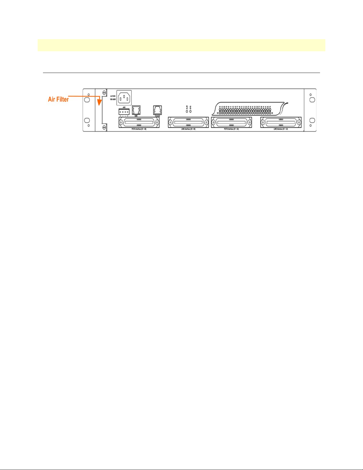
Model 3124 User Manual 4 • Operation and Maintenance
Replacing the Air Filter
This section provides procedures on how to replace the air filter (replace every three months).
Figure 35. Model 3124 Air Filter Location
Note
You must loosen the connection of the Air Filter Panel to the
DSLAM and pull out the Air Filter before replacing the air filter.
1. Put on the antistatic wrist strap and connect it to a grounding point.
2. Turn the screw on the Air Filter Panel counterclockwise until it loosens the connection of the panel to the
DSLAM. Remove the Air Filter Panel.
3. Pull the air filter out of the DSLAM.
4. Slide the replacement air filter into the air filter slot of the DSLAM.
5. Reinstall the Air Filter Panel.
Replacing the Air Filter 46
Page 54

Chapter 5 Troubleshooting
Chapter contents
Introduction..........................................................................................................................................................48
Resolving Problems Indicated Through LEDs.......................................................................................................48
Resolving Problems Indicated Through Alarms.....................................................................................................48
Procedures for Troubleshooting the Model 3124...................................................................................................48
Troubleshoot Model 3124 Power-Up Problems ..............................................................................................49
Troubleshoot ADSLx Service Problems ..........................................................................................................49
Troubleshoot POTS Service Problems ............................................................................................................49
Subscriber Service Problems ............................................................................................................................50
47
Page 55

Model 3124 User Manual 5 • Troubleshooting
Introduction
This chapter describes instructions for the Model 3124 system problems. These procedures may require the
presence of technicians at remote Model 3124 system sites and plus an operator at PC to monitor system
alarms by console or EMS during maintenance.
Resolving Problems Indicated Through LEDs
This section describes what to do to solve problems indicated by LEDs on the system front panel.
Table 18. Problems Indicated by LEDs
LED Activity Problem Action
SYS Not lit even
though DSLAM
is powered up
Red Self-test failed. There is a func-
ALM Red Major alarm set
Red - Flash Major and Minor alarm set
Yellow Minor alarm set
There is a power-up problem
with the system.
tional problem with the system.
Troubleshoot the DSLAM for power-up problems. (See
the Model 3124”
Replace the Model 3124.
See
Alarms”
See
Alarms”
See
Alarms”
“Procedures for Troubleshooting
on page 48).
“Resolving Problems Indicated Through
on page 48
“Resolving Problems Indicated Through
on page 48
“Resolving Problems Indicated Through
on page 48
Resolving Problems Indicated Through Alarms
Alarms of the system are viewed through CLI, Web GUI, JG-3124, or EMS. If an alarm indicates a problem,
refer to
“Procedures for Troubleshooting the Model 3124” on page 48 for troubleshooting procedures.
Procedures for Troubleshooting the Model 3124
When you follow a troubleshooting procedure, start from the first step of the procedure. If the first step does
not solve the problem, proceed to the next step; keep going through the steps until the problem is solved. Refer
to the list below for available troubleshooting procedures:
• “Troubleshoot Model 3124 Power-Up Problems” on page 49
• “Troubleshoot ADSLx Service Problems” on page 49
• “Troubleshoot POTS Service Problems” on page 49
• “Subscriber Service Problems” on page 50
Introduction 48
Page 56

Model 3124 User Manual 5 • Troubleshooting
Troubleshoot Model 3124 Power-Up Problems
Problem indication:
• the SYS LED on the front panel is not lit even though the DSLAM is powered up
• alarm that indicates a system power up problem
• subscribers connected to the DSLAM do not have DSL service; POTS service is ok
Procedure:
1. Check that the power cord is connected to thepower socket on the front panel, and the other end of the
cord is connected to a power outlet.
2. Check that the power feeds are connected to the DSLAM, and that power is present on the two power
feeds with correct polarity.
3. Replace the Model 3124.
4. Contact your provider.
Troubleshoot ADSLx Service Problems
Problem indication: No ADSLx service to the affected subscribers (POTS service is ok).
Procedure:
1. If all subscribers connected to the DSLAM are affected, and the SYS LED on the front panel is not lit,
check the both end of power cords:
– if one of the power cords is not connected, power up the DSLAM by plugging the power cord to the
power socket/power outlet.
– if the power cords are both connected, see “Troubleshoot Model 3124 Power-Up Problems” on page 49
to troubleshoot the DSLAM for power-up problem.
2. If all subscribers are affected, check the SYS LED on the front panel; if it is red, replace the DSLAM.
3. If only some subscribers are affected, identify the ports that have problems. Check that the subscribers are
connected to the line interfaces properly.
4. Contact your provider.
Troubleshoot POTS Service Problems
Problem indication: No POTS service to the affected subscribers (ADSLx service is ok).
Procedure:
1. Check the connection of the POTS lines at the POTS connector for the DSLAM.
2. Use a bridging connector to couple the POTS and subscriber lines. If this solves the problem, replace the
DSLAM.
3. Check the condition of the POTS lines and connectors.
Procedures for Troubleshooting the Model 3124 49
Page 57

Model 3124 User Manual 5 • Troubleshooting
Subscriber Service Problems
Problem indication: No POTS and ADSLx service to the affected subscribers.
Procedure:
1. Check the connection of the subscriber lines and POTS lines at the subscriber line connector for DSLAM
for subscribers that do not have POTS and ADSLx service.
If this step results in POTS service to the affected subscribers but there is still no ADSLx service to them,
refer to
“Troubleshoot ADSLx Service Problems” on page 49 to troubleshoot ADSLx service problems.
If this step results in ADSL service to the affected subscribers but there is still no POTS service to them,
refer to
“Troubleshoot POTS Service Problems” on page 49 to troubleshoot POTS service problems.
2. Use a bridging connector to couple the POTS and subscriber lines. If this results in POTS service to the
affected subscribers, contact your provider.
3. Check the condition of the subscriber lines and connectors.
Procedures for Troubleshooting the Model 3124 50
Page 58

Chapter 6 Contacting Patton for assistance
Chapter contents
Introduction..........................................................................................................................................................52
Contact information..............................................................................................................................................52
Warranty Service and Returned Merchandise Authorizations (RMAs)...................................................................52
Warranty coverage ..........................................................................................................................................52
Out-of-warranty service .............................................................................................................................52
Returns for credit ......................................................................................................................................52
Return for credit policy .............................................................................................................................53
RMA numbers ................................................................................................................................................53
Shipping instructions ................................................................................................................................53
51
Page 59

Model 3124 User Manual 6 • Contacting Patton for assistance
Introduction
This chapter contains the following information:
• “Contact information”—describes how to contact PATTON technical support for assistance.
• “Warranty Service and Returned Merchandise Authorizations (RMAs)”—contains information about the
RAS warranty and obtaining a return merchandise authorization (RMA).
Contact information
Patton Electronics offers a wide array of free technical services. If you have questions about any of our other
products we recommend you begin your search for answers by using our technical knowledge base. Here, we
have gathered together many of the more commonly asked questions and compiled them into a searchable
database to help you quickly solve your problems.
• Online support—available at www.patton.com.
• E-mail support—e-mail sent to support@patton.com will be answered within 1 business day
• Telephone support—standard telephone support is available Monday through Friday, from 8:00 A.M. to
5:00
P.M. EST (8:00 to 17:00 UTC-5), Monday through Friday by calling +1 (301) 975-1007
Warranty Service and Returned Merchandise Authorizations (RMAs)
Patton Electronics is an ISO-9001 certified manufacturer and our products are carefully tested before shipment. All of our products are backed by a comprehensive warranty program.
Note
Warranty coverage
Our products are under warranty to be free from defects, and we will, at our option, repair or replace the product should it fail within one year from the first date of shipment. Our warranty is limited to defects in workmanship or materials, and does not cover customer damage, lightning or power surge damage, abuse, or
unauthorized modification.
Out-of-warranty service
Patton services what we sell, no matter how you acquired it, including malfunctioning products that are no
longer under warranty. Our products have a flat fee for repairs. Units damaged by lightning or other catastro
phes may require replacement.
Returns for credit
Customer satisfaction is important to us, therefore any product may be returned with authorization within 30
days from the shipment date for a full credit of the purchase price. If you have ordered the wrong equipment or
you are dissatisfied in any way, please contact us to request an RMA number to accept your return. Patton is
not responsible for equipment returned without a Return Authorization.
If you purchased your equipment from a Patton Electronics reseller,
ask your reseller how you should proceed with warranty service. It is
often more convenient for you to work with your local reseller to
obtain a replacement. Patton services our products no matter how
you acquired them.
-
Introduction 52
Page 60

Model 3124 User Manual 6 • Contacting Patton for assistance
Return for credit policy
• Less than 30 days: No Charge. Your credit will be issued upon receipt and inspection of the equipment.
• 30 to 60 days: We will add a 20% restocking charge (crediting your account with 80% of the purchase
price).
• Over 60 days: Products will be accepted for repairs only.
RMA numbers
RMA numbers are required for all product returns. You can obtain an RMA by doing one of the following:
• Completing a request on the RMA Request page in the Support section at www.patton.com
• By calling +1 (301) 975-1000 and speaking to a Technical Support Engineer
• By sending an e-mail to returns@patton.com
All returned units must have the RMA number clearly visible on the outside of the shipping container. Please
use the original packing material that the device came in or pack the unit securely to avoid damage during ship
ping.
Shipping instructions
The RMA number should be clearly visible on the address label. Our shipping address is as follows:
-
Patton Electronics Company
RMA#: xxxx
7622 Rickenbacker Dr.
Gaithersburg, MD 20879-4773 USA
Patton will ship the equipment back to you in the same manner you ship it to us. Patton will pay the return
shipping costs.
Warranty Service and Returned Merchandise Authorizations (RMAs) 53
Page 61

Appendix A Compliance information
Chapter contents
Compliance ...........................................................................................................................................................55
EMC ...............................................................................................................................................................55
Low-Voltage Directive (Safety) .......................................................................................................................55
PSTN Regulatory ............................................................................................................................................55
Radio and TV Interference (FCC Part 15) ............................................................................................................55
CE Declaration of Conformity..............................................................................................................................55
Authorized European Representative.....................................................................................................................55
54
Page 62

Model 3124 User Manual A • Compliance information
Compliance
EMC
• FCC Part 15, Class A
• EN55022, Class A
• EN55024
Low-Voltage Directive (Safety)
• IEC/EN60950-1, 2nd edition
PSTN Regulatory
• This device is not intended nor approved for connection to the PSTN
Radio and TV Interference (FCC Part 15)
This device generates and uses radio frequency energy, and if not installed and used properly-that is, in strict
accordance with the manufacturer’s instructions-may cause interference to radio and television reception. The
device has been tested and found to comply with the limits for a Class A computing device in accordance with
specifications in Subpart B of Part 15 of FCC rules, which are designed to provide reasonable protection from
such interference in a commercial installation. However, there is no guarantee that interference will not occur
in a particular installation. If the device does cause interference to radio or television reception, which can be
determined by disconnecting the unit, the user is encouraged to try to correct the interference by one or more
of the following measures: moving the computing equipment away from the receiver, re-orienting the receiving
antenna and/or plugging the receiving equipment into a different AC outlet (such that the computing equipment and receiver are on different branches).
CE Declaration of Conformity
Patton Electronics, Inc declares that this device is in compliance with the essential requirements and other relevant provisions of Directive 1999/5/EC. The Declaration of Conformity may be obtained from Patton Electronics, Inc at www.patton.com/certifications
The safety advice in the documentation accompanying this device shall be obeyed. The conformity to the
above directive is indicated by CE mark on the device.
.
Authorized European Representative
D R M Green
European Compliance Services Limited.
Avalon House, Marcham Road
Abingdon,
Oxon OX14 1UD, UK
Compliance 55
Page 63

Appendix B Specifications
Chapter contents
Physical Specifications...........................................................................................................................................57
Environmental Specifications ................................................................................................................................57
Power Specifications ..............................................................................................................................................57
Trunk Interface .....................................................................................................................................................58
Line Interface ........................................................................................................................................................58
POTS Splitter Module ..........................................................................................................................................59
Management Interface...........................................................................................................................................59
OAM&P...............................................................................................................................................................59
Ethernet/IP Functionality......................................................................................................................................60
ATM and Interworking Function (IWF)...............................................................................................................61
56
Page 64

Model 3124 User Manual B • Specifications
Physical Specifications
Table 19. Physical Specifications
Item Value
Width 431.8 mm (17 in.) not including the
mounting brackets
Height 66 mm (1.5U)
Depth 275 mm
Weight 4.3 Kg
Rack Standard rack (19” or 23”)
Environmental Specifications
Table 20. Environmental Specifications
Operating Temperature -10 ~ 65°C
Relative Humidity 5% to 95% (non-condensing) at 35°C
Power Specifications
Item Value
Power Supply Interface DC: Dual A+B feeds, -72V ~ -36V, nominal – 48V.
Power Consumption Full load 48 ports: 96 W per system
Item Value
Table 21. Power Specifications
AC (optional): 100 ~ 240V/50 ~ 60Hz.
Full load 24 ports: 60 W per system
Physical Specifications 57
Page 65

Model 3124 User Manual B • Specifications
Trunk Interface
• Support IEEE 802.1X authentication for trunk interface.
• Support RJ45 connectors for uplink port.
• Electrical interface:
- Support IEEE 802.3 10/100/1000 Base-T auto-sensing GbE.
- Support auto-adaptive between full-duplex and half-duplex operation modes for 10 and 100 Mbpsopera-
tion speed on a per trunk port basis. The system only supports full-duplex mode for 1000 Mbps.
Line Interface
• Support a total of 24/48 subscriber lines and provisioning of the operation modes (ADSL/2/2+) on a per
port basis.
• Support ADSL operation modes that comply with ANSI T1.413, G.992.1 Annex A (POTS) and B
(ISDN), and G.992.2 G.lite.
• Support ADSL2 operation modes that comply with G.992.3 Annex A (POTS) and B (ISDN) respectively.
• Support ADSL2+ operation modes that comply with G.992.5 Annex A (POTS), B (ISDN), L (REDSL2+),
and M (extended upstream bandwidth over POTS) respectively.
• Support data rate:
- up to 25 Mbit/s downstream, 1.5 Mbit/s upstream (G.992.5),
- up to 3 Mbit/s upstream (Annex M), at integer multiples of 4 kbit/s for ADSL/ADSL2 and 8 kbit/s for
ADSL2+.
• Handshake procedure of each DMT ATU-C ADSLx circuit complies with ITU-T G.994.1.
• Support EOC and Overhead Channel Access defined in ITU-T G.992.5 and G.997.1
• Support ATM Transmission Convergence function defined in ITU-T G.992.5 Annex K
• Spectral Mask of transmitter signal complies with the PSD specified in ITU-T G.992.5 Annex A
• Support capability for the controllable spectrum bound defined in ITU-T G.992.5
• Support latency path function as defined in ITU-T G.992.5
• Support the capability of selectable pilot subcarrier for downstream direction specified in ITU-T G.992.5
• Physical layer management of each DMT xDSL circuit complies with ITU-T G.997.1.
• DMT xDSL subscriber interfaces support the following functions:
- Upstream and downstream non-overlapped mode
- Scrambling functionality
- FEC functionality
- Trellis coding
- Bit-swap
Trunk Interface 58
Page 66

Model 3124 User Manual B • Specifications
- Interleaving selection
• Support rate adaptation modes defined in ITU-T G.992.5 and G.997.1 including Manual, Rate Adaptive
At Init, and Dynamic Rate Adaptation modes
• Support Seamless Rate Adaptation (SRA) to on-line reconfigure the total data rate according to the line
condition
• The subscriber interface is able to support Fast Channel or Interleaved Channel independently for each
ADSL port.
• Support loop diagnostic function specified in ITU-T G.992.5 for each ADSL port independently (support
DELT loop diagnostics).
• Support detection of Dying Gasp message from ADSL CPE.
• Support power management link states (L0, L2, L3) defined in ITU-T G.992.5
• For power management, the transitions between L0 and L2 in downstream is on conditions according to
the control parameters specified in ITU-T G.992.5 and G.997.1
POTS Splitter Module
• Compliant with ETSI TS 101 952-1-1 option A for European, ETSI TS 101 952-1-3 for Annex B Euro-
pean ISDN, or ANSI 600.
• The splitter/low pass filter is passive element. Even the system is loss of power (power supply fails), the
POTS service is still OK.
Management Interface
• In-band management: provide all system OAM&P functions: software updates, configurations import/
export, and management system interaction through Ethernet trunk port.
OAM&P
• Configuration Management
• Performance Management
• Fault Management
• Status Monitoring
POTS Splitter Module 59
Page 67

Model 3124 User Manual B • Specifications
Ethernet/IP Functionality
• General Bridging Function
- Support IPv4 packet
- Support IEEE802.1d Ethernet bridge function between trunk Ether port and ATM VCs
- Support static source MAC table provisioning, automatic source MAC learning and block duplicate ones
- The system is able to maintain 4K entries in its own static MAC address table and to provision the sup-
ported number of MAC entries of a line port with a restriction of less than the maximum supported number, 128.
• VLAN
- Support IEEE 802.1q Port-based VLAN and Protocol-based VLAN
- Support 512 non-stacked VLAN-ID simultaneously ranging from 1 to 4095
- Support VLAN stacking and VLAN cross-connect
- Support IP Spoofing prevention
- Support MAC anti-Spoofing
- Support port isolation functionality. When port isolation is enabled, no Layer-2 bridging between differ-
ent ports (or subscriber lines) is supported in a VLAN
- Support static VLAN group and membership provisioning
• Multicast
- Support IP multicast forwarding and the multicast works well for RFC2684 bridged payload encapsula-
tion mode
- Support up to 256 multicast groups and 512 copies simultaneously
- Support profile-based Multicast Access Control (up to 48 profiles) and assign any profile to a subscriber
interface (the number of multicast channels within a profile is 256)
- Support to limit maximum number of IGMP groups joined per bridge port
- Support IGMP snooping/proxy per IGMP v1, v2, and v3
- Support selection between IGMP proxy and IGMP snooping
• ACL/Filtering
- Support Layer-2 frame filtering based on source/destination MAC addresses and EtherType
- Support Layer-3 filtering based on IP header including source/destination IP address, protocol ID, and
TCP/UDP destination port number
• Relay Functionality
- Support DHCP forward and DHCP relay agent option-82 functionality. The value within Circuit ID
and Remote ID sub-options is configurable.
- Support PPPoE relay
Ethernet/IP Functionality 60
Page 68

Model 3124 User Manual B • Specifications
• QoS
- The system is able to control the bandwidth occupied by broadcast, multicast, and unknown unicast
(flooding) traffic respectively on a per VLAN basis.
- Support rate-limit profile binding per bridge port
- Support Three Color Marking (TCM) policer
- Support Ethernet rate limit per bridge port
- Support ToS (type of service) /DiffServ (differentiated services) stripping and priority queuing
- Support DSCP mapping to 802.1p
- Support selectable adopted priority queue mechanisms according to Strict Priority Queue (SPQ) and
Weighted Fair Queue (WFQ)
- Support configurable mapping function between ATM PVC and 802.1p priority queue
- Support IP CoS technology
• ICMP
- Support ICMP (Internet Control Message Protocol) function; can send/respond the ICMP request mes-
sage to/from other system
• Support IPSec/L2TP/PPTP VPN pass-through function
ATM and Interworking Function (IWF)
• Support 8 PVCs per subscriber line; VPI range is from 0 to 255 and VCI range from 32 to 65535 (ATM
Forum UNI 3.1/4.0, PVCs only). The VPI and VCI value can be created and deleted via CLI, Web-GUI,
and EMS.
• Support multi-protocol encapsulation over ATM per RFC 2684 / RFC 1483 for bridged mode and routed
mode (IPoA).
• Comply with ITU-T I.361 UNI cell format and support AAL5 per ITU-T I.363.5.
• Support line-level fault management ITU-T Rec. I.610 OA&M F5 loopback on DSL ports including both
origination and reception/return of F5 loopback cells.
• Commit the supported ATM service categories in the increasing order of UBR, nrt-VBR, rt -VBR, and
CBR on a per port basis.
• Provide PCR (peak cell rate) configurable parameter for UBR and CBR service; PCR and SCR (sustainable
cell rate) configurable parameters for rt-VBR and nrt-VBR.
• Support upstream and downstreamtraffic shaping and policing on per PVC basis.
• Support profile-based ATM traffic management (up to 252 profiles with one default and 251 user-config-
urable profiles) and the downstream/upstream ATM profile assignments are independent
• Support PPPoE transparent forwarding and PPPoE intermediate agent
• Support PPPoE/PPPoA interworking as defined in section 3.5.4 of TR-101.
ATM and Interworking Function (IWF) 61
Page 69

Appendix C Abbreviations
Chapter contents
Abbreviations ........................................................................................................................................................63
62
Page 70

Model 3124 User Manual C • Abbreviations
Abbreviations
Table 22. Abbreviations
Abbreviation Explanation
ADSL Asymmetrical Digital Subscriber Line
ADSLx ADSL/ADSL2/ADSL2+
ANSI American National Standards Institute
ATM Asynchronous Transfer Mode
CLI Command Line Interface
DSLAM Digital Subscriber Line Access Multiplexer
EMS Element Management System
DSL Digital Subscriber Line
EMC Electromagnetic Compatibility
EMI Electromagnetic Immunity
ETSI European Telecommunications Standards Institute
Mbps Megabit per second
MDF Main Distribution Frame
LED Light Emitting Diode
POTS Plain Old Telephone Service
PSTN Public Switched Telephone Network
PVC Permanent Virtual Circuit
RMON Remote Monitoring
SNMP Simple Network Management Protocol
UNI User-Network Interface
Abbreviations 63
 Loading...