

Page 1
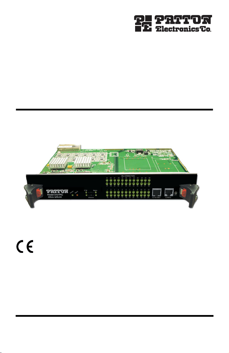
Model 3101RC
ADSL2/2+ Triple-Play Access
IPDSLAM Module
Quick Start Guide
Important—This is a Class A device and is intended for use in a light industrial environment. It is
not intended nor approved for use in an industrial or residential environment
.
Part Number: 07M3101RC-QS, Rev. A
Revised: October 22, 2008
Sales Office: +1 (301) 975-1000
Technical Support: +1 (301) 975-1007
E-mail: support@patton.com
WWW: www.patton.com
Page 2
• The Model 3101RC shall be installed in a restricted access location
accessible only to authorized personnel.
WARNING
• This unit contains no user-serviceable parts. Refer servicing to qualified personnel.
• When removing cards from a shelf under power, some of the components such as the DC converters may be extremely hot. Handle by the
card guides only.
• To prevent accidental electrical short circuits, align the card correctly
between the card guides before you insert it in the slot.
1.0 Pre-Installation
This section provides safety information to review before installing the Model 3101RC. The information includes
required installation tools, safety requirements, and electrostatic discharge protection.
1.1 Tools and Test Equipment Requirements
To install and maintain the Model 3101RC, you should have the tools and test equipment listed in
Table 1.
Item Required Purpose
Anti-static wrist strap Protect the Model 3101RC system from electrostatic discharge damage.
Hand tools Screw drivers for equipment removal and replacement.
Wire cutter/stripper Prepare wires for electrical connections.
Accessories and hardware kit Screws, bolts, etc., for securing the equipment on the desired location
Required Installation Tools and Materials
table 1
.
2
Model 3101RC Quick Start Guide
Page 3

1.2 Safety Requirement
To prevent possible serious injury, do not apply power to the Model 3101RC system at the central office or any
remote site until you’ve completed all of the installation procedures and connected it to the external facilities. Be
cautious when turning on/off the Model 3101RC system power.
1.3 Electrostatic Discharge Protection
The terminal cards contain static-sensitive components. When handling them, be sure to wear a properly
grounded anti-static wrist strap to prevent the damage from electrostatic discharge. If a wrist strap is not available, hold all cards only by their edges or extractor handles. Do not touch any component or traces on the cards.
For future use, store cards in original shipped antistatic bags, or in an approved static-protected bag or container.
To minimize the possible damage from electrostatic discharge, do not install the Model 3101RC in cold, dry
places where static electricity can build up. Also, when handling cards, do not touch their rear-edge connector
traces. These electrical contact points should be kept free of body oils and other contaminants.
2.0 Hardware Installation
The hardware installation for the Model 3101RC is simple and without complex hardware setting. However, it
should be installed following the standard installation procedures. During installation, basic safety precautions
should always be taken, especially, be sure to wear an antistatic wrist strap to prevent static electricity from damaging the system and injury to the operator. Handle electronic components as little as possible.
2.1 Connecting the ADSLx interfaces
The Model 3101RC supports 24/48 ADSL/2/2+ ports. There are two RJ-21 50-pin female connectors on the
front panel of the 3101RC TM card. One connector is for DSL ports 1~24; the other is for DSL ports 25~48.
When installing, just plug the end of a cable with the RJ-21 50-pin male connector into the DSL interface female
connector on the TM card. The other side of the cable is generally tied to the MDF.
Model 3101RC Quick Start Guide
3
Page 4
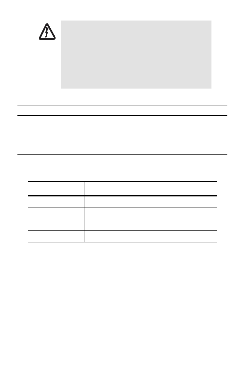
The pin assignment of ADSLx interface is illustrated below:
125
2650
1 2 3 4 5 6 7 8 - 18 19 20 21 22 23 24 25
Tip
Tip Tip Tip Tip Tip Tip Tip Tip Tip Tip Tip Tip Tip Tip
1 2 3 4 5 6 7 8 - 18 19 20 21 22 23 24 25
26 27 28 29 30 31 32 33 - 43 44 45 46 47 48 49 50
Ring Ring Ring Ring Ring Ring Ring Ring Ring Ring Ring Ring Ring Ring Ring
1 2 3 4 5 6 7 8 - 18 19 20 21 22 23 24 25
Figure 1.
Note
Tip 1 is for Port 1 in regard to the connector for 1~24 ports, or Port 25 in regard to the connector for
25~48 ports.
-
-X
Pin Assignment of DSL Interfaces
X
2.2 Connecting the GBE trunk interface
The Model 3101 has two configurable 10/100/1000 auto-negotiation copper GBE trunk interfaces. User can
switch any of the two GBE interfaces to PICMG 2.16 backplane or to 3101 TM card independently. By default, the
two GBE interfaces connect to 3101 TM card.
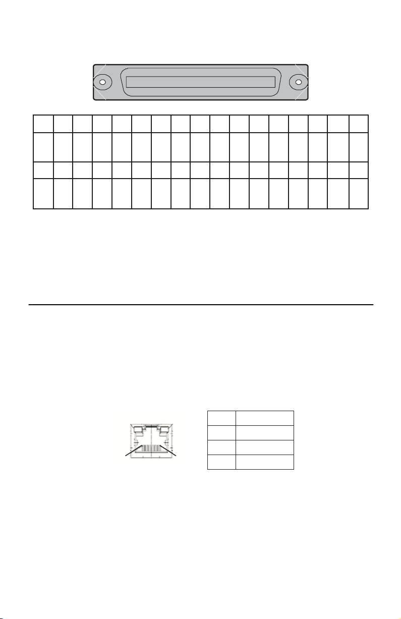
RJ-45 Electrical Trunk Port
The pin assignment of RJ-45 connector on the trunk port is shown in the following figure and table.
LED A
LED B
1, 2 T/Rx+, T/Rx 3, 6 T/Rx+, T/Rx 4, 5 T/Rx+, T/Rx -
Pin 8 Pin 1
7, 8 T/Rx+, T/Rx -
Figure 2.
4
Trunk Port RJ-45 pin assignment
Model 3101RC Quick Start Guide
Page 5

2.3 Ethernet Port (10/100 ENET) on Trunk Card
The Model 3101RC provides one RJ45 Jack (10/100 ENET) on the front panel of 3101RC card for Ethernet interface connection. The detailed pin assignment is shown in
PIN 1 PIN 8
LED A
LED B
figure 3
:
1 2 3 6 Other pins
TX + TX - RX + RX -
Figure 3.
Ethernet Port RJ-45 pin assignment
To connect the Ethernet interface to PC, the Ethernet crossover cable is required. The detailed pin assignment is
shown below:
Figure 4.
Ethernet crossover cable
Model 3101RC Quick Start Guide
5
Page 6

2.4 Console Port (CONFIG)
The Console interface (CONFIG) on the front panel of 3101RC card is the main control interface of the Model
3101RC. The RJ45 connector pin assignment follows the EIA-561 signal type used in RS-232 interface, and the
Model 3101 is a DCE Device. The following figure illustrated the DTE relative pin assignments in RJ45 connector:
1 2 3 4 5 6 7 8
12345678
4 5 6 Other pins
GND TxD RxD Not used
Figure 5.
Console Port RJ-45 pin assignment
To connect the host PC to the console port, a RJ45 (male) connector-to-RS232 DB9 (female) connector cable is
required. The RJ45 connector of the cable is connected to the COM port of the DSLAM; the DB9 connector of the
cable is connected to the PC COM port. The DTE relative pin assignment of the console cable is shown below:
RD
TD
DGND
1
6
2
7
3
8
4
9
5
Figure 6.
Pin assignment of Console Interface
1
2
3
4 (DGND)
5 (TD)
6 (RD)
7
8
6
Model 3101RC Quick Start Guide
Page 7

Table 2.
Signal Type Abbr. DB-9F RJ-45M Pin
Common Ground GND Pin 5 Pin 4
Transmitted Data TxD Pin 3 Pin 6
Received Data RxD Pin 2 Pin 5
Data Terminal Ready DTR Not used Not used
Data Set Ready DSR Not used Not used
Request To Send RTS Not used Not used
Clear To Send CTS Not used Not used
Carrier Detect DCD Not used Not used
Ring Indicator RI Not used NA
Pin Assignment of Console Cable (DTE Relative)
Model 3101RC Quick Start Guide
7
Page 8

3.0 Additional Information
Refer to the
online at
•
•
Model 3101RC Getting Started Guide
www.patton.com/manuals.
located on the CD-ROM shipped with your device and available
For detailed information about:
Installing, configuring, operating, and troubleshooting.
Warranty, trademark & compliance
A.0 Customer and Technical Support
Toll-Free VoIP support: call
Online support: www
E-mail support:
support@patton.com
Telephone support:
•
Standard: +1 (301) 975-1007 (USA), Monday–Friday: 8:00 am to 5:00 pm EST (1300 to
2200 UTC/GMT)
•
Alternate: +41 (0)31 985 25 55 (Switzerland), Monday–Friday: 8:00 am to 5:00 pm CET (0900 to 1800
UTC/GMT)
Fax:
+1 (253) 663-5693
sip:support@patton.com
.patton.com
(USA)
or +41 (0)31 985 25 26 (
with a VoIP SIP client
—answered within 1 business day
Switzerland)
8
Model 3101RC Quick Start Guide
Page 9

B.0 Compliance Information
B.1 Compliance
EMC Compliance:
•
EN55022, Class A
EN55024
•
Safety Compliance:
•
EN60950-1
B.2 CE Declaration of Conformity
We certify that the apparatus identified in this document conforms to the requirements of Council Directive
1999/5/EC on the approximation of the laws of the member states relating to Radio and Telecommunication
Terminal Equipment and the mutual recognition of their conformity.
The safety advice in the documentation accompanying this product shall be obeyed. The conformity to the above
directive is indicated by the CE sign on the device.
Model 3101RC Quick Start Guide
9
Page 10

Copyright statement
Copyright © 2008, Patton Electronics Company. All rights reserved.
The information in this document is subject to change without notice. Patton Electronics assumes no
liability for errors that may appear in this document.
Warranty
For warranty information, refer to the
your device or available online at
In accordance with the requirements of council directive 2002/96/EC on Waste of
Electrical and Electronic Equipment (WEEE), ensure that at end-of-life you separate
this product from other waste and scrap and deliver to the WEEE collection system in
your country for recycling.
Model 3101RC Getting Started Guide
www.patton.com
.
located on the CD-ROM that came with
10
Model 3101RC Quick Start Guide
Page 11

NOTES
____________________________________________________________________
____________________________________________________________________
____________________________________________________________________
____________________________________________________________________
____________________________________________________________________
____________________________________________________________________
____________________________________________________________________
____________________________________________________________________
____________________________________________________________________
____________________________________________________________________
____________________________________________________________________
____________________________________________________________________
____________________________________________________________________
____________________________________________________________________
____________________________________________________________________
____________________________________________________________________
Model 3101RC Quick Start Guide
11
Page 12

NOTES
____________________________________________________________________
____________________________________________________________________
____________________________________________________________________
____________________________________________________________________
____________________________________________________________________
____________________________________________________________________
____________________________________________________________________
____________________________________________________________________
____________________________________________________________________
____________________________________________________________________
____________________________________________________________________
____________________________________________________________________
____________________________________________________________________
____________________________________________________________________
____________________________________________________________________
____________________________________________________________________
12
Model 3101RC Quick Start Guide
 Loading...