

Page 1
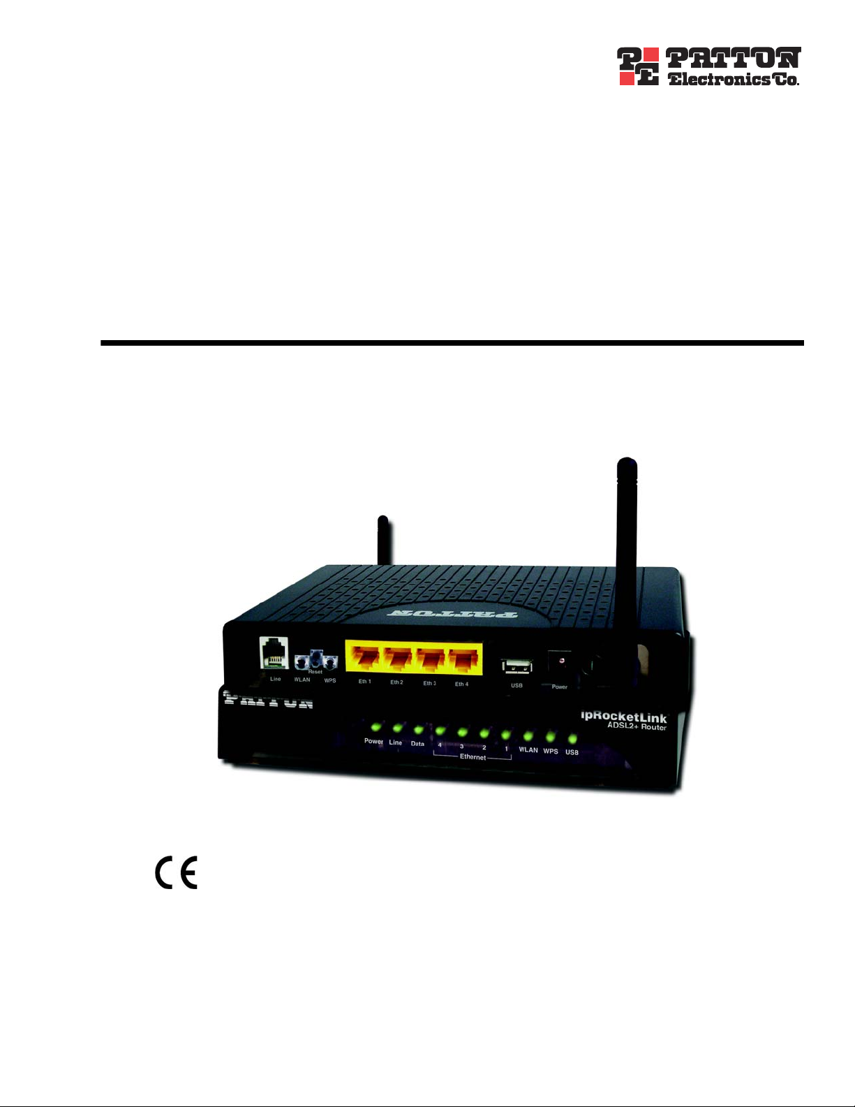
ipRocketLink™ Model 3101 Series
ADSL2+ WiFi Four-Port Router
Getting Started Guide
Important
This is a Class B device and is intended for use in a light industrial (commercial) or residential environment. It is not intended for use in
a heavy industrial environment.
Sales Office: +1 (301) 975-1000
Technical Support: +1 (301) 975-1007
E-mail: support@patton.com
WWW: www.patton.com
Part Number: 07M3101-GS, Rev. C
Revised: September 21, 2011
Page 2

Patton Electronics Company, Inc.
7622 Rickenbacker Drive
GaithersbuModel 3101, MD 20879 USA
Tel: +1 (301) 975-1000
Fax: +1 (301) 869-9293
Support: +1 (301) 975-1007
Web: www.patton.com
E-mail: support@patton.com
Trademark Statement
The term ipRocketLink is a trademark of Patton Electronics Company. All other trademarks presented in this document are the property of their respective owners.
Copyright © 2010-2011, Patton Electronics Company. All rights reserved.
The information in this document is subject to change without notice. Patton Electronics assumes no liability for errors that may appear in this document.
Warranty Information
Patton Electronics warrants all Model 3101 components to be free from defects, and
will—at our option—repair or replace the product should it fail within one year from
the first date of the shipment.
This warranty is limited to defects in workmanship or materials, and does not cover
customer damage, abuse or unauthorized modification. If the product fails to perform
as warranted, your sole recourse shall be repair or replacement as described above.
Under no condition shall Patton Electronics be liable for any damages incurred by the
use of this product. These damages include, but are not limited to, the following: lost
profits, lost savings and incidental or consequential damages arising from the use of or
inability to use this product. Patton Electronics specifically disclaims all other warranties, expressed or implied, and the installation or use of this product shall be deemed
an acceptance of these terms by the user.
Page 3

Summary Table of Contents
1 General Information...................................................................................................................................... 17
2 Applications Overview................................................................................................................................... 23
3 Installation and Initial Configuration........................................................................................................... 25
4 Device Access and Information ..................................................................................................................... 31
5 Advanced Configuration ............................................................................................................................... 37
6 Wireless Configuration ................................................................................................................................. 90
7 System Management.................................................................................................................................... 105
8 Contacting Patton for assistance ................................................................................................................. 112
A Compliance ................................................................................................................................................ 115
B Specifications .............................................................................................................................................. 117
3
Page 4

Table of Contents
Summary Table of Contents ........................................................................................................................... 3
Table of Contents ........................................................................................................................................... 4
List of Figures ................................................................................................................................................. 9
List of Tables ................................................................................................................................................ 12
About this guide ........................................................................................................................................... 13
Audience............................................................................................................................................................... 13
Structure............................................................................................................................................................... 13
Precautions........................................................................................................................................................... 14
Safety when working with electricity ...............................................................................................................15
General observations .......................................................................................................................................16
Typographical conventions used in this document................................................................................................ 16
General conventions .......................................................................................................................................16
1 General Information...................................................................................................................................... 17
Model 3101 Series Overview.................................................................................................................................18
Features ..........................................................................................................................................................18
Models ............................................................................................................................................................18
Front Panel............................................................................................................................................................19
LEDs ..............................................................................................................................................................19
Rear Panel .............................................................................................................................................................21
Ports ...............................................................................................................................................................22
2 Applications Overview................................................................................................................................... 23
Typical applications...............................................................................................................................................24
3 Installation and Initial Configuration........................................................................................................... 25
Installation Overview.............................................................................................................................................26
Planning the Installation........................................................................................................................................26
Location requirements ....................................................................................................................................26
Wireless operation .....................................................................................................................................26
Installing the Model 3101 .....................................................................................................................................27
Resetting the Model 3101 .....................................................................................................................................28
Configuration Overview ........................................................................................................................................28
Setting Up the 3101 for Configuration..................................................................................................................29
WAN and LAN Connections ..........................................................................................................................29
WAN ........................................................................................................................................................29
LAN ..........................................................................................................................................................29
PC Network Configuration ............................................................................................................................30
Windows XP .............................................................................................................................................30
Linux ........................................................................................................................................................30
4 Device Access and Information ..................................................................................................................... 31
Overview ...............................................................................................................................................................32
4
Page 5

Model 3101 Series Getting Started Guide Table of Contents
Logging In.............................................................................................................................................................32
Viewing Device Information .................................................................................................................................33
Summary ........................................................................................................................................................33
WAN Interface ...............................................................................................................................................33
Statistics ..........................................................................................................................................................33
LAN ..........................................................................................................................................................33
WAN ........................................................................................................................................................34
xTM .........................................................................................................................................................34
xDSL ........................................................................................................................................................35
xDSL BER Test ..................................................................................................................................35
Route ..............................................................................................................................................................36
ARP ................................................................................................................................................................36
DHCP ............................................................................................................................................................36
5 Advanced Configuration ............................................................................................................................... 37
Overview ...............................................................................................................................................................39
Layer2 Interface Setup ...........................................................................................................................................39
WAN Service Setup...............................................................................................................................................40
PPP over Ethernet (PPPoE) ............................................................................................................................41
MAC Encapsulation Routing (MER) (IPoE) ..................................................................................................45
PPP over ATM (PPPoA) .................................................................................................................................48
IP over ATM (IPoA) .......................................................................................................................................52
Bridging ..........................................................................................................................................................55
3G WAN Service Setup.........................................................................................................................................56
LAN Setup ............................................................................................................................................................59
Configuring the private IP address for the 3101 ..............................................................................................59
Enabling IGMP Snooping ..............................................................................................................................60
Enabling the LAN Side Firewall ......................................................................................................................60
Configuring the DHCP Server .......................................................................................................................60
Editing the DHCP Option .............................................................................................................................61
Editing the DHCP Option 60 ........................................................................................................................61
Configuring the DHCP Static IP Lease List ....................................................................................................61
Configuring the second IP address and subnet mask for a LAN interface ........................................................62
Setting up IPv6 LAN Auto Configuration ......................................................................................................62
Network Address Translation (NAT) Setup ..........................................................................................................63
Virtual Servers .................................................................................................................................................63
Port Triggering ...............................................................................................................................................64
DMZ Host ..............................................................................................................................
.......................66
Multi NAT .....................................................................................................................................................66
Security Setup .......................................................................................................................................................67
IP Filtering ......................................................................................................................................................67
Outgoing ..................................................................................................................................................67
Incoming ..................................................................................................................................................68
MAC Filtering ................................................................................................................................................69
5
Page 6

Model 3101 Series Getting Started Guide Table of Contents
Parental Control Setup..........................................................................................................................................71
Time Restriction .............................................................................................................................................71
URL Filter ......................................................................................................................................................72
Quality of Service (QoS) Setup..............................................................................................................................73
Queue Management .......................................................................................................................................73
Queue Configuration ......................................................................................................................................74
QoS Classification ..........................................................................................................................................75
Routing Setup .......................................................................................................................................................76
Default Gateway .............................................................................................................................................77
Static Route ....................................................................................................................................................77
Policy Routing ................................................................................................................................................78
DSL Setup.............................................................................................................................................................78
Universal Plug & Play (UPnP) Setup ....................................................................................................................79
Domain Name System (DNS) Proxy Setup...........................................................................................................79
Print Server Setup..................................................................................................................................................79
Packet Acceleration Setup......................................................................................................................................80
Storage Service Setup.............................................................................................................................................80
Storage Device Info .........................................................................................................................................80
User Accounts .................................................................................................................................................80
Interface Grouping Setup ......................................................................................................................................81
IPSec Setup ...........................................................................................................................................................83
Certificate Setup....................................................................................................................................................84
Local Certificates ............................................................................................................................................84
Create Certificate Request .........................................................................................................................84
Import Certificate .....................................................................................................................................86
Trusted CA Certificates ..................................................................................................................................86
Power Management...............................................................................................................................................87
Multicast Setup .....................................................................................................................................................88
6 Wireless Configuration ................................................................................................................................. 90
Overview ...............................................................................................................................................................91
Basic Wireless Setup ..............................................................................................................................................91
Wireless Security Setup..........................................................................................................................................93
WPS Setup .....................................................................................................................................................94
Manual Setup AP ............................................................................................................................................94
Open or Shared
.........................................................................................................................................95
802.1X ......................................................................................................................................................96
WPA .........................................................................................................................................................97
WPA-PSK, WPA2-PSK, or Mixed WPA2/WPA-PSK ..............................................................................98
WPA2 or Mixed WPA2/WPA ..................................................................................................................99
MAC Filter Setup .........................................................................................................................................100
Wireless Bridge Setup..........................................................................................................................................101
Advanced Wireless Setup.....................................................................................................................................102
Station Info .........................................................................................................................................................104
6
Page 7

Model 3101 Series Getting Started Guide Table of Contents
7 System Management.................................................................................................................................... 105
Overview .............................................................................................................................................................106
Running Diagnostic Tests ...................................................................................................................................106
Managing System Settings...................................................................................................................................106
Settings .........................................................................................................................................................107
Backup ....................................................................................................................................................107
Update ....................................................................................................................................................107
Restore Default .......................................................................................................................................107
System Log ...................................................................................................................................................108
TR-069 Client ..............................................................................................................................................109
Access Control ..............................................................................................................................................110
Services ...................................................................................................................................................110
Passwords ................................................................................................................................................110
Update Software ...........................................................................................................................................111
Save/Reboot ..................................................................................................................................................111
8 Contacting Patton for assistance ................................................................................................................. 112
Introduction........................................................................................................................................................113
Contact information............................................................................................................................................113
Patton support headquarters in the USA .......................................................................................................113
Alternate Patton support for Europe, Middle East, and Africa (EMEA) ........................................................113
Warranty Service and Returned Merchandise Authorizations (RMAs).................................................................113
Warranty coverage ........................................................................................................................................113
Out-of-warranty service ...........................................................................................................................114
Returns for credit ....................................................................................................................................114
Return for credit policy ...........................................................................................................................114
RMA numbers ..............................................................................................................................................114
Shipping instructions ..............................................................................................................................114
A Compliance ................................................................................................................................................ 115
Compliance .........................................................................................................................................................116
EMC .............................................................................................................................................................116
Low-Voltage Directive (Safety) .....................................................................................................................116
PSTN ...........................................................................................................................................................116
CE Notice (Declaration of Conformity) ..............................................................................................................116
Authorized European Representative...................................................................................................................116
B Specifications .............................................................................................................................................. 117
Ethernet Interface
................................................................................................................................................118
WiFi Interface .....................................................................................................................................................118
ADSL Interface....................................................................................................................................................118
OAM...................................................................................................................................................................118
ATM ...................................................................................................................................................................118
Bridging ..............................................................................................................................................................118
Routing...............................................................................................................................................................118
Security ...............................................................................................................................................................119
7
Page 8

Model 3101 Series Getting Started Guide Table of Contents
Configuration and Management..........................................................................................................................119
AC Adapter .........................................................................................................................................................119
Environment .......................................................................................................................................................119
Physical Dimensions............................................................................................................................................119
USB Drivers ........................................................................................................................................................119
8
Page 9

List of Figures
1 Model 3101 Series front panels . . . . . . . . . . . . . . . . . . . . . . . . . . . . . . . . . . . . . . . . . . . . . . . . . . . . . . . . . . . . . 19
2 Model 3101 rear panel . . . . . . . . . . . . . . . . . . . . . . . . . . . . . . . . . . . . . . . . . . . . . . . . . . . . . . . . . . . . . . . . . . . 21
3 3101 application . . . . . . . . . . . . . . . . . . . . . . . . . . . . . . . . . . . . . . . . . . . . . . . . . . . . . . . . . . . . . . . . . . . . . . . . 24
4 Model 3101 installation diagram (/4IWU model shown) . . . . . . . . . . . . . . . . . . . . . . . . . . . . . . . . . . . . . . . . . 27
5 Typical setup diagram . . . . . . . . . . . . . . . . . . . . . . . . . . . . . . . . . . . . . . . . . . . . . . . . . . . . . . . . . . . . . . . . . . . . 29
6 TCP/IP Settings (Windows XP OS) . . . . . . . . . . . . . . . . . . . . . . . . . . . . . . . . . . . . . . . . . . . . . . . . . . . . . . . . . 30
7 WMI home page . . . . . . . . . . . . . . . . . . . . . . . . . . . . . . . . . . . . . . . . . . . . . . . . . . . . . . . . . . . . . . . . . . . . . . . 32
8 WMI: WAN Interface Info . . . . . . . . . . . . . . . . . . . . . . . . . . . . . . . . . . . . . . . . . . . . . . . . . . . . . . . . . . . . . . . . 33
9 WMI: LAN Statistics . . . . . . . . . . . . . . . . . . . . . . . . . . . . . . . . . . . . . . . . . . . . . . . . . . . . . . . . . . . . . . . . . . . . 33
10 WMI: WAN Statistics . . . . . . . . . . . . . . . . . . . . . . . . . . . . . . . . . . . . . . . . . . . . . . . . . . . . . . . . . . . . . . . . . . . 34
11 WMI: ATM Statistics . . . . . . . . . . . . . . . . . . . . . . . . . . . . . . . . . . . . . . . . . . . . . . . . . . . . . . . . . . . . . . . . . . . . 34
12 WMI: xDSL Statistics . . . . . . . . . . . . . . . . . . . . . . . . . . . . . . . . . . . . . . . . . . . . . . . . . . . . . . . . . . . . . . . . . . . . 35
13 WMI: ADSL BER Test . . . . . . . . . . . . . . . . . . . . . . . . . . . . . . . . . . . . . . . . . . . . . . . . . . . . . . . . . . . . . . . . . . 35
14 WMI: Route Info . . . . . . . . . . . . . . . . . . . . . . . . . . . . . . . . . . . . . . . . . . . . . . . . . . . . . . . . . . . . . . . . . . . . . . . 36
15 WMI: ARP Info . . . . . . . . . . . . . . . . . . . . . . . . . . . . . . . . . . . . . . . . . . . . . . . . . . . . . . . . . . . . . . . . . . . . . . . . 36
16 WMI: DHCP Info . . . . . . . . . . . . . . . . . . . . . . . . . . . . . . . . . . . . . . . . . . . . . . . . . . . . . . . . . . . . . . . . . . . . . . 36
17 Advanced Setup Menu . . . . . . . . . . . . . . . . . . . . . . . . . . . . . . . . . . . . . . . . . . . . . . . . . . . . . . . . . . . . . . . . . . . 39
18 WMI: DSL ATM Interface Configuration . . . . . . . . . . . . . . . . . . . . . . . . . . . . . . . . . . . . . . . . . . . . . . . . . . . . 39
19 WMI: ATM PVC Configuration . . . . . . . . . . . . . . . . . . . . . . . . . . . . . . . . . . . . . . . . . . . . . . . . . . . . . . . . . . . 39
20 WMI: DSL ATM Interface Configuration . . . . . . . . . . . . . . . . . . . . . . . . . . . . . . . . . . . . . . . . . . . . . . . . . . . . 40
21 WMI: WAN Service Configuration . . . . . . . . . . . . . . . . . . . . . . . . . . . . . . . . . . . . . . . . . . . . . . . . . . . . . . . . . 40
22 WMI: Select Layer2 Interface . . . . . . . . . . . . . . . . . . . . . . . . . . . . . . . . . . . . . . . . . . . . . . . . . . . . . . . . . . . . . . 41
23 WMI: PPPoE Connection Type . . . . . . . . . . . . . . . . . . . . . . . . . . . . . . . . . . . . . . . . . . . . . . . . . . . . . . . . . . . . 41
24 WMI: PPP Information . . . . . . . . . . . . . . . . . . . . . . . . . . . . . . . . . . . . . . . . . . . . . . . . . . . . . . . . . . . . . . . . . . 42
25 WMI: Routing - Default Gateway . . . . . . . . . . . . . . . . . . . . . . . . . . . . . . . . . . . . . . . . . . . . . . . . . . . . . . . . . . 43
26 WMI: DNS Server Configuration . . . . . . . . . . . . . . . . . . . . . . . . . . . . . . . . . . . . . . . . . . . . . . . . . . . . . . . . . . 44
27 WMI: PPPoE Connection Summary . . . . . . . . . . . . . . . . . . . . . . . . . . . . . . . . . . . . . . . . . . . . . . . . . . . . . . . . 44
28 WMI: Select Layer2 Interface . . . . . . . . . . . . . . . . . . . . . . . . . . . . . . . . . . . . . . . . . . . . . . . . . . . . . . . . . . . . . . 45
29 WMI: IPoE Connection Type . . . . . . . . . . . . . . . . . . . . . . . . . . . . . . . . . . . . . . . . . . . . . . . . . . . . . . . . . . . . . 45
30 WMI: WAN IP Settings . . . . . . . . . . . . . . . . . . . . . . . . . . . . . . . . . . . . . . . . . . . . . . . . . . . . . . . . . . . . . . . . . . 46
31 WMI: NAT Settings . . . . . . . . . . . . . . . . . . . . . . . . . . . . . . . . . . . . . . . . . . . . . . . . . . . . . . . . . . . . . . . . . . . . . 46
32 WMI: Routing - Default Gateway . . . . . . . . . . . . . . . . . . . . . . . . . . . . . . . . . . . . . . . . . . . . . . . . . . . . . . . . . . 47
33 WMI: DNS Server Configuration . . . . . . . . . . . . . . . . . . . . . . . . . . . . . . . . . . . . . . . . . . . . . . . . . . . . . . . . . . 47
34 WMI: MER (IPoE) Connection Summary . . . . . . . . . . . . . . . . . . . . . . . . . . . . . . . . . . . . . . . . . . . . . . . . . . . . 48
35 WMI: ATM PVC Configuration . . . . . . . . . . . . . . . . . . . . . . . . . . . . . . . . . . . . . . . . . . . . . . . . . . . . . . . . . . . 48
36 WMI: Select Layer2 Interface . . . . . . . . . . . . . . . . . . . . . . . . . . . . . . . . . . . . . . . . . . . . . . . . . . . . . . . . . . . . . . 49
37 WMI: PPPoA Service Description . . . . . . . . . . . . . . . . . . . . . . . . . . . . . . . . . . . . . . . . . . . . . . . . . . . . . . . . . . 49
38 WMI: PPP Information . . . . . . . . . . . . . . . . . . . . . . . . . . . . . . . . . . . . . . . . . . . . . . . . . . . . . . . . . . . . . . . . . . 49
39 WMI: Routing - Default Gateway . . . . . . . . . . . . . . . . . . . . . . . . . . . . . . . . . . . . . . . . . . . . . . . . . . . . . . . . . . 50
40 WMI: DNS Server Configuration . . . . . . . . . . . . . . . . . . . . . . . . . . . . . . . . . . . . . . . . . . . . . . . . . . . . . . . . . . 51
41 WMI: PPPoA Connection Summary . . . . . . . . . . . . . . . . . . . . . . . . . . . . . . . . . . . . . . . . . . . . . . . . . . . . . . . . 51
42 WMI: ATM PVC Configuration . . . . . . . . . . . . . . . . . . . . . . . . . . . . . . . . . . . . . . . . . . . . . . . . . . . . . . . . . . . 52
43 WMI: Select Layer2 Interface . . . . . . . . . . . . . . . . . . . . . . . . . . . . . . . . . . . . . . . . . . . . . . . . . . . . . . . . . . . . . . 52
44 WMI: IPoA Service Description . . . . . . . . . . . . . . . . . . . . . . . . . . . . . . . . . . . . . . . . . . . . . . . . . . . . . . . . . . . . 53
45 WMI: WAN IP Settings . . . . . . . . . . . . . . . . . . . . . . . . . . . . . . . . . . . . . . . . . . . . . . . . . . . . . . . . . . . . . . . . . . 53
46 WMI: NAT Settings . . . . . . . . . . . . . . . . . . . . . . . . . . . . . . . . . . . . . . . . . . . . . . . . . . . . . . . . . . . . . . . . . . . . . 53
47 WMI: Routing - Default Gateway . . . . . . . . . . . . . . . . . . . . . . . . . . . . . . . . . . . . . . . . . . . . . . . . . . . . . . . . . . 54
9
Page 10

Model 3101 Getting Started Guide List of Figures
48 WMI: DNS Server Configuration . . . . . . . . . . . . . . . . . . . . . . . . . . . . . . . . . . . . . . . . . . . . . . . . . . . . . . . . . . 54
49 WMI: IPoA Connection Summary . . . . . . . . . . . . . . . . . . . . . . . . . . . . . . . . . . . . . . . . . . . . . . . . . . . . . . . . . . 55
50 WMI: Select Layer2 Interface . . . . . . . . . . . . . . . . . . . . . . . . . . . . . . . . . . . . . . . . . . . . . . . . . . . . . . . . . . . . . . 55
51 WMI: Bridging Connection Type . . . . . . . . . . . . . . . . . . . . . . . . . . . . . . . . . . . . . . . . . . . . . . . . . . . . . . . . . . 56
52 WMI: Bridging Connection Summary . . . . . . . . . . . . . . . . . . . . . . . . . . . . . . . . . . . . . . . . . . . . . . . . . . . . . . . 56
53 WMI: 3G Connection Setup . . . . . . . . . . . . . . . . . . . . . . . . . . . . . . . . . . . . . . . . . . . . . . . . . . . . . . . . . . . . . . 56
54 WMI: 3G Pin Configuration . . . . . . . . . . . . . . . . . . . . . . . . . . . . . . . . . . . . . . . . . . . . . . . . . . . . . . . . . . . . . . 57
55 WMI: 3G USB Modem Setup . . . . . . . . . . . . . . . . . . . . . . . . . . . . . . . . . . . . . . . . . . . . . . . . . . . . . . . . . . . . . 57
56 WMI: Adding a 3G WAN Service . . . . . . . . . . . . . . . . . . . . . . . . . . . . . . . . . . . . . . . . . . . . . . . . . . . . . . . . . . 58
57 WMI: LAN Interface Configuration . . . . . . . . . . . . . . . . . . . . . . . . . . . . . . . . . . . . . . . . . . . . . . . . . . . . . . . . . 59
58 WMI: IGMP Snooping . . . . . . . . . . . . . . . . . . . . . . . . . . . . . . . . . . . . . . . . . . . . . . . . . . . . . . . . . . . . . . . . . . 60
59 WMI: DHCP Server . . . . . . . . . . . . . . . . . . . . . . . . . . . . . . . . . . . . . . . . . . . . . . . . . . . . . . . . . . . . . . . . . . . . 60
60 WMI: DHCP Option . . . . . . . . . . . . . . . . . . . . . . . . . . . . . . . . . . . . . . . . . . . . . . . . . . . . . . . . . . . . . . . . . . . 61
61 WMI: DHCP Option 60 . . . . . . . . . . . . . . . . . . . . . . . . . . . . . . . . . . . . . . . . . . . . . . . . . . . . . . . . . . . . . . . . . 61
62 WMI: DHCP Static Lease List . . . . . . . . . . . . . . . . . . . . . . . . . . . . . . . . . . . . . . . . . . . . . . . . . . . . . . . . . . . . . 61
63 WMI: DHCP Static IP Lease . . . . . . . . . . . . . . . . . . . . . . . . . . . . . . . . . . . . . . . . . . . . . . . . . . . . . . . . . . . . . . 61
64 WMI: Second IP Address for LAN Interface . . . . . . . . . . . . . . . . . . . . . . . . . . . . . . . . . . . . . . . . . . . . . . . . . . . 62
65 WMI: IPv6 Auto Configuration . . . . . . . . . . . . . . . . . . . . . . . . . . . . . . . . . . . . . . . . . . . . . . . . . . . . . . . . . . . . 62
66 WMI: NAT > Virtual Servers . . . . . . . . . . . . . . . . . . . . . . . . . . . . . . . . . . . . . . . . . . . . . . . . . . . . . . . . . . . . . . 63
67 WMI: Adding a Virtual Server . . . . . . . . . . . . . . . . . . . . . . . . . . . . . . . . . . . . . . . . . . . . . . . . . . . . . . . . . . . . . 63
68 WMI: NAT > Port Triggering . . . . . . . . . . . . . . . . . . . . . . . . . . . . . . . . . . . . . . . . . . . . . . . . . . . . . . . . . . . . . 64
69 WMI: Adding a Port Triggering Entry . . . . . . . . . . . . . . . . . . . . . . . . . . . . . . . . . . . . . . . . . . . . . . . . . . . . . . . 65
70 WMI: NAT > DMZ Host . . . . . . . . . . . . . . . . . . . . . . . . . . . . . . . . . . . . . . . . . . . . . . . . . . . . . . . . . . . . . . . . 66
71 WMI: Multi-Nat Setup . . . . . . . . . . . . . . . . . . . . . . . . . . . . . . . . . . . . . . . . . . . . . . . . . . . . . . . . . . . . . . . . . . 66
72 WMI: Adding a Multi-NAT Rule . . . . . . . . . . . . . . . . . . . . . . . . . . . . . . . . . . . . . . . . . . . . . . . . . . . . . . . . . . 66
73 WMI: Outgoing IP Filtering . . . . . . . . . . . . . . . . . . . . . . . . . . . . . . . . . . . . . . . . . . . . . . . . . . . . . . . . . . . . . . 67
74 WMI: Adding an outgoing IP filter rule . . . . . . . . . . . . . . . . . . . . . . . . . . . . . . . . . . . . . . . . . . . . . . . . . . . . . . 67
75 WMI: Incoming IP Filtering . . . . . . . . . . . . . . . . . . . . . . . . . . . . . . . . . . . . . . . . . . . . . . . . . . . . . . . . . . . . . . 68
76 WMI: Adding an incoming IP filter rule . . . . . . . . . . . . . . . . . . . . . . . . . . . . . . . . . . . . . . . . . . . . . . . . . . . . . . 68
77 Incoming IP filter application . . . . . . . . . . . . . . . . . . . . . . . . . . . . . . . . . . . . . . . . . . . . . . . . . . . . . . . . . . . . . . 69
78 WMI: MAC Filtering . . . . . . . . . . . . . . . . . . . . . . . . . . . . . . . . . . . . . . . . . . . . . . . . . . . . . . . . . . . . . . . . . . . . 70
79 WMI: MAC Filtering Global Policy . . . . . . . . . . . . . . . . . . . . . . . . . . . . . . . . . . . . . . . . . . . . . . . . . . . . . . . . . 70
80 WMI: Adding a MAC Filter . . . . . . . . . . . . . . . . . . . . . . . . . . . . . . . . . . . . . . . . . . . . . . . . . . . . . . . . . . . . . . . 71
81 WMI: Access Time Restriction . . . . . . . . . . . . . . . . . . . . . . . . . . . . . . . . . . . . . . . . . . . . . . . . . . . . . . . . . . . . . 71
82 WMI: Adding an Access Time Restriction Policy . . . . . . . . . . . . . . . . . . . . . . . . . . . . . . . . . . . . . . . . . . . . . . . 72
83 WMI: URL Filter List . . . . . . . . . . . . . . . . . . . . . . . . . . . . . . . . . . . . . . . . . . . . . . . . . . . . . . . . . . . . . . . . . . . 72
84 WMI: URL Filter Setup . . . . . . . . . . . . . . . . . . . . . . . . . . . . . . . . . . . . . . . . . . . . . . . . . . . . . . . . . . . . . . . . . . 73
85 WMI: Completing a URL Filter Entry . . . . . . . . . . . . . . . . . . . . . . . . . . . . . . . . . . . . . . . . . . . . . . . . . . . . . . . 73
86 WMI: Enable QoS . . . . . . . . . . . . . . . . . . . . . . . . . . . . . . . . . . . . . . . . . . . . . . . . . . . . . . . . . . . . . . . . . . . . . . 74
87 WMI: QoS Queue Configuration . . . . . . . . . . . . . . . . . . . . . . . . . . . . . . . . . . . . . . . . . . . . . . . . . . . . . . . . . . . 74
88 WMI: Add QoS Queue Entry . . . . . . . . . . . . . . . . . . . . . . . . . . . . . . . . . . . . . . . . . . . . . . . . . . . . . . . . . . . . . 75
89 WMI: QoS Classification Table . . . . . . . . . . . . . . . . . . . . . . . . . . . . . . . . . . . . . . . . . . . . . . . . . . . . . . . . . . . . 75
90 WMI: Add Network Traffic Class Rule . . . . . . . . . . . . . . . . . . . . . . . . . . . . . . . . . . . . . . . . . . . . . . . . . . . . . . 76
91 WMI: Routing - Default Gateway . . . . . . . . . . . . . . . . . . . . . . . . . . . . . . . . . . . . . . . . . . . . . . . . . . . . . . . . . . 77
92 WMI: Adding a Static Route . . . . . . . . . . . . . . . . . . . . . . . . . . . . . . . . . . . . . . . . . . . . . . . . . . . . . . . . . . . . . . 77
93 WMI: Adding a Policy Routing Rule . . . . . . . . . . . . . . . . . . . . . . . . . . . . . . . . . . . . . . . . . . . . . . . . . . . . . . . . 78
94 WMI: DSL Settings . . . . . . . . . . . . . . . . . . . . . . . . . . . . . . . . . . . . . . . . . . . . . . . . . . . . . . . . . . . . . . . . . . . . . 78
95 WMI: UPnP Configuration . . . . . . . . . . . . . . . . . . . . . . . . . . . . . . . . . . . . . . . . . . . . . . . . . . . . . . . . . . . . . . . 79
96 WMI: DNS Proxy Configuration . . . . . . . . . . . . . . . . . . . . . . . . . . . . . . . . . . . . . . . . . . . . . . . . . . . . . . . . . . . 79
97 WMI: Enable Print Server . . . . . . . . . . . . . . . . . . . . . . . . . . . . . . . . . . . . . . . . . . . . . . . . . . . . . . . . . . . . . . . . 79
98 WMI: Packet Acceleration . . . . . . . . . . . . . . . . . . . . . . . . . . . . . . . . . . . . . . . . . . . . . . . . . .
. . . . . . . . . . . . . . 80
10
Page 11

Model 3101 Getting Started Guide List of Figures
99 WMI: Storage Device Info . . . . . . . . . . . . . . . . . . . . . . . . . . . . . . . . . . . . . . . . . . . . . . . . . . . . . . . . . . . . . . . . 80
100 WMI: Storage User Accounts . . . . . . . . . . . . . . . . . . . . . . . . . . . . . . . . . . . . . . . . . . . . . . . . . . . . . . . . . . . . . . 80
101 WMI: Adding a Storage User Account . . . . . . . . . . . . . . . . . . . . . . . . . . . . . . . . . . . . . . . . . . . . . . . . . . . . . . . 80
102 WMI: Interface Grouping Entries . . . . . . . . . . . . . . . . . . . . . . . . . . . . . . . . . . . . . . . . . . . . . . . . . . . . . . . . . . . 81
103 WMI: Interface Grouping Configuration . . . . . . . . . . . . . . . . . . . . . . . . . . . . . . . . . . . . . . . . . . . . . . . . . . . . . 82
104 WMI: IPSec Tunnel Connections . . . . . . . . . . . . . . . . . . . . . . . . . . . . . . . . . . . . . . . . . . . . . . . . . . . . . . . . . . 83
105 WMI: IPSec Tunnel Connections . . . . . . . . . . . . . . . . . . . . . . . . . . . . . . . . . . . . . . . . . . . . . . . . . . . . . . . . . . 83
106 WMI: Local Certificates . . . . . . . . . . . . . . . . . . . . . . . . . . . . . . . . . . . . . . . . . . . . . . . . . . . . . . . . . . . . . . . . . . 84
107 WMI: Create Local Certificate Request . . . . . . . . . . . . . . . . . . . . . . . . . . . . . . . . . . . . . . . . . . . . . . . . . . . . . . 84
108 WMI: Certificate Signing Request . . . . . . . . . . . . . . . . . . . . . . . . . . . . . . . . . . . . . . . . . . . . . . . . . . . . . . . . . . 85
109 WMI: Load Certificate . . . . . . . . . . . . . . . . . . . . . . . . . . . . . . . . . . . . . . . . . . . . . . . . . . . . . . . . . . . . . . . . . . . 85
110 WMI: Import Local Certificate . . . . . . . . . . . . . . . . . . . . . . . . . . . . . . . . . . . . . . . . . . . . . . . . . . . . . . . . . . . . . 86
111 WMI: Trusted CA Certificates . . . . . . . . . . . . . . . . . . . . . . . . . . . . . . . . . . . . . . . . . . . . . . . . . . . . . . . . . . . . . 86
112 WMI: Import CA Certificate . . . . . . . . . . . . . . . . . . . . . . . . . . . . . . . . . . . . . . . . . . . . . . . . . . . . . . . . . . . . . . 87
113 WMI: Power Management . . . . . . . . . . . . . . . . . . . . . . . . . . . . . . . . . . . . . . . . . . . . . . . . . . . . . . . . . . . . . . . . 87
114 WMI: Multicast Configuration . . . . . . . . . . . . . . . . . . . . . . . . . . . . . . . . . . . . . . . . . . . . . . . . . . . . . . . . . . . . 88
115 WMI: Basic Wireless Configuration . . . . . . . . . . . . . . . . . . . . . . . . . . . . . . . . . . . . . . . . . . . . . . . . . . . . . . . . . 91
116 WMI: Wireless Security Configuration . . . . . . . . . . . . . . . . . . . . . . . . . . . . . . . . . . . . . . . . . . . . . . . . . . . . . . . 93
117 WMI: WPS Configuration . . . . . . . . . . . . . . . . . . . . . . . . . . . . . . . . . . . . . . . . . . . . . . . . . . . . . . . . . . . . . . . . 94
118 WMI: Manual Setup AP . . . . . . . . . . . . . . . . . . . . . . . . . . . . . . . . . . . . . . . . . . . . . . . . . . . . . . . . . . . . . . . . . . 94
119 WMI: Wireless Security – Shared Authentication Mode . . . . . . . . . . . . . . . . . . . . . . . . . . . . . . . . . . . . . . . . . . 95
120 WMI: Wireless Security – 802.1X Authentication Mode . . . . . . . . . . . . . . . . . . . . . . . . . . . . . . . . . . . . . . . . . 96
121 WMI: Wireless Security – WPA Authentication Mode . . . . . . . . . . . . . . . . . . . . . . . . . . . . . . . . . . . . . . . . . . . 97
122 WMI: Wireless Security – WPA-PSK Authentication Mode . . . . . . . . . . . . . . . . . . . . . . . . . . . . . . . . . . . . . . . 98
123 WMI: Wireless Security – Mixed WPA2/WPA Authentication Mode . . . . . . . . . . . . . . . . . . . . . . . . . . . . . . . 99
124 WMI: MAC Filter Configuration . . . . . . . . . . . . . . . . . . . . . . . . . . . . . . . . . . . . . . . . . . . . . . . . . . . . . . . . . . 100
125 WMI: Wireless Bridge Configuration . . . . . . . . . . . . . . . . . . . . . . . . . . . . . . . . . . . . . . . . . . . . . . . . . . . . . . . 101
126 WMI: Advanced Wireless Configuration . . . . . . . . . . . . . . . . . . . . . . . . . . . . . . . . . . . . . . . . . . . . . . . . . . . . 102
127 WMI: Authenticated Stations . . . . . . . . . . . . . . . . . . . . . . . . . . . . . . . . . . . . . . . . . . . . . . . . . . . . . . . . . . . . . 104
128 WMI: Diagnostic Tests . . . . . . . . . . . . . . . . . . . . . . . . . . . . . . . . . . . . . . . . . . . . . . . . . . . . . . . . . . . . . . . . . 106
129 WMI: Backup Settings . . . . . . . . . . . . . . . . . . . . . . . . . . . . . . . . . . . . . . . . . . . . . . . . . . . . . . . . . . . . . . . . . . 107
130 WMI: Update Settings . . . . . . . . . . . . . . . . . . . . . . . . . . . . . . . . . . . . . . . . . . . . . . . . . . . . . . . . . . . . . . . . . . 107
131 WMI: Restore Default Settings . . . . . . . . . . . . . . . . . . . . . . . . . . . . . . . . . . . . . . . . . . . . . . . . . . . . . . . . . . . . 107
132 WMI: System Log . . . . . . . . . . . . . . . . . . . . . . . . . . . . . . . . . . . . . . . . . . . . . . . . . . . . . . . . . . . . . . . . . . . . . 108
133 WMI: Security Log . . . . . . . . . . . . . . . . . . . . . . . . . . . . . . . . . . . . . . . . . . . . . . . . . . . . . . . . . . . . . . . . . . . . . 108
134 WMI: System Log Configuration . . . . . . . . . . . . . . . . . . . . . . . . . . . . . . . . . . . . . . . . . . . . . . . . . . . . . . . . . . 108
135 WMI: System Log . . . . . . . . . . . . . . . . . . . . . . . . . . . . . . . . . . . . . . . . . . . . . . . . . . . . . . . . . . . . . . . . . . . . . 109
136 WMI: TR-069 Client Configuration . . . . . . . . . . . . . . . . . . . . . . . . . . . . . . . . . . . . . . . . . . . . . . . . . . . . . . . 109
137 WMI: Access Control–Services . . . . . . . . . . . . . . . . . . . . . . . . . . . . . . . . . . . . . . . . . . . . . . . . . . . . . . . . . . . . 110
138 WMI: Access Control–Passwords . . . . . . . . . . . . . . . . . . . . . . . . . . . . . . . . . . . . . . . . . . . . . . . . . . . . . . . . . . 110
139 WMI: Update Software . . . . . . . . . . . . . . . . . . . . . . . . . . . . . . . . . . . . . . . . . . . . . . . . . . . . . . . . . . . . . . . . . 111
140 WMI: Save/Reboot . . . . . . . . . . . . . . . . . . . . . . . . . . . . . . . . . . . . . . . . . . . . . . . . . . . . . . . . . . . . . . . . . . . . . 111
11
Page 12

List of Tables
1 General conventions . . . . . . . . . . . . . . . . . . . . . . . . . . . . . . . . . . . . . . . . . . . . . . . . . . . . . . . . . . . . . . . . . . . . . 16
2 LED Descriptions . . . . . . . . . . . . . . . . . . . . . . . . . . . . . . . . . . . . . . . . . . . . . . . . . . . . . . . . . . . . . . . . . . . . . . 19
3 Port Descriptions . . . . . . . . . . . . . . . . . . . . . . . . . . . . . . . . . . . . . . . . . . . . . . . . . . . . . . . . . . . . . . . . . . . . . . . 22
12
Page 13

About this guide
This guide describes how to set up and manage the ipRocketLink™ Model 3101 ADSL2/2+ WiFi Router.
Audience
This guide is intended for the following users:
• Operators
• Installers
• Maintenance technicians
Structure
This guide contains the following chapters and appendices:
• Chapter 1 on page 17 provides information about Model 3101 features and capabilities
• Chapter 2 on page 23 provides information on typical applications
• Chapter 3 on page 25 describes how to install and set up the Model 3101
• Chapter 4 on page 31 describes how to log into the unit and view device information and statistics
• Chapter 5 on page 37 explains how to configure advanced features for the Model 3101
• Chapter 6 on page 90 explains how to configure wireless settings for the Model 3101
• Chapter 7 on page 105 describes how to run diagnostic tests and manage system settings
• Chapter 8 on page 112 contains information on contacting Patton technical support for assistance
• Appendix A on page 115 contains compliance information for the router
• Appendix B on page 117 contains specifications for the router
For best results, read the contents of this guide before you install the router.
13
Page 14
Model 3101 Series Getting Started Guide About this guide
Precautions
Notes, cautions, and warnings, which have the following meanings, are used throughout this guide to help you
become aware of potential problems. Warnings are intended to prevent safety hazards that could result in personal injury. Cautions are intended to prevent situations that could result in property damage or
impaired functioning.
Note
IMPORTANT
CAUTION
CAUTION
WARNING
WARNING
A note presents additional information or interesting sidelights.
The alert symbol and IMPORTANT heading calls attention to
important information.
The alert symbol and CAUTION heading indicate a potential hazard. Strictly follow the instructions to avoid property damage.
The shock hazard symbol and CAUTION heading indicate a
potential electric shock hazard. Strictly follow the instructions to
avoid property damage caused by electric shock.
The alert symbol and WARNING heading indicate a potential safety hazard.
Strictly follow the warning instructions to avoid personal injury.
The shock hazard symbol and WARNING heading indicate a potential electric
shock hazard. Strictly follow the warning instructions to avoid injury caused
by electric shock.
14
Page 15

Model 3101 Series Getting Started Guide About this guide
Safety when working with electricity
•
Do not open the device when the power cord is connected. For systems
without a power switch and without an external power adapter, line volt-
WARNING
ages are present within the device when the power cord is connected.
•
For devices with an external power adapter, the power adapter shall be a
listed Limited Power Source The mains outlet that is utilized to power the
device shall be within 10 feet (3 meters) of the device, shall be easily
accessible, and protected by a circuit breaker in compliance with local regulatory requirements.
•
For AC powered devices, ensure that the power cable used meets all applicable standards for the country in which it is to be installed.
•
For AC powered devices which have 3 conductor power plugs (L1, L2 &
GND or Hot, Neutral & Safety/Protective Ground), the wall outlet (or
socket) must have an earth ground.
•
For DC powered devices, ensure that the interconnecting cables are rated
for proper voltage, current, anticipated temperature, flammability, and
mechanical serviceability.
•
WAN, LAN & PSTN ports (connections) may have hazardous voltages
present regardless of whether the device is powered ON or OFF. PSTN
relates to interfaces such as telephone lines, FXS, FXO, DSL, xDSL, T1, E1,
ISDN, Voice, etc. These are known as “hazardous network voltages” and
to avoid electric shock use caution when working near these ports. When
disconnecting cables for these ports, detach the far end connection first.
•
Do not work on the device or connect or disconnect cables during periods of
lightning activity.
WARNING
WARNING
This device contains no user serviceable parts. This device can only be
repaired by qualified service personnel.
This device is NOT intended nor approved for connection to the PSTN. It is
intended only for connection to customer premise equipment.
In accordance with the requirements of council directive 2002/
96/EC on Waste of Electrical and Electronic Equipment (WEEE),
ensure that at end-of-life you separate this product from other
waste and scrap and deliver to the WEEE collection system in
your country for recycling.
15
Page 16

Model 3101 Series Getting Started Guide About this guide
Electrostatic Discharge (ESD) can damage equipment and impair electrical circuitry. It occurs when electronic printed circuit cards are improperly handled
CAUTION
and can result in complete or intermittent failures. Do the following to prevent
ESD:
•
Always follow ESD prevention procedures when removing and replacing
cards.
•
Wear an ESD-preventive wrist strap, ensuring that it makes good skin contact. Connect the clip to an unpainted surface of the chassis frame to safely
channel unwanted ESD voltages to ground.
•
To properly guard against ESD damage and shocks, the wrist strap and cord
must operate effectively. If no wrist strap is available, ground yourself by
touching the metal part of the chassis.
General observations
• Clean the case with a soft slightly moist anti-static cloth
• Place the unit on a flat surface and ensure free air circulation
• Avoid exposing the unit to direct sunlight and other heat sources
• Protect the unit from moisture, vapors, and corrosive liquids
Typographical conventions used in this document
This section describes the typographical conventions and terms used in this guide.
General conventions
The procedures described in this manual use the following text conventions:
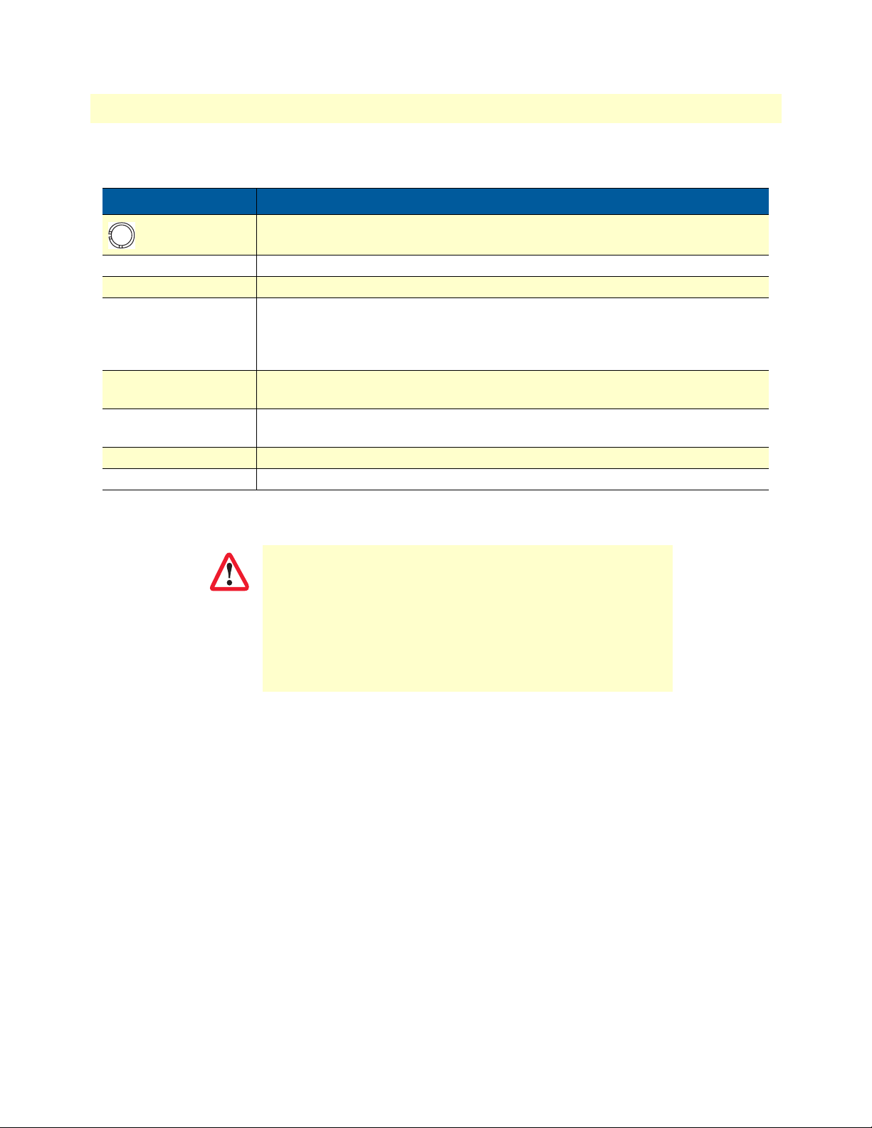
Table 1. General conventions
Convention Meaning
Garamond blue type
Garamond bold type Indicates the names of command buttons that execute an action.
< > Angle brackets indicate function and keyboard keys, such as <SHIFT>, <CTRL>,
Indicates a cross-reference hyperlink that points to a figure, graphic, table, or section heading. Clicking on the hyperlink jumps you to the reference. When you
have finished reviewing the reference, click on the Go to Previous View
button in the Adobe® Acrobat® Reader toolbar to return to your starting point.
<C>, and so on.
16
Page 17

Chapter 1 General Information
Chapter contents
Model 3101 Series Overview.................................................................................................................................18
Features ..........................................................................................................................................................18
Models ............................................................................................................................................................18
Front Panel............................................................................................................................................................19
LEDs ..............................................................................................................................................................19
Rear Panel .............................................................................................................................................................21
Ports ...............................................................................................................................................................22
17
Page 18

Model 3101 Series Getting Started Guide 1 • General Information
Model 3101 Series Overview
Patton’s Model 3101 Series ipRocketLink™ ADSL2/2+ bridge/routers are the perfect choice for users or service providers who need triple-play ready ADSL CPE with advanced routing functionality. Based on International Telecommunications Union (ITU) and American National Standard Institute (ANSI) standards
G.992.1, G.992.2, G.992.3, G.992.5 and ANSI T1.413 Issue 2, the Patton ipRocketLink bridge/routers
enable providers to deliver scalable bandwidth, up to 24 Mbps, to the most demanding voice, video and data
applications. The ipRocketLink likewise supports G.Handshaking per ITU G.994.1.
The ipRocketLink is designed specifically to be compatible with the most popular DSLAMs in the market. Just
set the units to their default mode, send them to the remote location and plug them in. The ipRocketLink will
use the ADSL-aware CAC and automatically detect the ATM PVCs and start working.
The ipRocketLink line of ADSL bridge/routers come standard with support for IPoA, PPPoA, PPPoE, and
multi-protocol encapsulation over ATM. Up to eight PVCs can be configured and ATM QoS applied via a
simple traffic class configuration. In addition to supporting standard RIPv1 and v2 routing, the ipRocketLink
can be configured with static routes. Bridging, including Spanning Tree is supported, as well as the ability to
log into standard service provider networks with PPPoE using PAP/CHAP authentication. ipRocketLink routers support many advanced firewall features including ACLs and intrusion detection with blacklisting of
offenders. Common features such as DHCP and NAT/PAT with application level gateway (ALG) also come
standard.
Features
The Model 3101 Series supports the following features:
• ADSL2/2+—Support bandwidth hungry multimedia applications up to 24 Mbps at extended distances.
• QoS Bridge/Router—Support for advanced routing with QoS and bridging including Spanning Tree and
802.1p/Q.
• Unmatched Connectivity—The 3101 comes standard with USB and WiFi interfaces and with an Ethernet
or 4-port Ethernet switch.
• Software Upgradeable—Software upgrades make it easy to keep the ipRocketLink™ in service for years.
• NetLink™ Plug-and-Play—Just plug them in and the link comes up in seconds. With support for CAC,
connection to the DSLAM is a snap.
• SNMP/HTTP—The ipRocketLink Model Series supports SNMP and HTTP/WWW-based manage-
ment.
Models
There are three different model types for the Model 3101 Series:
• 3101/1Ix – ADSL2+ modem/router with single Ethernet port
• 3101/4Ix – ADSL2+ modem/router with four Ethernet ports
• 3101/4IWUx – ADSL2+ modem/router with four Ethernet ports, WiFi, andUSB
Note
The x in the model code represents the annex type. 3101 models are
available for Annex A, Annex B, or Annex M.
Model 3101 Series Overview 18
Page 19
Model 3101 Series Getting Started Guide 1 • General Information
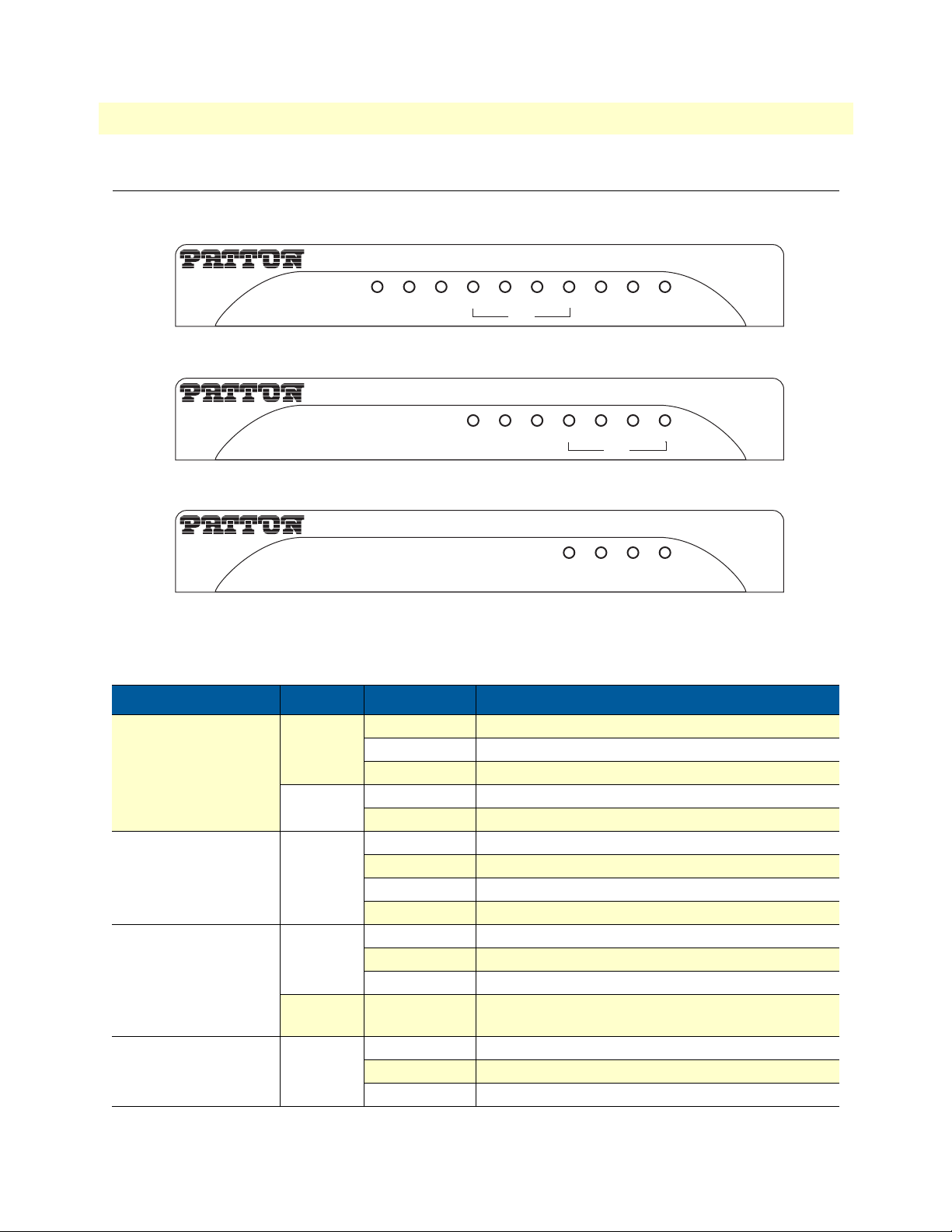
Front Panel
Model 3101/4IWU
ipRocketLink
ADSL2+ Router
Power Line Data
4 3 2 1 WLAN WPS USB
LAN
Model 3101/4I
ipRocketLink
ADSL2+ Router
Power Data Line
4321
LAN
Model 3101/1I
ipRocketLink
ADSL2+ Router
Power Line Data
Figure 1. Model 3101 Series front panels
LEDs
Table 2. LED Descriptions
LED Color Status Description
Power Green On The device is powered on and operating normally.
Blink The software is upgrading.
Off The device is powered off.
Red On The device is initiating.
Blink The software us upgrading.
Line Green On DSL link has been established.
Blink slowly No DSL link detected.
Blink quickly The DSL line is training.
Off The device is powered off.
Data Green On PPP/DHCP takes effect.
Blink slowly PPP/DHCP is negotiating.
Blink quickly Data is being transmitted.
Red On The Internet authentication fails or the device is in
bridge mode.
Ethernet (1-4) Green On The Ethernet interface is connected.
Blink Data is being transmitted through the ETH interface.
Off The Ethernet interface is disconnected.
Ethernet
Front Panel 19
Page 20

Model 3101 Series Getting Started Guide 1 • General Information
Table 2. LED Descriptions
LED Color Status Description
WLAN
(/4IWU model only)
WPS
(/4IWU model only)
USB
(/4IWU model only)
Green On WLAN is enabled.
Blink Data is being transmitted through the WiFi.
Off WLAN is disabled.
Green On Connection succeeds under WiFi Protected Setup.
Blink Negotiation is in progress under WiFi Protected
Setup.
Off WiFi Protected Setup is disabled.
Green On A 3G or USB connection has been established.
Blink Data is being transmitted.
Off No signal is detected.
Front Panel 20
Page 21
Model 3101 Series Getting Started Guide 1 • General Information
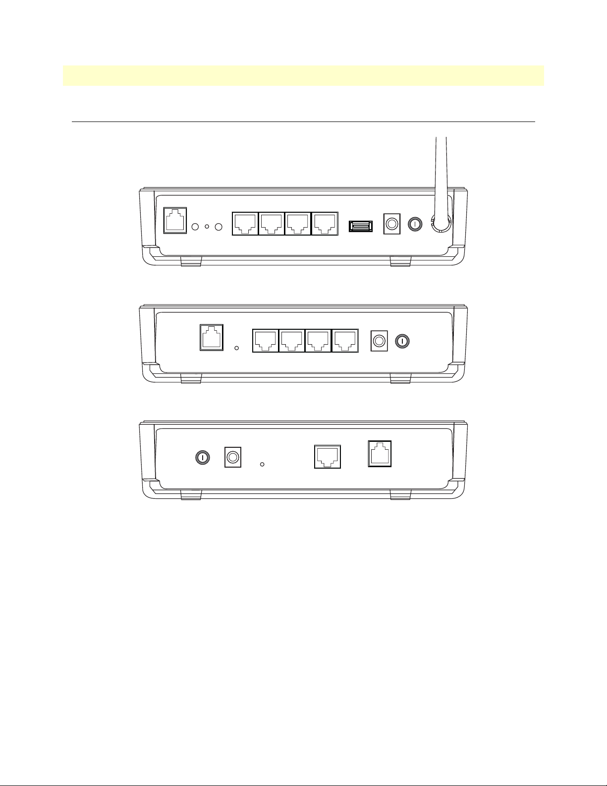
Rear Panel
Model 3101/4IWU
Reset
WLAN WPS
Line
Model 3101/4I
Line
Eth 1 Eth 2 Eth 3 Eth 4
Reset
Eth 1 Eth 2 Eth 3 Eth 4
USB Power
Power
Model 3101/1I
Power
Reset
Ethernet
Figure 2. Model 3101 rear panel
Line
Rear Panel 21
Page 22
Model 3101 Series Getting Started Guide 1 • General Information
Ports
Table 3. Port Descriptions
Port Description
Interface for connecting antennas
Line RJ-11 port for connecting to ADSL telephone line
WLAN WLAN switch for enabling/disabling the WLAN function
Reset You may need to reset the Model 3101 if you lose network connectivity or if you
can no longer communicate with the Model 3101 via the web interface.
Press the Reset button for at least 1 second and then release to restart the unit with
factory default settings.
WPS
(/4IWU model)
Ethernet (1-4) RJ-45 port for connecting the unit to an Ethernet LAN (for example, a PC or switch).
USB (/4IWU model) USB port for connecting the unit to a 3G network card or USB storage device
Power Interface for connecting the power adapter
Use this button to enable WiFi Protected Setup (WPS) Push-Button Configuration
(PBC) mode. If WPS is enabled, press this button to start negotiation of PBC mode.
The Model 3101 has four LAN ports.
IMPORTANT
Do not press the Reset button unless you want to clear the current
settings. The Reset button is in a small circular hole on the rear
panel. If you want to restore the default settings, press the Reset
button gently for 1 second with a fine needle inserted into the hole
and then release the button. The system reboots and returns to the
factory defaults.
The power specification is 12V, 1A. If the power adapter does
not match the specification, it may damage the device.
Rear Panel 22
Page 23

Chapter 2 Applications Overview
Chapter contents
Typical applications...............................................................................................................................................24
23
Page 24
Model 3101 Series Getting Started Guide 2 • Applications Overview
Typical applications
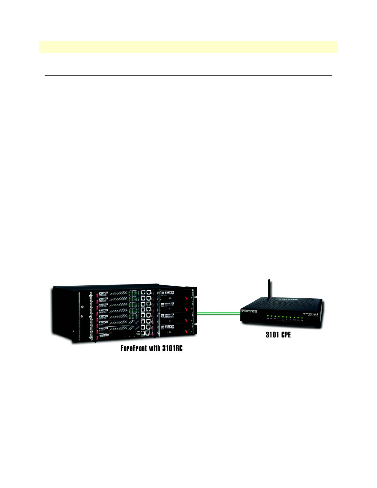
You may use the Model 3101 for the following applications:
• Home gateway
• SOHO applications
• Small enterprise applications
• Higher data rate broadband sharing
• Audio and video streaming and transfer
• PC file and application sharing
• Network and online gaming
The Model 3101excels in manageability:
• NetLinkPlug-and-play automatically facilitates remote unit configuration using standard ADSL CAC.
• Ethernet/USB/WiFi ports facilitates local management
• UPnP makes unit discovery a snap
• With SNMP and HTTP/web management, the ipRocketLink can be managed from virtually any location
in the world
• RocketLink™ bridges/routers are software upgradeable with TFTP/FTP
Figure 3. 3101 application
Typical applications 24
Page 25

Chapter 3 Installation and Initial
Configuration
Chapter contents
Installation Overview.............................................................................................................................................26
Planning the Installation........................................................................................................................................26
Location requirements ....................................................................................................................................26
Wireless operation .....................................................................................................................................26
Installing the Model 3101 .....................................................................................................................................27
Resetting the Model 3101 .....................................................................................................................................28
Configuration Overview ........................................................................................................................................28
Setting Up the 3101 for Configuration..................................................................................................................29
WAN and LAN Connections ..........................................................................................................................29
WAN ........................................................................................................................................................29
LAN ..........................................................................................................................................................29
PC Network Configuration ............................................................................................................................30
Windows XP .............................................................................................................................................30
Linux ........................................................................................................................................................30
25
Page 26

Model 3101 Series Getting Started Guide 3 • Installation and Initial Configuration
Installation Overview
The Model 3101 maintains several separate interfaces– Ethernet LAN, ADSL (WAN), and a wireless LAN
interface.
Planning the Installation
Location requirements
Place the 3101 in a location where it can be connected to the various devices as well as to a power source. The
3101 should not be located where it will be exposed to moisture or excessive heat. Make sure the cables and
power cord are placed safely out of the way so they do not create a tripping hazard. As with any electrical appliance, observe common sense safety procedures. The 3101 can be placed on a shelf or desktop. Ideally, you
should be able to see the LED indicators on the front if you need to view them for troubleshooting.
Wireless operation
Many environmental factors can affect the effective wireless function of the 3101. If this is your first time setting up a wireless network device, read and consider the points listed below. The access point can be placed on
a shelf or desktop, ideally you should be able to see the LED indicators on the front if you need to view them
for troubleshooting.
Designed to go up to 100 meters indoors and up to 300 meters outdoors, Wireless LAN lets you access your
network from anywhere you want. However, the number of walls, ceilings, or other objects that the wireless
signals must pass through can limit signal range. Typical ranges vary depending on the types of materials and
background RF noise in your home or business.
Installation Overview 26
Page 27

Model 3101 Series Getting Started Guide 3 • Installation and Initial Configuration
r
c
Installing the Model 3101
Do not work on the system or connect or disconnect cables during periods of
lightning activity.
WARNING
Do not place any objects on top of or near the vent holes on the Model 3101
case.
WARNING
The interconnecting cables must be acceptable for external use
and must be rated for the proper application with respect to volt-
CAUTION
To set up the Model 3101 (Figure 4):
1. Connect the Line port of the 3101 using a straight-through RJ-11 cable.
age, current, anticipated temperature, flammability, and
mechanical serviceability.
2. Connect an Ethernet port of the 3101 to the network card of the PC via an Ethernet cable.
3. Plug one end of the power adapter to the wall outlet and connect the other end to the Power port on the
3101.
Figure 4 displays the installation diagram for connecting the 3101.
Telephone
Phone
Jack
Telephone Line
PHONE
LINE
Line WLAN WPS
MODEM
Splitter
Telephone Lin
Reset
Eth 1 Eth 2 Eth 3 Eth 4
Ethernet Line
PC
USB Power
Powe
Ja
Figure 4. Model 3101 installation diagram (/4IWU model shown)
Installing the Model 3101 27
Page 28

Model 3101 Series Getting Started Guide 3 • Installation and Initial Configuration
Resetting the Model 3101
You may press the Reset button while the unit is on to reset to the original factory settings. Use a ballpoint pen
or paper clip to gently push the reset button. Remember that this will delete any settings stored in flash memory including user account information and LAN IP settings.
The device settings will be restored to the factory default IP address 192.168.1.1 and the subnet mask
255.255.255.0. The default management username is admin and the default password is admin.
Configuration Overview
The Model 3101 Series leverages a wide range of compelling broadband-based applications and services and
includes an operating system, drivers and remote management capabilities. The 3101delivers a set of highly
integrated solutions, required for the home and small of company, such as:
–IP Routing and Bridging
– Asynchronous Transfer Mode (ATM) and Digital Subscriber Line (DSL) support
– Point-to-Point Protocol (PPP)
– Network/Port Address Translation (NAT/PAT)
– Quality of Service (QoS)
– Wireless LAN Security: WPA, 802.1x, RADIUS client (/4IWU model)
– Virtual Private Network (VPN): IPSec
– Secure Socket Layer Virtual Private Network (SSL VPN)
– Universal Plug-and-Play
– File Server for Network Attached Storage (NAS) devices
– Print Server
–Web Filtering
– Management and Control: Web-based Management (WBM), Simple Network Management Proto-
col(SNMP), Command Line Interface (CLI), TR-069WAN Management Protocol, TR-064-LAN-Side
DSL CPE Configuration
– Remote Update
– System Statistics and Monitoring
Resetting the Model 3101 28
Page 29
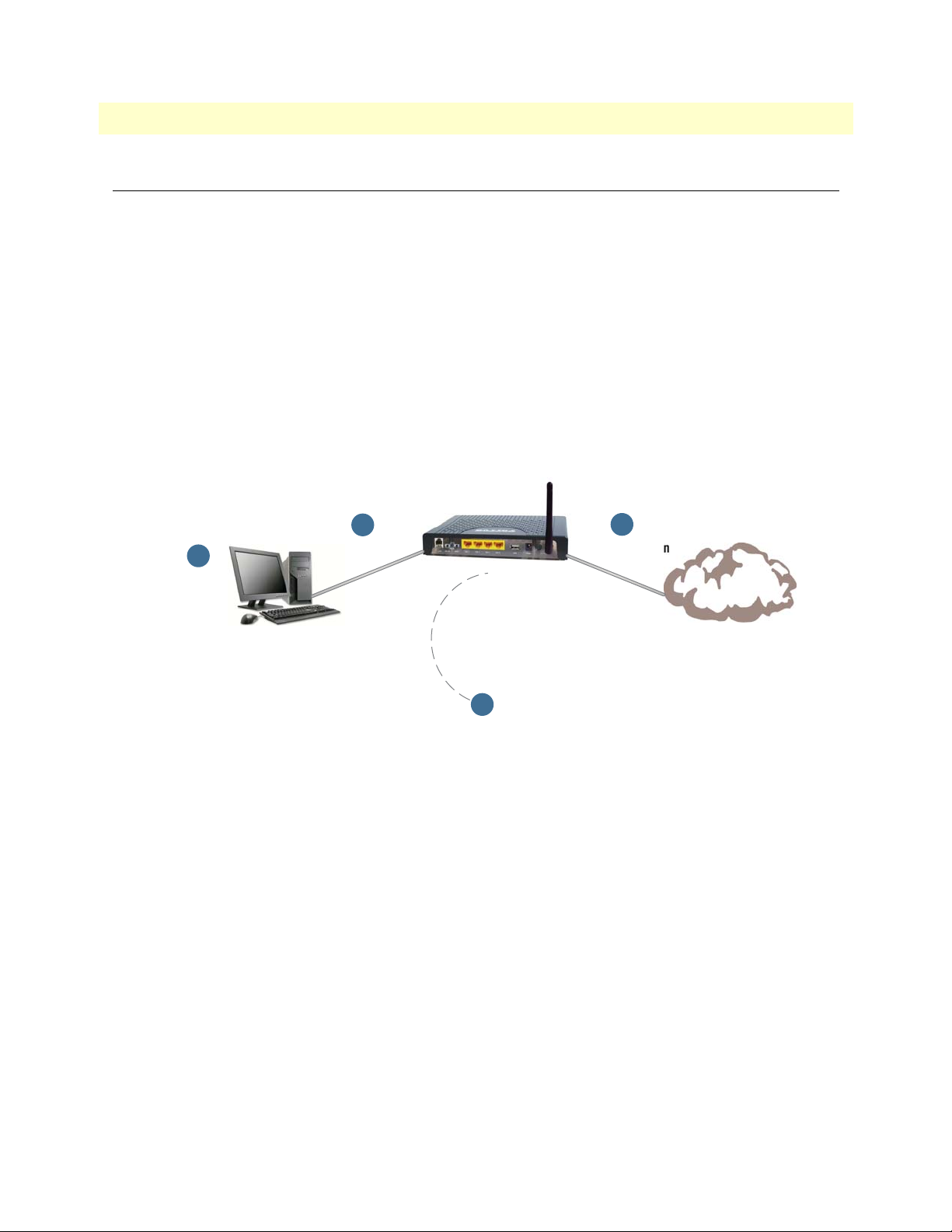
Model 3101 Series Getting Started Guide 3 • Installation and Initial Configuration
Setting Up the 3101 for Configuration
Connecting your computer or home network to the 3101 is a simple procedure, varying slightly depending on
your operating system. This chapter will help you to seamlessly integrate 3101 with your computer or home
network. The Windows default network settings dictate that in most cases the setup procedure described below
will be unnecessary. For example, the default DHCP setting in Windows 2000 is 'client', requiring no further
modification.
However, it is advised to follow the setup procedure described below to verify that all communication parameters are valid and that the physical cable connections are correct. The setup procedure consists of three consecutive configuration stages:
• “WAN and LAN Connections” on page 29
• “PC Network Configuration” on page 30
• “Device Access and Information” on page 31
1
WAN Connection
Internet
2
PC Network
Configuration
1
LAN Connection
DSL
3
DSL Quick Setup
Figure 5. Typical setup diagram
WAN and LAN Connections
WAN
To connect the 3101 to the Internet, use a straight-through RJ-11 cable to connect the Line port on the unit to
a DSL wall socket.
LAN
Your computer can connect to the 3101 using an Ethernet port on the unit (all models) or the wireless antenna
(/4IWU model). Use an Ethernet cable to connect an Ethernet port on the unit to a PC network card.
Setting Up the 3101 for Configuration 29
Page 30
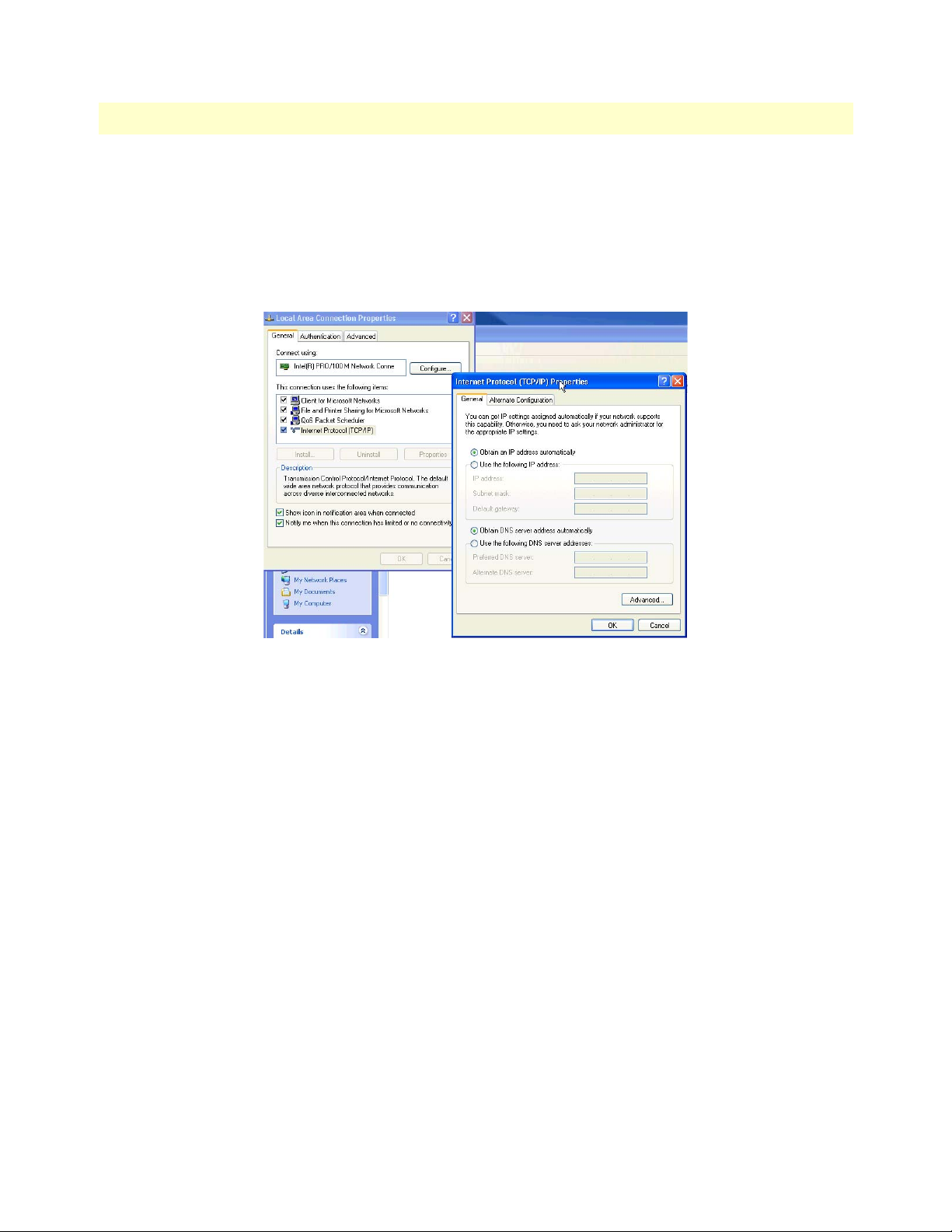
Model 3101 Series Getting Started Guide 3 • Installation and Initial Configuration
PC Network Configuration
Each network interface on the PC should either be configured with a statically defined IP address and DNS
address, or should be instructed to automatically obtain an IP address using the Network DHCP server. 3101
provides a DHCP server on its LAN and it is recommended to configure your LAN to obtain its IP and DNS
server IP automatically. This configuration principle is identical but performed differently on each operating
system. Figure 6 displays the TCP/IP Properties dialog box as it appears in WTCP/IP configuration instruc-
tions for all supported operating systems.
Figure 6. TCP/IP Settings (Windows XP OS)
Windows XP
1. From the Start menu, select Control Panel > Network Connections.
2. Right-click on the Ethernet connection icon and select Properties. The Local Area Connection Properties
window displays.
3. Click on the General tab and select Internet Protocol (TCP/IP). Click Properties. The Internet Protocol
(TCP/IP) Properties window displays (Figure 6).
4. Select the Obtain an IP address automatically radio button, and select the Obtain DNS server address
automatically radio button. Click OK to save the settings.
Linux
1. Log into the system as a super-user, by entering “su” at the prompt.
2. Type “ifconfig” to display the network devices and allocated IP addresses.
3. Type “pump -i <dev>”, where <dev> is the network device name.
4. Type “ifconfig” again to view the newly allocated IP address.
5. Make sure no firewall is active on device <dev>.
Setting Up the 3101 for Configuration 30
Page 31

Chapter 4 Device Access and Information
Chapter contents
Overview ...............................................................................................................................................................32
Logging In.............................................................................................................................................................32
Viewing Device Information .................................................................................................................................33
Summary ........................................................................................................................................................33
WAN Interface ...............................................................................................................................................33
Statistics ..........................................................................................................................................................33
LAN ..........................................................................................................................................................33
WAN ........................................................................................................................................................34
xTM .........................................................................................................................................................34
xDSL ........................................................................................................................................................35
xDSL BER Test................................................................................................................................... 35
Route ..............................................................................................................................................................36
ARP ................................................................................................................................................................36
DHCP ............................................................................................................................................................36
31
Page 32

Model 3101 Series Getting Started Guide 4 • Device Access and Information
Overview
This chapter describes how to access the Model 3101 Series Web Management Interface (WMI), which allows
you to configure and control all of the 3101 features and system parameters, using a user-friendly graphical
interface. This user-friendly approach is also implemented in the WMI's documentation structure, which is
based directly on the WMI's structure.
See the following sections for information on managing the 3101 through the WMI:
• “Logging In” on page 32 for accessing the WMI
• “Viewing Device Information” on page 33 for viewing device statistics
• Chapter 5, “Advanced Configuration” on page 37 for setting up advanced features
• Chapter 7, “System Management” on page 105 for testing the DSL line and managing system settings
• Chapter 6, “Wireless Configuration” on page 90 for configuring the wireless and USB storage features of
the /4IWU version of the Model 3101
Figure 7. WMI home page
Logging In
To log into the 3101’s WMI for the first time:
1. Launch a Web browser on your computer.
2. Browse to “http://192.168.1.1” (the 3101’s default IP address).The login page displays.
3. Enter a username and password. The default superuser username and password are both admin. The
default operator/common username and password are both user. It is recommended to change these default
values after logging into the 3101 for the first time.
4. Click OK to login, or click Cancel to exit the login interface.
After logging into the 3101 with the superuser username, you can query, configure, modify all configurations.
You may need to reboot the 3101 for some configurations to take effect.
Overview 32
Page 33

Model 3101 Series Getting Started Guide 4 • Device Access and Information
Viewing Device Information
The Device Info section of the WMI provides an overview of the unit’s interface statistics, connection status, and routes.
Summary
Click Device Info > Summary (Figure 7 on page 32) to view the unit’s software versions and DSL
status: Board ID, Software Version, and the information of your WAN connection such as the
upstream rate and the LAN IPv4 address.
WAN Inter face
Click Device Info > WAN (Figure 8) to view the WAN interface settings, such as the connection status, IPv4
address, and connected time.
Figure 8. WMI: WAN Interface Info
Statistics
The Device Info > Statistics menu provides LAN, WAN, ATM, and ADSL information.
LAN
In the Device Info > Statistics menu, click LAN (Figure 9) to view the LAN interface statistics. You can query
information on packets received on the Ethernet and Wireless interfaces (where applicable). Click Reset Sta-
tistics to return the values to zero.
Figure 9. WMI: LAN Statistics
Viewing Device Information 33
Page 34

Model 3101 Series Getting Started Guide 4 • Device Access and Information
WAN
In the Device Info > Statistics menu, click WAN (Figure 10) to view the WAN interface statistics. You can
query information on packets recevied on the WAN interfaces. Click Reset Statistics to return the values to
zero.
Figure 10. WMI: WAN Statistics
xTM
In the Device Info > Statistics menu, click xTM (Figure 11) to view the ATM interface statistics. You can
query information on packets recevied on the xTM interfaces. Click Reset Statistics to return the values to
zero.
Figure 11. WMI: ATM Statistics
Viewing Device Information 34
Page 35

Model 3101 Series Getting Started Guide 4 • Device Access and Information
xDSL
In the Device Info > Statistics menu, click xDSL (Figure 12) to view the DSL interface statistics.
Figure 12. WMI: xDSL Statistics
xDSL BER Test. Click xDSL BER Test on the xDSL Statistics page to run a Bit Error Rate (BER) Test on
the DSL line. Select a time from the Tested Time (sec) drop-down menu and click Start to begin the test. The
Tested Time choices are: 1, 5, 10, 20, 60, 120, 180, 240, 300, and 360.
Figure 13. WMI: ADSL BER Test
Note
If the Error Ratio reaches up to “e-5”, you will not be able to access
the Internet.
Viewing Device Information 35
Page 36

Model 3101 Series Getting Started Guide 4 • Device Access and Information
Route
Click Device Info > Route (Figure 14) to view route table information.
Figure 14. WMI: Route Info
ARP
Click Device Info > ARP (Figure 15) to view MAC and IP information of equipment attached to the 3101.
Figure 15. WMI: ARP Info
DHCP
Click Device Info > DHCP (Figure 15) to view the host name, the IP address assigned by the DHCP server,
the MAC address which is corresponding to the IP address, and the DHCP lease time.
Figure 16. WMI: DHCP Info
Viewing Device Information 36
Page 37

Chapter 5 Advanced Configuration
Chapter contents
Overview ...............................................................................................................................................................39
Layer2 Interface Setup ...........................................................................................................................................39
WAN Service Setup...............................................................................................................................................40
PPP over Ethernet (PPPoE) ............................................................................................................................41
MAC Encapsulation Routing (MER) (IPoE) ..................................................................................................45
PPP over ATM (PPPoA) .................................................................................................................................48
IP over ATM (IPoA) .......................................................................................................................................52
Bridging ..........................................................................................................................................................55
3G WAN Service Setup.........................................................................................................................................56
LAN Setup ............................................................................................................................................................59
Configuring the private IP address for the 3101 ..............................................................................................59
Enabling IGMP Snooping ..............................................................................................................................60
Enabling the LAN Side Firewall ......................................................................................................................60
Configuring the DHCP Server .......................................................................................................................60
Editing the DHCP Option .............................................................................................................................61
Editing the DHCP Option 60 ........................................................................................................................61
Configuring the DHCP Static IP Lease List ....................................................................................................61
Configuring the second IP address and subnet mask for a LAN interface ........................................................62
Setting up IPv6 LAN Auto Configuration ......................................................................................................62
Network Address Translation (NAT) Setup ..........................................................................................................63
Virtual Servers .................................................................................................................................................63
Port Triggering ...............................................................................................................................................64
DMZ Host .....................................................................................................................................................66
Multi NAT .....................................................................................................................................................66
Security Setup .......................................................................................................................................................67
IP Filtering ......................................................................................................................................................67
Outgoing ..................................................................................................................................................67
Incoming ..................................................................................................................................................68
MAC Filtering ................................................................................................................................................69
Parental Control Setup..........................................................................................................................................71
Time Restriction .............................................................................................................................................71
URL Filter ......................................................................................................................................................72
Quality of Service (QoS) Setup..............................................................................................................................73
Queue Management .......................................................................................................................................73
Queue Configuration ......................................................................................................................................74
QoS Classification ..........................................................................................................................................75
Routing Setup .......................................................................................................................................................76
Default Gateway .............................................................................................................................................77
Static Route ....................................................................................................................................................77
37
Page 38

Model 3101 Series Getting Started Guide 5 • Advanced Configuration
Policy Routing ................................................................................................................................................78
DSL Setup.............................................................................................................................................................78
Universal Plug & Play (UPnP) Setup ....................................................................................................................79
Domain Name System (DNS) Proxy Setup...........................................................................................................79
Print Server Setup..................................................................................................................................................79
Packet Acceleration Setup......................................................................................................................................80
Storage Service Setup.............................................................................................................................................80
Storage Device Info .........................................................................................................................................80
User Accounts .................................................................................................................................................80
Interface Grouping Setup ......................................................................................................................................81
IPSec Setup ...........................................................................................................................................................83
Certificate Setup....................................................................................................................................................84
Local Certificates ............................................................................................................................................84
Create Certificate Request .........................................................................................................................84
Import Certificate .....................................................................................................................................86
Trusted CA Certificates ..................................................................................................................................86
Power Management...............................................................................................................................................87
Multicast Setup .....................................................................................................................................................88
38
Page 39

Model 3101 Series Getting Started Guide 5 • Advanced Configuration
Overview
The Advanced Setup section of the WMI allows you to configure features (see figure 17) for the 3101.
Figure 17. Advanced Setup Menu
Layer2 Interface Setup
Click Advanced Setup > Layer2 Interface > ATM Interface (Figure 21) to configure, modify, and remove
DSL ATM interfaces.
Figure 18. WMI: DSL ATM Interface Configuration
In the main DSL ATM interface list, you can click Add to configure a new ATM PVC identifier.
Figure 19. WMI: ATM PVC Configuration
Overview 39
Page 40

Model 3101 Series Getting Started Guide 5 • Advanced Configuration
On the ATM PVC Configuration page, you can set the VPI and VCI values, elect the DSL latency, link type
(EoA is for PPPoE, IPoE, and Bridge.), connection mode, encapsulation mode, service category, and IP QoS
scheduler algorithm.
• VPI (Virtual Path Identifier): The virtual path between two points in an ATM network, and its valid
value is from 0 to 255.
• VCI (Virtual Channel Identifier): The virtual channel between two points in an ATM network, ranging
from 32 to 65535 (1 to 31 are reserved for known protocols).
• Select DSL Latency: You may select Path0 and Path1.
• Select DSL Link Type: You may select EoA (for PPPoE, IPoE, and Bridge), PPoA or IPoA.
• Select Connection Mode: You may select the Default Mode or the VLAN MUX Mode.
• Encapsulation Mode: You may select LLC/SNAP-BRIDGING or VC/MUX in the drop-down list.
• Service Category: You may select UBR Without PCR, UBR With PCR, UBR on Realtime VBR, or Realtime
VBR in the drop-down list.
• Select IP QoS Scheduler Algorithm: You may select Strict Priority and Weighted Fair Queuing.
Note
QoS cannot be set for CBR and Realtime VBR.
Click the Apply/Save button to enable the new settings to take effect (figure 20).
Figure 20. WMI: DSL ATM Interface Configuration
To delete an interface, select the checkbox for that interface and click Remove.
WAN Service Setup
Click Advanced Setup > WAN Service (Figure 21) to configure, modify, and remove a WAN service.
Figure 21. WMI: WAN Service Configuration
In the main WAN service list, you can click Add to configure a new WAN service, click Edit to modify an
existing WAN connection, or select the checkbox for a connection and click Remove to delete an existing
WAN connection.Refer to the following sections to configure different types of WAN connections.
WAN Service Setup 40
Page 41

Model 3101 Series Getting Started Guide 5 • Advanced Configuration
• “PPP over Ethernet (PPPoE)” on page 41
• “MAC Encapsulation Routing (MER) (IPoE)” on page 45
• “PPP over Ethernet (PPPoE)” on page 41
• “IP over ATM (IPoA)” on page 52
• “Bridging” on page 55
PPP over Ethernet (PPPoE)
To create a new PPPoE connection:
1. Click Add from the main WAN service page to configure a new connection. (Before you can add a new
PPPoE service, make sure that you have created a proper ATM PVC configuration. See figure 19 on
page 39). The following page displays. Click Next to continue.
Figure 22. WMI: Select Layer2 Interface
2. On the Connection Type page (Figure 23), select the radio button for PPP over Ethernet (PPPoE). Click
Next to continue.
Figure 23. WMI: PPPoE Connection Type
WAN Service Setup 41
Page 42

Model 3101 Series Getting Started Guide 5 • Advanced Configuration
3. On the PPP Username and Password page, provide information for the PPP username, password, service
name, and authentication method.
Figure 24. WMI: PPP Information
– PPP Username: The valid username provided by your ISP.
– PPP Password: The valid password provided by your ISP.
– PPPoE Service Name: Enter the service name provided by your ISP. If the ISP does not provide a ser-
vice name, do not enter any information.
– Authentication Method: Select from AUTO, PAP, CHAP, MSCHAP. (Default = AUTO)
– Enable Fullcone NAT: With NAT, all requests from the same internal IP address and port are mapped
to the same external IP address and port. Furthermore, any external host can send a packet to the internal host, by sending a packet to the mapped external address.
– Dial on demand (with idle timeout timer): If enabled, enter the Idle Timeout value in minutes. If the
3101 doesn’t detect the flow continuously within the allotted time, the unit will automatically disconnect the PPPoE connection. Once it detects the flow (such as access to a webpage), the 3101 will restart
the PPPoE connection. If disabled, the 3101 will perform PPPoE dial-up all the time. Unless the 3101 is
powered off and DSLAM or uplink equipment are operating abnormally, the PPPoA connnection will
stay up.
– PPP IP Extension: Enable this option if you want to configure a DMZ Host. If enabled, the WAN IP
address obtained by the 3101 through built-in dial-up can be directly assigned to the PC connected to
the 3101 (at this time, the 3101 has only one PC). If disabled, the 3101 obtains the WAN IP address.
– Use Static IPv4 Address: If enabled, the 3101 uses this IP as the WAN IP address. If disabled, the 3101
obtains an IP address assigned through uplink equipment.
WAN Service Setup 42
Page 43

Model 3101 Series Getting Started Guide 5 • Advanced Configuration
– Use Static IPv6 Address: If enabled, the 3101 uses this IP as the WAN IP address. If disabled, the 3101
obtains an IP address assigned through uplink equipment.
– Enable IPv6 Unnumbered Model: Enable or disable this function.
– Enable PPP Debug Mode: Enable or disable this function.
– Bridge PPPoE Frames Between WAN and Local Ports: Enable or disable this function.
– Enable IGMP Multicast Proxy: Enable this function if you want PPPoE mode to support IPTV.
– Enable MLD Multicast Proxy: Enable or disable this function.
Click Next to continue.
4. On the Routing-Default Gateway page (Figure 25), select a preferred WAN interface as the system default
gateway. Click Next to continue.
Figure 25. WMI: Routing - Default Gateway
WAN Service Setup 43
Page 44

Model 3101 Series Getting Started Guide 5 • Advanced Configuration
5. On the DNS Configuration page (Figure 26) you may obtain the DNS server addresses from the selected
WAN interface or manually enter the static DNS server addresses. If only a PVC with IPoA or static MER
protocol is configured, you must manually enter the static DNS server addresses. Click Next to continue.
Figure 26. WMI: DNS Server Configuration
6. The final connection configuration page (Figure 27) shows an summary of the PPPoE connection. Click
Save to keep your settings. You will need to reboot the unit to activate this WAN service.
Figure 27. WMI: PPPoE Connection Summary
WAN Service Setup 44
Page 45

Model 3101 Series Getting Started Guide 5 • Advanced Configuration
MAC Encapsulation Routing (MER) (IPoE)
To create a new MER WAN service:
1. Click Add from the main WAN service page to configure a new connection. (Before you can add a new
PPPoE service, make sure that you have created a proper ATM PVC configuration. See figure 19 on
page 39). The following page displays. Click Next to continue.
Figure 28. WMI: Select Layer2 Interface
2. On the Connection Type page (Figure 23), select the radio button for IP over Ethernet (IPoE). Click
Next to continue.
Figure 29. WMI: IPoE Connection Type
3. On the WAN IP Settings page (Figure 30 on page 46), you may may select obtain an IP address automat-
ically or manually enter the IP address provided by your ISP. If you enable IPv6 for this WAN service, you
should also enter the next-hop IPV6 address. Click Next to continue.
Note
If selecting Obtain an IP address automatically, DHCP will be
enabled for PVC in MER mode.
If selecting Use the following Static IP address, enter the WAN IP
address, subnet mask and gateway IP address.
WAN Service Setup 45
Page 46

Model 3101 Series Getting Started Guide 5 • Advanced Configuration
Figure 30. WMI: WAN IP Settings
4. On the Network Address Translation Settings page (Figure 31), you may modify NAT Settings and select
to enable IGMP Multicast.
– Enable NAT: Select to enable the NAT functions of the 3101. If you do not enable NAT, you must add
a route on the uplink equipment; otherwise, the access to the Internet will fail. It is recommended to
enable NAT.
– Enable Firewall: Enable/disable IP filtering.
– Enable IGMP Multicast: Enable IGMP if you need MER mode to support IPTV.
Click Next to continue.
Figure 31. WMI: NAT Settings
WAN Service Setup 46
Page 47

Model 3101 Series Getting Started Guide 5 • Advanced Configuration
5. On the Routing-Default Gateway page (Figure 25), select a preferred WAN interface as the system default
gateway. Click Next to continue.
Figure 32. WMI: Routing - Default Gateway
6. On the DNS Configuration page (Figure 26) you may obtain the DNS server addresses from the selected
WAN interface or manually enter the static DNS server addresses. If only a PVC with IPoA or static MER
protocol is configured, you must manually enter the static DNS server addresses. Click Next to continue.
Figure 33. WMI: DNS Server Configuration
WAN Service Setup 47
Page 48

Model 3101 Series Getting Started Guide 5 • Advanced Configuration
7. The final connection configuration page (Figure 34) shows an summary of the IPoE settings. Click Save to
keep your settings. You will need to reboot the unit to activate this WAN service.
Figure 34. WMI: MER (IPoE) Connection Summary
PPP over ATM (PPPoA)
To create a new PPPoA connection:
1. Click Advanced Setup > Layer2 Interface > ATM Interface to configure, modify, and remove DSL ATM
interfaces. In the main DSL ATM interface list, you can click Add to configure a new ATM PVC identifier for PPPoA mode.
Figure 35. WMI: ATM PVC Configuration
2. On the ATM PVC Configuration page (Figure 35), select the DSL link type for PPoA and select VC/
MUX as the encapsulation mode (according to the uplink equipment). Click the Apply/Save button for
the settings to take effect. The DSL ATM Interface list displays.
WAN Service Setup 48
Page 49

Model 3101 Series Getting Started Guide 5 • Advanced Configuration
3. Click Add from the main WAN service page to configure a new connection. The following page displays.
Click Next to continue.
Figure 36. WMI: Select Layer2 Interface
4. On the Service Configuration page (Figure 23), modify the service description. Click Next to continue.
Figure 37. WMI: PPPoA Service Description
5. On the PPP Username and Password page, provide information for the PPP username, password, service
name, and authentication method.
Figure 38. WMI: PPP Information
WAN Service Setup 49
Page 50

Model 3101 Series Getting Started Guide 5 • Advanced Configuration
– PPP Username: The valid username provided by your ISP.
– PPP Password: The valid password provided by your ISP.
– Authentication Method: Select from AUTO, PAP, CHAP, MSCHAP. (Default = AUTO)
– Enable Fullcone NAT: With NAT, all requests from the same internal IP address and port are mapped
to the same external IP address and port. Furthermore, any external host can send a packet to the internal host, by sending a packet to the mapped external address.
– Dial on demand (with idle timeout timer): If enabled, enter the Idle Timeout value in minutes. If the
3101 doesn’t detect the flow continuously within the allotted time, the unit will automatically disconnect the PPPoA connection. Once it detects the flow (such as access to a webpage), the 3101 will restart
the PPPoA connection. If disabled, the 3101 will perform PPPoA dial-up all the time. Unless the 3101
is powered off and DSLAM or uplink equipment are operating abnormally, the PPPoA connnection will
stay up.
– Use Static IPv4 Address: If enabled, the 3101 uses this IP as the WAN IP address. If disabled, the 3101
obtains an IP address assigned through uplink equipment.
– Enable PPP Debug Mode: Enable or disable this function.
– Enable IGMP Multicast Proxy: Enable this function if you want PPPoA mode to support IPTV.
Click Next to continue.
6. On the Routing-Default Gateway page (Figure 25), select a preferred WAN interface as the system default
gateway. Click Next to continue.
Figure 39. WMI: Routing - Default Gateway
WAN Service Setup 50
Page 51

Model 3101 Series Getting Started Guide 5 • Advanced Configuration
7. On the DNS Configuration page (Figure 26) you may obtain the DNS server addresses from the selected
WAN interface or manually enter the static DNS server addresses. If only a PVC with IPoA or static MER
protocol is configured, you must manually enter the static DNS server addresses. Click Next to continue.
Figure 40. WMI: DNS Server Configuration
8. The final connection configuration page (Figure 27) shows an summary of the PPPoA connection. Click
Save to keep your settings. You will need to reboot the unit to activate this WAN service.
Figure 41. WMI: PPPoA Connection Summary
WAN Service Setup 51
Page 52

Model 3101 Series Getting Started Guide 5 • Advanced Configuration
IP over ATM (IPoA)
To create a new IPoA connection:
1. Click Advanced Setup > Layer2 Interface > ATM Interface to configure, modify, and remove DSL ATM
interfaces. In the main DSL ATM interface list, you can click Add to configure a new ATM PVC identifier for PPPoA mode.
Figure 42. WMI: ATM PVC Configuration
2. On the ATM PVC Configuration page (Figure 42), select the DSL link type for IPoA and select LLC/
SNAP-ROUTING as the encapsulation mode (according to the uplink equipment). Click the Apply/Save
button for the settings to take effect. The DSL ATM Interface list displays.
3. Click Add from the main WAN service page to configure a new connection. The following page displays.
Click Next to continue.
Figure 43. WMI: Select Layer2 Interface
WAN Service Setup 52
Page 53

Model 3101 Series Getting Started Guide 5 • Advanced Configuration
4. On the Service Configuration page (Figure 44), modify the service description. Click Next to continue.
Figure 44. WMI: IPoA Service Description
5. On the WAN IP Settings page, enter the WAN IP address and the WAN subnet mask provided by your
ISP. Click Next to continue.
Figure 45. WMI: WAN IP Settings
6. On the Network Address Translation Settings page (Figure 46), you may modify NAT Settings and select
to enable IGMP Multicast.
– Enable NAT: Select to enable the NAT functions of the 3101. If you do not enable NAT, you must add
a route on the uplink equipment; otherwise, the access to the Internet will fail. It is recommended to
enable NAT.
– Enable Firewall: Enable/disable IP filtering.
– Enable IGMP Multicast: Enable IGMP if you need MER mode to support IPTV.
Click Next to continue.
Figure 46. WMI: NAT Settings
WAN Service Setup 53
Page 54

Model 3101 Series Getting Started Guide 5 • Advanced Configuration
7. On the Routing-Default Gateway page (Figure 47), select a preferred WAN interface as the system default
gateway. Click Next to continue.
Figure 47. WMI: Routing - Default Gateway
8. On the DNS Configuration page (Figure 48) you should use a static DNS IP address for IPoA mode.
Select the proper DNS server interface and enter the primary DNS server and the secondary DNS server.
Click Next to continue.
Figure 48. WMI: DNS Server Configuration
WAN Service Setup 54
Page 55

Model 3101 Series Getting Started Guide 5 • Advanced Configuration
9. The final connection configuration page (Figure 49) shows an summary of the IPoA connection. Click
Save to keep your settings. You will need to reboot the unit to activate this WAN service.
Figure 49. WMI: IPoA Connection Summary
Bridging
To create a new bridge connection:
1. Click Add from the main WAN service page to configure a new connection. (Before you can add a new
PPPoE service, make sure that you have created a proper ATM PVC configuration. See figure 19 on
page 39). The following page displays. Click Next to continue.
Figure 50. WMI: Select Layer2 Interface
WAN Service Setup 55
Page 56

Model 3101 Series Getting Started Guide 5 • Advanced Configuration
2. On the Connection Type page (Figure 51), select the radio button for Bridging and select LLC/SNAP-
ROUTING as the Encapsulation Mode. Click Next to continue.
Figure 51. WMI: Bridging Connection Type
3. The final connection configuration page (Figure 52) shows an summary of the Bridging connection. Click
Save to keep your settings. You will need to reboot the unit to activate this WAN service.
Figure 52. WMI: Bridging Connection Summary
3G WAN Service Setup
Click Advanced Setup > 3G WAN Service (Figure 53) to configure a 3G connection.
Figure 53. WMI: 3G Connection Setup
If you want to access the Internet through a 3G connection, a 3G network card is required. Connect the 3G
network card to the USB interface of the 3101.
3G WAN Service Setup 56
Page 57

Model 3101 Series Getting Started Guide 5 • Advanced Configuration
• Information: Click this button to display the information of the 3G network card.
• Upload Driver: For an unsupported USB dongle, click this button to upload the new driver for supporting
the USB. The driver is a text file.
Click Pin Manage, and the following page displays.
Figure 54. WMI: 3G Pin Configuration
• Enable PIN protect: If enabled, you need to enter the PIN code when rebooting or inserting the USB.
• Unlock with PIN code: If disabled, you need to enter PIN code when using 3G.
• Unlock with PUK & PIN: If disabled, you need to enter PUK code when failing to enter the PIN code for
3 times.
• Change PIN code: Select this radio button to modify the PIN code.
After proper settings, click Submit for the new settings to take effect.
Click Add in the WAN Service For 3G Moblie Setup to display the following page.
Figure 55. WMI: 3G USB Modem Setup
3G WAN Service Setup 57
Page 58

Model 3101 Series Getting Started Guide 5 • Advanced Configuration
In the 3G WAN Service page, you may configure the settings of the 3G USB modem.
• Enable USB Modem: f you want to access the Internet through the 3G network card, you must enable the
USB modem.
• User Name: Username provided by your 3G ISP.
• Password: Password provided by your 3G ISP.
• Authentication Method: Select a proper authentication method in the drop- down list. You can select
Auto, PAP, CHAP, or MSCHAP.
• APN: APN (Access Point Name) is used to identify the service type. Enter the APN provided by your 3G
ISP.
• Dial Number: Enter the dial number provided by your 3G ISP.
• Idle time (in sec.): If no traffic for the preset time, the 3G will disconnect automatically.
• Net Select: Select the 3G network that is available.You may select EVDO, WCDMA, CDMA2000, TD-
SCDMA, GSM, or Auto.
• Dial on demand: Within the preset minutes, if the modem does not detect the flow of the user continu-
ously, the modem automatically stops the 3G connection. Once it detects the flow (like access to a
webpage), the modem restarts the 3G dialup.
• Dial Delay (in sec.): The 3G delays dial after the DSL is disconnected.
• Default WAN Connection Select: You can select DSL or 3G from the drop-down list.
• WAN back mechanism: The 3G connection is backup for the DSL connection.
- DSL: If the DSL is disconnected, the 3G starts to dial.
- IP connectivity: If the system fails to ping the specified IP address, the 3G starts to dial.
Click the Apply/Save button to save the settings.You may also click the Auto setting button to automatically
configure the 3G connection. After clicking the Apply/Save button, the following page displays.
Figure 56. WMI: Adding a 3G WAN Service
If the 3G network card is installed, you may click the button on the ctioncolumn to establish or disconnect the
3G connection.
Note
When there is no DSL WAN connection, insert the 3G network
card, and then system will perform dial-up automatically. If the DSL
WAN connection and the 3G connection coexist, the DSL WAN
3G WAN Service Setup 58
Page 59

Model 3101 Series Getting Started Guide 5 • Advanced Configuration
connection takes priority over the 3G connection. When the DSL
WAN connection starts to perform dial-up, the 3G connection will
be disconnected. If the DSL WAN connection has established, you
may manually perform 3G dial-up, and then the DSL WAN connection will be disconnected.
LAN Setup
Click Advanced Setup > LAN (Figure 57) to define an IP address for the 3101 and configure the DHCP
server.
Figure 57. WMI: LAN Interface Configuration
Configuring the private IP address for the 3101
On the LAN Setup page (Figure 57), you can change the device's IP address. The preset IP address is
192.168.1.1. This is the private IP address of the 3101 and the address that the device can be reached on in the
local network. The IP address under which the 3101 can be reached from outside the LAN is assigned by the
Internet Service Provider.
If you want to assign a different IP address to the 3101, enter it in the IP Address field. Adjust the Subnet
Mask if necessary. You should use an address from a block that is reserved for private use (192.168.1.1-
192.168.255.254).
LAN Setup 59
Page 60

Model 3101 Series Getting Started Guide 5 • Advanced Configuration
Note
New settings can only be made after the 3101 has been rebooted. If
necessary, reconfigure the IP address on your PC (including one that
is statically assigned) so that it matches the new configuration.
Enabling IGMP Snooping
IGMP snooping enables the router to forward multicast traffic intelligently, instead of flooding all ports in the
VLAN. With IGMP snooping, the router listens to IGMP membership reports, queries and leave messages to
identify the switch ports that are members of multicast groups. Multicast traffic will only be forwarded to ports
identified as members of the specific multicast group or groups.
Select the checkbox to Enable IGMP Snooping (Figure 58) on the LAN Setup page (Figure 57 on page 59).
Figure 58. WMI: IGMP Snooping
Enabling the LAN Side Firewall
The firewall can prevent unexpected traffic on the Internet from your host to the LAN. Select the checkbox to
Enable LAN Side Firewall on the LAN Setup page (Figure 57 on page 59).
Configuring the DHCP Server
The Model 3101 has a DHCP server for which the factory setting is active. Consequently, the IP addresses of
the PCs are automatically assigned by the 3101.
To activate the DHCP server, select Enable DHCP Server (Figure 59) on the LAN Setup page (Figure 57 on
page 59). Define the range of IP addresses the 3101 should use to automatically assign IP addresses to the PCs.
Enter valid addresses for the Start IP Address and the End IP Address. If the DHCP server is active, you can
define a lease time. The Leased Time determines the period for which the PCs retain the IP addresses assigned
to them without changing them.
Figure 59. WMI: DHCP Server
LAN Setup 60
Page 61

Model 3101 Series Getting Started Guide 5 • Advanced Configuration
Editing the DHCP Option
Click the Edit DHCP Option button in the Local Area Network (LAN) Setup page to display the DHCP
Option Setup page. On this page, you can add, edit or delete the DHCP options, and these options will be
sent to the DHCP client.
Figure 60. WMI: DHCP Option
Editing the DHCP Option 60
Click the Edit DHCP Option 60 button in the Local Area Network (LAN) Setup page to display the
DHCP Option Setup 60 page. On this page, you can add, edit or delete the DHCP 60 options.
Figure 61. WMI: DHCP Option 60
Configuring the DHCP Static IP Lease List
The lease list of static IP address can reserve the static IP addresses for the hosts with the specific MAC
addresses. When a host whose MAC address is in the lease list of static IP address requests the DHCP server for
an IP address, the DHCP server assigns the reserved IP address to the host. Click theAdd Entries button in the
Local Area Network (LAN) Setup page to display the DHCP Static IP Lease page.
Figure 62. WMI: DHCP Static Lease List
On the DHCP Static IP Lease page, enter the MAC address of the LAN host and the static IP address that is
reserved for the host, and then click the Apply/Save button to apply the settings.
Figure 63. WMI: DHCP Static IP Lease
LAN Setup 61
Page 62

Model 3101 Series Getting Started Guide 5 • Advanced Configuration
Configuring the second IP address and subnet mask for a LAN interface
On the Local Area Network (LAN) Setup page, you are allowed to set the second IP address and the subnet
mask for a LAN interface.
Figure 64. WMI: Second IP Address for LAN Interface
After enabling the second IP Address and Subnet Mask for LAN interface option, enter an IP address and a
subnet mask for the LAN interface. Then, click the Apply/Save button to apply the settings.
Setting up IPv6 LAN Auto Configuration
Click on IPv6 Autoconfig to set an IP address for the DSL IPv6 router, enable the DHCPv6 server, enable
RADVD and enable the MLD snooping function.
Figure 65. WMI: IPv6 Auto Configuration
• Enable DHCPv6 Server: WIDE-DHCPv6 is an open-source implementation of dynamic host configura-
tion protocol for IPv6 (DHCPv6) originally developed by the KAME project. The implementation mainly
complies with the following standards: RFC3315, RFC3319, RFC3633, RFC3646, RFC4075, RFC 4272
etc.
• Enable RADVD: The router advertisement daemon (RADVD) is run by Linux or BSD systems acting as
IPv6 routers. It sends router advertisement messages, specified by FC2461, to a local Ethernet LAN periodically and when requested by a node sending a router solicitation message. These messages are required for
IPv6 stateless auto-configuration.
• Enable MLD Snooping: Multicast Listener Discovery Snooping (MLD Snooping) is an IPv6 multicast
constraining mechanism that runs on Layer 2 devices to manage and control IPv6 multicast groups. By ana-
LAN Setup 62
Page 63

Model 3101 Series Getting Started Guide 5 • Advanced Configuration
lyzing received MLD messages, a Layer 2 device running MLD Snooping establishes mappings between
ports and multicast MAC addresses and forwards IPv6 multicast data based on these mappings.
Click the Save/Apply button to apply the settings.
Network Address Translation (NAT) Setup
Virtual Servers
The firewall can prevent unexpected traffic on the Internet from your host on the LAN. The virtual server can
create a channel that can pass through the firewall. In that case, the host on the Internet can communicate with
a host on your LAN within certain port range.
Click Advanced Setup > NAT > Virtual Servers (Figure 66) to add or remove a virtual server entry.
Figure 66. WMI: NAT > Virtual Servers
Click the Add button to display the Virtual Servers Configuration page.
Figure 67. WMI: Adding a Virtual Server
Network Address Translation (NAT) Setup 63
Page 64

Model 3101 Series Getting Started Guide 5 • Advanced Configuration
• Use interface: Select an interface that you want to configure.
• Select a Service: Select a proper service in the drop-down list.
• Custom Server: Enter a new service name to establish a user service type.
• Server IP Address: Assign an IP address to virtual server.
• External Port Start: When selecting a service, the port number will automatically be displayed. You can
modify it if necessary.
• External Port End: When selecting a service, the port number will automatically be displayed. You can
modify it if necessary.
• Protocol: You may select TCP/UDP, TCP, or UDP in the drop-down list.
• Internal Port Start: When selecting a service, the port number will automatically be displayed. You can
modify it if necessary.
• Internal Port End: When selecting a service, the port number will automatically be displayed. You can
modify it if necessary.
Click Save/Apply to apply the settings.
Port Triggering
Some applications require ports to be open in the firewall for remote access. When an application initializes a
TCP/UDP to connect to a remote user, port triggering dynamically opens the open ports of the firewall.
Click Advanced Settings > NAT > Port Triggering to add or delete a port triggering entry.
Figure 68. WMI: NAT > Port Triggering
Network Address Translation (NAT) Setup 64
Page 65

Model 3101 Series Getting Started Guide 5 • Advanced Configuration
Click the Add button to display the Port Triggering Configuration page.
Figure 69. WMI: Adding a Port Triggering Entry
• Use interface: Select an interface that you want to configure.
• Select an application: Select a proper application in the drop-down list.
• Custom application: Manually define an application.
• Trigger port Start:The start port number that LAN uses to trigger the open port.
• Trigger port End: The end port number that LAN uses to trigger the open port.
• Trigger Protocol: Select the application protocol. You may select TCP/UDP, TCP, or UDP.
• Open Port Start: The start port number that is opened to WAN.
• Open Port End: The end port number that is opened to WAN.
• Open Protocol: Select the proper protocol that is opened to WAN. You may select TCP/UDP, TCP, or
UDP.
Click Save/Apply to apply the settings.
Note
You can use a single port number, several port numbers separated by
commas, port blocks consisting of two port numbers separated by a
dash, or any combination of these (ex: 80, 90-140, 180).
Network Address Translation (NAT) Setup 65
Page 66

Model 3101 Series Getting Started Guide 5 • Advanced Configuration
DMZ Host
DMZ allows all the ports of a PC on your LAN to be exposed to the Internet. Set the IP address of the PC to
be DMZ host, so that the DMZ host will not be blocked by firewall.
Click Advanced Setup > NAT > DMZ Host to configure the DMZ host.
Figure 70. WMI: NAT > DMZ Host
Enter the IP address of the DMZ host and click the Apply/Save button. If you want to clear the DMZ function of the host, delete the IP address in the DMZ Host IP Address field. Then, click the Apply/Save button.
Multi NAT
Multi-NAT is the term used to describe creating more than one public IP address for your network. MultiNAT is used in the situation when your ISP provides you with a number of public IP addresses, and you want
to use them to provide access from Internet to multiple internal servers. Multi NAT assigns one of the public
IPs to the WAN interface of the router; then Multi-NAT is used for the other public IPs, and with them
NATed to multiple internal IP addresses.
Click Advanced Setup > NAT > Multi NAT to add ore remove a multi-NAT rule.
Figure 71. WMI: Multi-Nat Setup
Click the Add button to display the Multi NAT Configuration page.
Figure 72. WMI: Adding a Multi-NAT Rule
Select the proper Rule Type and Use Interface from the drop-down menus, and enter the desired parameters.
Click the Save/Apply button to apply the settings.
Network Address Translation (NAT) Setup 66
Page 67

Model 3101 Series Getting Started Guide 5 • Advanced Configuration
Security Setup
Click Advanced Setup > Security to manage IP filtering and MAC filtering for the 3101. By default, the firewall is enabled. The firewall is used to block the file transmission between the Internet and your PC. It serves as
a safety guard and permits only the authorized files to be sent to the LAN.
Note
If the 3101 is configured for bridge mode, IP filtering is disabled and
the IP filtering interface does not display.
IP Filtering
Click IP Filtering in the Security menu to configure incoming and outgoing IP packet filters.
Outgoing
Click on Outgoing under IP Filtering in the Security menu to configure outgoing IP filtering rules. By
default, all outgoing IP traffic from the LAN is allowed, but some IP traffic can be blocked by setting up filters.
Click Add to create a new outgoing filter rule. The Add Outgoing IP Filter page displays (Figure 74).
Figure 73. WMI: Outgoing IP Filtering
The Add Outgoing IP Filter page allows you to create a filter rule to identify outgoing IP traffic by specifying
a new filter name and at least one condition below. All of the specified conditions in this filter rule must be satisfied for the rule to take effect. Click Save/Apply to save and activate the filter.
Figure 74. WMI: Adding an outgoing IP filter rule
• Filter Name: Enter the name of outgoing filter rule.
• IP Version: Select the proper IP version from the drop-down list.
• Protocol: Select one: TCP/UDP, TCP, UDP, or ICMP.
Security Setup 67
Page 68

Model 3101 Series Getting Started Guide 5 • Advanced Configuration
• Source IP Address: Enter an IP address that the outgoing packet (protocol-selected packet) will block.
• Source Port: UPD/TCP source port or a range of ports.
• Destination IP Address: The destination IP address of the exterior network.
• Destination Port: UPD/TCP destination port or a range of ports.
Incoming
Click on Incoming under IP Filtering in the Security menu to configure incoming IP filtering rules. The
incoming IP filter is used to block and permit IP packet transmisstion from the Internet. When incoming IP
filtering rules are enabled on the 3101, you can permit remote individual PC to access various local network
services. Click Add to create a new incoming filter rule. The Add Incoming IP Filter page displays (Figure 76).
Figure 75. WMI: Incoming IP Filtering
The Add Incoming IP Filter page allows you to create a filter rule to identify incoming IP traffic by specifying
a new filter name and at least one condition below. You must select at least one WAN interface for the rule. All
of the specified conditions in this filter rule must be satisfied for the rule to take effect. Click Save/Apply to
save and activate the filter.
Figure 76. WMI: Adding an incoming IP filter rule
Security Setup 68
Page 69

Model 3101 Series Getting Started Guide 5 • Advanced Configuration
• Filter Name: Enter the name of incoming filter rule.
• IP Version: Select the proper IP version from the drop-down list.
• Protocol: Select one: TCP/UDP, TCP, UDP, or ICMP.
• Source IP Address: Enter an IP address that the incoming packet (protocol-selected packet) will allow.
• Source Port: UPD/TCP source port or a range of ports.
• Destination IP Address: The destination IP address of the exterior network.
• Destination Port: UPD/TCP destination port or a range of ports.
• WAN Interfaces: Select the boxes to apply the rule to one or more WAN interfaces.
Figure 77 shows an example of how incoming IP filtering works.
PC 1:
192.168.1.10
PC 2:
192.168.1.11
CPE
Block
Permit
CO
Internet
Application server
Remote Administrator
IP: 10.10.10.10
Figure 77. Incoming IP filter application
MAC Filtering
In some cases, you may want to manage Layer2 MAC address to block or permit a computer within the home
network.
When you enable MAC filtering, the 3101 serves as a firewall that works on Layer 2. Click MAC Fil-
tering (Figure 78) in the Security menu to configure MAC frame filtering.
Note
MAC Filtering is only effective on ATM PVCs configured in Bridge
mode. If the ATM PVC is configured in another routing mode (such
as PPPoE mode), MAC Filtering will not be available in the Security
menu.
Security Setup 69
Page 70

Model 3101 Series Getting Started Guide 5 • Advanced Configuration
FORWARDED means that all MAC layer frames will be forwarded except for packets that match any of the
specified rules in the following table. BLOCKED means that all MAC layer frames will be blocked except for
packets that match any of the specified rules in the following table.
Figure 78. WMI: MAC Filtering
To change the MAC Filtering Global Policy from FORWARDED to BLOCKED, click Change Policy. The
MAC Filtering Global Policy page displays (Figure 79 on page 70).
Figure 79. WMI: MAC Filtering Global Policy
Select an option to confirm, and you will return to the MAC Filtering Setup page (Figure 78).
Security Setup 70
Page 71

Model 3101 Series Getting Started Guide 5 • Advanced Configuration
Click Add to create a new MAC filter rule. The Add MAC Filter page displays (Figure 80).
Figure 80. WMI: Adding a MAC Filter
To create a new MAC filter, provide information for the following parameters:
• Protocol Type: Select one: PPPoE, IPv4, IPv6, AppleTalk, IPX, NetBEUI or IGMP.
• Destination MAC Address: Enter the MAC address of the destination.
• Source MAC Address: Enter the MAC address of the source.
• Frame Direction: The direction of the transmission frame. Select from: LAN =>WAN (from LAN to
WAN), WAN => LAN(from WAN to LAN), and LAN <=> WAN (both directions).
• WAN Interface (Configured in bridge mode only): Select to apply the rule to one or more WAN inter-
faces.
Click Apply/Save to apply the new filtering rule.
Parental Control Setup
Time Restriction
Click Advanced Setup > Parental Control > Time Restriction to configure access time restrictions. The
parental control feature allows you to configure restrictions on certain times/days when the 3101 may not be
accessed from specified devices. Click Add to configure a new time of day restriction policy. The Access Time
Restriction Configuration page displays (Figure 82 on page 72).
Figure 81. WMI: Access Time Restriction
To restrict access to the 3101 from a specified user/device for certain times/days, provide information for the
following parameters. Click Apply/Save to apply the settings.
Parental Control Setup 71
Page 72

Model 3101 Series Getting Started Guide 5 • Advanced Configuration
Figure 82. WMI: Adding an Access Time Restriction Policy
• User Name: The name of the user you want to prevent from accessing the unit.
• Browser’s MAC Address: The MAC address of the LAN device where the browser is currently running
(default setting).
• Other MAC Address: The MAC address of a different LAN device you want to restrict. (To find out the
MAC address of a Windows-based PC, enter ipconfig /all in the PC’s command window).
• Days of the Week: Select the boxes of the day(s) you want to restrict access for the device.
• Start and End Blocking Time: Enter the time range that the device will be restricted.
URL Filter
Click Advanced Setup > Parental Control > URL Filter to prevent LAN users from accessing specific websites
in the WAN.
Figure 83. WMI: URL Filter List
Select the Exlude URL list type or the Include URL list type. If you select the Exlude URL list type, the URLs
in the list are not accessible. If you select the Include URL list type, you are allowed to access the the URLs in
the list.
Click Add to enter a new URL Filter entry. The Add URL Filter page displays (Figure 84 on page 73).
Parental Control Setup 72
Page 73

Model 3101 Series Getting Started Guide 5 • Advanced Configuration
Figure 84. WMI: URL Filter Setup
On the Add URL Filter page, enter the URL address and the corresponding port number. For example, enter
the URL address http://www.google.com and the port number, then click the Apply/Save button. The following
page displays:
Figure 85. WMI: Completing a URL Filter Entry
Quality of Service (QoS) Setup
Click Advanced Setup > Quality of Service to manage traffic for the 3101. Many communication and multi-
media applications require large, high-speed bandwidths to transfer data between the local network and the
Internet. However, for many applications, there is often only one Internet connection available with limited
capacity. QoS (Quality of Service) divides this capacity between the different applications and provides underlayed, continuous data transfer where data packets with higher priority are given preference.
Refer to the following sections to enable and configure QoS:
• “Queue Management” on page 73
• “Queue Configuration” on page 74
• “QoS Classification” on page 75
Queue Management
The Queue Management Configuration page (Figure 86 on page 74) is the default page that displays when
you click on Quality of Service in the Advanced Setup menu. From this page, you can enable or disable QoS
and set the default DSCP Mark. By default ,the system enables QoS and sets a default DSCP mark to automatically mark incoming traffic without reference to a particular classifier. Click Apply/Save to activate any
changes.
If the Enable QoS checkbox is not selected, all QoS will be disabled for all interfaces. The default DSCP mark
is used to mark all egress packets that do not match any classification rules.
Quality of Service (QoS) Setup 73
Page 74

Model 3101 Series Getting Started Guide 5 • Advanced Configuration
Figure 86. WMI: Enable QoS
Queue Configuration
Click Queue Config (Figure 87) in the Quality of Service menu to add or remove a QoS rule. The lower integer value for precedence indicates the higher priority.
Figure 87. WMI: QoS Queue Configuration
Quality of Service (QoS) Setup 74
Page 75

Model 3101 Series Getting Started Guide 5 • Advanced Configuration
Click Add on the QoS Queue Setup page to create a new queue entry and assign it to a specific network interface.
Figure 88. WMI: Add QoS Queue Entry
• Name: nter the name of QoS queue.
• Enable: Enable or disable the QoS queue.
• Interface: Select the proper interface for the QoS queue.
Click Apply/Save to save and activate the queue.
QoS Classification
Click QoS Classification in the Quality of Service menu to configure QoS classification rules.
Figure 89. WMI: QoS Classification Table
Click Add to create a new trafflic class rule. The Add Network Traffic Class Rule page displays (Figure 90 on
page 76). On this page, enter the traffic name, select the rule order and the rule status, and specify the classification criteria and the classification results. Click Apply/Save to apply the settings.
Quality of Service (QoS) Setup 75
Page 76

Model 3101 Series Getting Started Guide 5 • Advanced Configuration
Figure 90. WMI: Add Network Traffic Class Rule
Routing Setup
Click Advanced Setup > Routing to manage the default gateway, static route, and Routing Information Proto-
col (RIP) settings. Refer to the following sections:
• “Default Gateway” on page 77
• “Static Route” on page 77
• “Policy Routing” on page 78
Routing Setup 76
Page 77

Model 3101 Series Getting Started Guide 5 • Advanced Configuration
Default Gateway
The Routing–Default Gateway page (Figure 91) is the default page that displays when you click on Routing
in the Advanced Setup menu. From this page, you can modify the default gateway settings. Select a proper
WAN interface in the list of Available Routed WAN Interfaces as the system default gateway.
Click Apply/
Save to activate any changes.
Figure 91. WMI: Routing - Default Gateway
Static Route
Click Routing > Static Route to view current route entries. Click Add to create a new static route entry. The
Routing–Static Route Add page displays (Figure 92).
Figure 92. WMI: Adding a Static Route
On this page, you can add or remove a static routing rule of IPV4 or IPv6.
• IP Version: Select the IP version to be IPv4 or IPv6.
• Destination IP address/prefix length: Enter the destination IP address.
• Interface: Select the proper interface for the rule.
Routing Setup 77
Page 78

Model 3101 Series Getting Started Guide 5 • Advanced Configuration
• Gateway IP Address: The next-hop IP address.
• Metric: The metric value of routing.
Click Apply/Save to apply the settings.
Policy Routing
Click Routing > Policy Routing to add or remove a static policy rule. Click the Add button to enter the policy
name, source IP and default gateway, and select the physical LAN port and interface on the Policy Routing
Setup page (Figure 93). Click the Apply/Save button to save the configuration.
Figure 93. WMI: Adding a Policy Routing Rule
DSL Setup
Click Advanced Setup > DSL to configure DSL settings. The factory default settings are typically sufficient for
normal DSL operation. Click Apply/Save to activate any changes..
Figure 94. WMI: DSL Settings
DSL Setup 78
Page 79

Model 3101 Series Getting Started Guide 5 • Advanced Configuration
Universal Plug & Play (UPnP) Setup
Click Advanced Setup > UPnP to activate the UPnP capability on the 3101. PCs with UPnP (Universal Plug
& Play) can offer their own network services and automatically use services offered in the network. Click
Apply/Save to activate any changes.
Figure 95. WMI: UPnP Configuration
Domain Name System (DNS) Proxy Setup
Click Advanced Setup > DNS Proxy to configure the DNS proxy function. After enabling the DNS proxy
function, enter the host name of the broadband router and the domain name of the LAN network. Then, click
Apply/Save to apply the settings.
Figure 96. WMI: DNS Proxy Configuration
Print Server Setup
Click Advanced Setup > Printer Server (Figure 97) to enable printer support. Select the checkbox to Enable
on-board print server. Enter the Printer Name, Make, and Model for the network printer. Click Apply/Save
to activate your changes.
Figure 97. WMI: Enable Print Server
Universal Plug & Play (UPnP) Setup 79
Page 80

Model 3101 Series Getting Started Guide 5 • Advanced Configuration
Packet Acceleration Setup
Click Advanced Setup > Packet Acceleration (Figure 98) to enable packet flow accelerator. Click Apply/Save
to activate any changes.
Figure 98. WMI: Packet Acceleration
Storage Service Setup
Storage Device Info
Click Advanced Setup > Storage Service > Storage Device Info to display information about the storage
device that connects to the DSL router.
Figure 99. WMI: Storage Device Info
User Accounts
Click Advanced Setup > Storage Service > User Accounts to add/delete user accounts on the storage service.
Figure 100. WMI: Storage User Accounts
Click the Add button to set up a new user account. The following page displays. Enter a username, password
and volume name for the new account. Click Apply/Save to activate the new account.
Figure 101. WMI: Adding a Storage User Account
Packet Acceleration Setup 80
Page 81

Model 3101 Series Getting Started Guide 5 • Advanced Configuration
Interface Grouping Setup
Click Advanced Setup > Interface Grouping to configure mapping groups.
Figure 102. WMI: Interface Grouping Entries
Interface grouping supports multiple ports to PVC and bridging groups. Each group will perform as an independent network. To support this feature, you must create mapping groups with the appropriate LAN and
WAN interfaces using the Add button. The Remove button will delete the grouping and add the ungrouped
interfaces to the default group. Only the default group has IP interface.
Click the Add button to display the Interface Grouping Configuration page (Figure 103 on page 82). Follow
the on-screen configuration steps to configure the parameters of the interface grouping. Click Apply/Save to
apply the settings.
Interface Grouping Setup 81
Page 82

Model 3101 Series Getting Started Guide 5 • Advanced Configuration
Figure 103. WMI: Interface Grouping Configuration
Interface Grouping Setup 82
Page 83

Model 3101 Series Getting Started Guide 5 • Advanced Configuration
IPSec Setup
Click Advanced Setup > IPSec to configure IPSec tunnel mode connections.
Figure 104. WMI: IPSec Tunnel Connections
Click the Add button to display the IPSec Settings page. Enter information for the IPSec connection name,
tunnel mode, and remote IPSec gateway address. If you need to configure the advanced settings of this IPSec
tunnel connection, click the Show Advanced Settings button to display more configuation options. Click
Apply/Save to the settings.
Figure 105. WMI: IPSec Tunnel Connections
IPSec Setup 83
Page 84

Model 3101 Series Getting Started Guide 5 • Advanced Configuration
Certificate Setup
Click Advanced Setup > Certificate to request or import a certificate to help identify your device to other
devices or verify certificates from other devices.
Local Certificates
The Local Certificates page (Figure 106) is the default page that displays when you click on Certificate in the
Advanced Setup menu. Local certificates are used by peers to verify your identity. From this page, you can cre-
ate a certificate request (page 84) or import a certificate (page 86).
Figure 106. WMI: Local Certificates
Create Certificate Request
On the Local Certificates page, click Create Certificate Request (Figure 107) to create a new certificate
request, have it signed by a certificate authority, and load the signed certificate.
Figure 107. WMI: Create Local Certificate Request
Enter information for the following fields:
• Certificate Name: Enter a name for the new certificate. The system will create an SSL certificate in the
specified certificate repository (administrator's or domain's repository) by using a private key file and a corresponding certificate file.
• Common Name: Enter the Fully Qualified Domain Name (FQDN) used for DNS lookups of your server
(for example, www.mydomain.com). Browsers use this information to identify your Web site. Some browsers will refuse to establish a secure connection with your site if the server name does not match the common
name in the certificate. Do not include "http://" or any port numbers or pathnames in the common name.
Do not use wildcard characters such as * or ?, and do not use an IP address.
• Organization Name: Enter the name of the organization to which the entity belongs (such as the name of a
company).
Certificate Setup 84
Page 85

Model 3101 Series Getting Started Guide 5 • Advanced Configuration
• State/Province Name: Enter the name of the state or province where your organization's head office is
located. Provide the full name of the state or province.
• Country/Region Name: Select the two-letter ISO abbreviation for your country (for example, GB for the
United Kingdom).
Click Apply to generate the certificate request. Wait several seconds while the system creates the request. The
Certificate Signing Request page displays (Figure 108).
Figure 108. WMI: Certificate Signing Request
You need to submit the certificate request to a certificate authority that will sign the request. Then, load the
signed certificate to the 3101. Click Load Signed Certificate to display the Load Certificate page (Figure 109).
Paste the signed certificate and click Apply and to create the new certificate.
Figure 109. WMI: Load Certificate
Certificate Setup 85
Page 86

Model 3101 Series Getting Started Guide 5 • Advanced Configuration
Import Certificate
On the Local Certificates page, click Import Certificate (Figure 110) to paste an existing certificate and private key.
Figure 110. WMI: Import Local Certificate
Click Apply to add the certificate.
Trusted CA Certificates
Click Certificate > Trusted CA to display the Trusted CA (Certificate Authority) Certificates page. CA certif-
icates are used by the 3101 to verify peers' certificates. From this page, you can import a CA certificate.
Figure 111. WMI: Trusted CA Certificates
Certificate Setup 86
Page 87

Model 3101 Series Getting Started Guide 5 • Advanced Configuration
Click Import Certificate (Figure 112) to paste an existing certificate. Click Apply to add the certificate.
Figure 112. WMI: Import CA Certificate
Power Management
Click Advanced Setup > Power Management to control hardware modules and power consumption.
Figure 113. WMI: Power Management
Use the radio buttons to select desired options. Click Apply to save the settings.
Power Management 87
Page 88

Model 3101 Series Getting Started Guide 5 • Advanced Configuration
Multicast Setup
Click Advanced Setup > Multicast to configure the multicast parameters of the IPv4 and IPv6. Click Apply/
Save to apply the settings.
Figure 114. WMI: Multicast Configuration
Multicast Setup 88
Page 89

Model 3101 Series Getting Started Guide 5 • Advanced Configuration
Multicast Setup 89
Page 90

Chapter 6 Wireless Configuration
Chapter contents
Overview ...............................................................................................................................................................91
Basic Wireless Setup ..............................................................................................................................................91
Wireless Security Setup..........................................................................................................................................93
WPS Setup .....................................................................................................................................................94
Manual Setup AP ............................................................................................................................................94
Open or Shared .........................................................................................................................................95
802.1X ......................................................................................................................................................96
WPA .........................................................................................................................................................97
WPA-PSK, WPA2-PSK, or Mixed WPA2/WPA-PSK ..............................................................................98
WPA2 or Mixed WPA2/WPA ..................................................................................................................99
MAC Filter Setup .........................................................................................................................................100
Wireless Bridge Setup..........................................................................................................................................101
Advanced Wireless Setup.....................................................................................................................................102
Station Info .........................................................................................................................................................104
90
Page 91

Model 3101 Series Getting Started Guide 6 • Wireless Configuration
Overview
Click Wireless in the navigation menu to view wireless configuration options for the
3101.
See the following sections for setup instructions:
• “Basic Wireless Setup” on page 91
• “Wireless Security Setup” on page 93
• “MAC Filter Setup” on page 100
• “Wireless Bridge Setup” on page 101
• “Advanced Wireless Setup” on page 102
• “Station Info” on page 104
Basic Wireless Setup
Click Basic in the Wireless menu to configure basic wireless features for the 3101. The Wireless -- Basic page
displays (Figure 115). From this page, you can enable or disable the wireless LAN interface, hide the network
from active scans, set the wireless network name (also known as SSID), and restrict the channel set based on
country requirements. Click Apply/Save to activate any changes.
Figure 115. WMI: Basic Wireless Configuration
Overview 91
Page 92

Model 3101 Series Getting Started Guide 6 • Wireless Configuration
• Enable Wireless: If you want to make wireless available, you must check this box first. Otherwise, the
Hide Access Point SSID, Country, Enable Wireless Guest Network, and Guest SSID box will not be displayed.
• Enable Autogeneration: After enabling this function, it will automatically set the SSID and the encryption
mode.
• Hide Access Point: Check this box if you want to hide any access point for your router, so a station cannot
obtain the SSID through passive scanning.
• Clients Isolation: When many clients connect to the same access point, they can access each other. If you
want to disable the access between clients which connect the same access point, you can check this box.
• Disable WMM Advertise: Wi-Fi Multimedia (WMM) provides high-performance multimedia voice and
video data transfers. Check this box if you want to turn this feature off.
• Enable Wireless Multicast Forwarding (WMF): Enabling this option improves the transmission quality
of video service such as IPTV.
• SSID: Enter the identification name for the wireless network. The SSID is the network name shared among
all points in a wireless network. The SSID must be identical for all points in the wireless network. It is casesensitive and must not exceed 32 characters. Make sure that this setting is the same for all points in your
wireless network. For added security, you should change the default SSID to a unique name.
• BSSID: Display the MAC address of the wireless interface.
• Country: Select the name of the country where you configure the gateway. This parameter further specifies
your wireless connection. For example, the channel will adjust according to nations to adapt to each
nation's frequency provision.
• Max Clients: Specify the maximum wireless client stations to link with the access point. Once the clients
exceed the max value, all other clients will be refused.
• Wireless - Guest/Virtual Access Points: If you want to make Guest/Virtual network function be available,
you have to check those boxes in the table below. In the current software version, three virtual access points
can be configured. The configuration is the same as the main SSID (Service Set Identification), has the
unique name, the limit of clients, etc..
Basic Wireless Setup 92
Page 93

Model 3101 Series Getting Started Guide 6 • Wireless Configuration
Wireless Security Setup
Click Security in the Wireless menu to configure security features of the wireless LAN for the 3101. The
Wireless -- Security page displays (Figure 116). On this page, you can configure the network security settings
through the Wi-Fi Protected Setup (WPS) method (see “WPS Setup” on page 94) or by setting the network
authentication mode (see “Manual Setup AP” on page 94). Click Apply/Save to activate any changes.
Figure 116. WMI: Wireless Security Configuration
Wireless Security Setup 93
Page 94

Model 3101 Series Getting Started Guide 6 • Wireless Configuration
WPS Setup
Figure 117. WMI: WPS Configuration
There are 2 primary methods used in the Wi-Fi Protected Setup (WPS):
• PIN entry, a mandatory method of setup for all WPS certified devices
• Push button configuration (PBC), an actual push button on the hardware or through a simulated push but-
ton in the software. (This is an optional method on wireless client).
If you are using the PIN method, you will need a Registrar (access point/wireless router) to initiate the registration between a new device and an active access point/wireless router. The PBC method may also need a Registrar when used in a special case where the PIN is all zeros
In order to use the push-button for WPS authentication, you must ensure that the network card supports the
function. If it supports the WPS push-button, you do not need to configure it. Press the WPS button directly
to enable the WPS function.
Manual Setup AP
The Manual Setup AP page provides nine types of network authentication modes, including Open, Shared,
802.1X, WPA, WPA-PSK, WPA2, WPA2-PSK, Mixed WPA2/WPA, and Mixed WPA2/WPA-PSK.
Figure 118. WMI: Manual Setup AP
Wireless Security Setup 94
Page 95

Model 3101 Series Getting Started Guide 6 • Wireless Configuration
Provide information for the following parameters:
• Select SSID: Select the wireless LAN SSID to configure security features.
• Network Authentication: Select the authentication mode for the selected SSID. Authentication configura-
tion fields display automatically when you select a mode from this menu. Refer to the following sections for
more information on configuring selected network authentication modes:
- “Open or Shared” on page 95
- “802.1X” on page 96
- “WPA” on page 97
- “WPA-PSK, WPA2-PSK, or Mixed WPA2/WPA-PSK” on page 98
- “WPA2 or Mixed WPA2/WPA” on page 99
Open or Shared
When you select Open or Shared as the Network Authentication mode (Figure 119), provide information for
the following parameters:
Figure 119. WMI: Wireless Security – Shared Authentication Mode
• WEP Encryption: Set to Enabled.
• Encryption Strength: Select the data security level: 64-bit or 128-bit.
• Current Network Key: Select the Network Key (the fields listed below this option) you want to use.
• Network Key (1-4): For 64-bit encryption, enter five ASCII characters or ten hexadecimal digits for the
Network Key field(s). For 128-bit encryption, enter thirteen ASCII characters or twenty-six hexadecimal
digits. The system allows you to enter up to four WEP keys.
Click Apply/Save to activate your changes.
Wireless Security Setup 95
Page 96

Model 3101 Series Getting Started Guide 6 • Wireless Configuration
802.1X
When you select 802.1X as the Network Authentication mode (Figure 120), you are required to enter infor-
mation for the RADIUS server. RADIUS server is short for a Remote Authentication Dial-in User Service
server, which is most commonly a third party server, used for authenticating wireless clients that want to connect to an access point. The wireless client contacts an access point (a RADIUS client), which in turn communicates with the RADIUS server. The RADIUS server performs the authentication by verifying the client's
credentials, and determining whether the device is authorized to connect to the access point's LAN. If the
RADIUS server accepts the client, it responds by exchanging data with the access point, including security keys
for subsequent encrypted sessions.
Figure 120. WMI: Wireless Security – 802.1X Authentication Mode
To configure 802.1X, provide information for the following parameters:
• RADIUS Server IP Address: Enter the IP Address of the authentication server.
• RADIUS Port: Enter the port number of the authentication server. The default port number is 1812.
• RADIUS Key: Enter the same key as the RADIUS server.
• WEP Encryption: Set to Enabled.
• Encryption Strength: Select the data security level: 64-bit or 128-bit.
• Current Network Key: Select the Network Key (the fields listed below this option) you want to use.
• Network Key (1-4): For 64-bit encryption, enter five ASCII characters or ten hexadecimal digits for the
Network Key field(s). For 128-bit encryption, enter thirteen ASCII characters or twenty-six hexadecimal
digits. The system allows you to enter up to four WEP keys.
Click Apply/Save to activate your changes.
Wireless Security Setup 96
Page 97

Model 3101 Series Getting Started Guide 6 • Wireless Configuration
WPA
When you select WPA as the Network Authentication mode (Figure 121), provide information for the fol-
lowing parameters:
Figure 121. WMI: Wireless Security – WPA Authentication Mode
• WPA Group Rekey Interval: Enter a value for the time that the WPA key must change. If the value is set to
0, the change is done automatically between the server and the client.
• RADIUS Server IP Address: Enter the IP Address of the authentication server.
• RADIUS Port: Enter the port number of the authentication server. The default port number is 1812.
• RADIUS Key: Enter the same key as the RADIUS server.
• WPA/WAPI Encryption: Select one: TKIP, AES or TKIP + AES. TKIP is the default option. TKIP + AES
encryption mode means the access point will automatically adjust to use TKIP or AES according to the
wireless clients.
Click Apply/Save to activate your changes.
Wireless Security Setup 97
Page 98

Model 3101 Series Getting Started Guide 6 • Wireless Configuration
WPA-PSK, WPA2-PSK, or Mixed WPA2/WPA-PSK
When you select WPA-PSK, WPA2-PSK, or Mixed WPA2/WPA-PSK as the Network Authentication mode
(Figure 122), provide information for the following parameters:
Figure 122. WMI: Wireless Security – WPA-PSK Authentication Mode
• WPA/WAPI passphrase: Enter the password for WPA station.
• WPA Group Rekey Interval: Enter a value for the time that the WPA key must change. If the value is set to
0, the change is done automatically between the server and the client.
• WPA/WAPI Encryption: Select one: TKIP, AES or TKIP + AES. (Default options are: TKIP for WPA-
PSK, AES for WPA2-PSK, and TKIP + AES for Mixed WPA2/WPA-PSK). TKIP + AES encryption mode
means the access point will automatically adjust to use TKIP or AES according to the wireless clients.
Click Apply/Save to activate your changes.
Wireless Security Setup 98
Page 99

Model 3101 Series Getting Started Guide 6 • Wireless Configuration
WPA2 or Mixed WPA2/WPA
When you select WPA2 or Mixed WPA2/WPA as the Network Authentication mode (Figure 123), provide
information for the following parameters:
Figure 123. WMI: Wireless Security – Mixed WPA2/WPA Authentication Mode
• WPA2 Preauthentication: Select to enable or disable preauthentication.
• Network Re-auth Interval: Specify the timer of re-authentication between the server and the client.
• WPA Group Rekey Interval: Enter a value for the time that the WPA key must change. If the value is set to
0, the change is done automatically between the server and the client. s
• RADIUS Server IP Address: Enter the IP Address of the authentication server.
• RADIUS Port: Enter the port number of the authentication server. The default port number is 1812.
• RADIUS Key: Enter the same key as the RADIUS server.
• WPA Encryption: Select one: TKIP, AES or TKIP + AES. (Default options are: AES for WPA2 and TKIP
+ AES for Mixed WPA2/WPA). TKIP + AES encryption mode means the access point will automatically
adjust to use TKIP or AES according to the wireless clients.
Click Apply/Save to activate your changes.
Wireless Security Setup 99
Page 100

Model 3101 Series Getting Started Guide 6 • Wireless Configuration
MAC Filter Setup
Click MAC Filter in the Wireless menu to allow or reject access to the wireless network for wireless clients.The
Wireless -- MAC Filter page displays (Figure 124). From this page, you can create a list of MAC addresses that
are banned from accessing the 3101or allowed to associate with the 3101.
Figure 124. WMI: MAC Filter Configuration
Provide information for the following parameters:
• MAC Restrict Mode: The function can be turned on/off. Click Disabled to disable the MAC filter feature.
Click Allow or Deny to enable the feature. You can filter wireless users according to their MAC address,
either by allowing or denying access.
• Click Allow and Add to add a wireless MAC address to the filter list. Enter the MAC address as
XX:XX:XX:XX:XX:XX and click Save/Apply to add the MAC address to the wireless MAC address filters.
• Click Deny to ban a MAC address from the Wireless Access Control List.
• To delete a MAC address from the filter list, select the box for the device in the Remove column in the
MAC Filter table and click Remove.
Wireless Security Setup 100
 Loading...