

Page 1
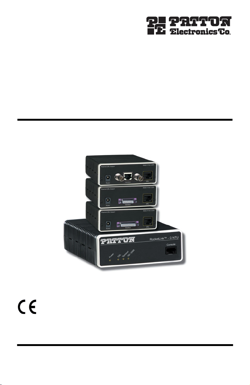
RocketLink-G™ Model 3088 Series
G.SHDSL NTU with Fixed
Serial Interfaces
Quick Start Guide
Important
intended nor approved for use in an industrial or residential environment.
Document Number: 03325U7-001 Rev. C
Part Number: 07M3088-QS
Revised: July 17, 2008
—This is a Class A device and is intended for use in a light industrial environment. It is not
Sales Office: +1 (301) 975-1000
Technical Support: +1 (301) 975-1007
E-mail: support@patton.com
WWW: www.patton.com
Page 2

• This device contains no user serviceable parts. The equipment
shall be returned to Patton Electronics for repairs, or repaired
by qualified service personnel.
WARNING
• AC Powered Units: The external power adaptor shall be a
listed Limited Power Source. Ensure that the power cable used
meets all applicable standards for the country in which it is to
be installed, and that it is connected to a wall outlet which has
earth ground. The mains outlet that is utilized to power the
device shall be within 10 feet (3 meters) of the device, shall
be easily accessible, and protected by a circuit breaker.
• DC Powered Units: The interconnecting cables shall be rated
for proper voltage, current, anticipated temperature, flammability, and mechanical serviceability.
• Hazardous network voltages are present in WAN ports,
regardless of whether power to the unit is ON or OFF. To avoid
electric shock, use caution when near WAN ports. When
detaching the cables, detach the end away from the device
first.
•
Do not work on the system or connect or disconnect cables during periods of lightning activity.
1.0 Select configuration method
Before powering up, you must select one of the following methods for configuring your RocketLink-G:
•
Plug ‘n’ Play
—The RocketLink-G comes factory-configured for Plug ’n’ Play configuration when connected
to a service-provider network.
•
DIP Switch
—For deploying the RocketLink-G in back-to-back applications. To use DIP-switch configuration
you must first set the DIP switches to a position other than all OFF or all ON before powering-up the RocketLink-G. To configure your NTU using the DIP switches, refer to the section entitled “Hardware (DIP-switch)
configuration” in the
•
Software Configuration
RocketLink-G Model 3088 Series Getting Started Guide.
—Allows you to modify configurable parameters by connecting a PC to the console port and issuing software commands. To use software configuration you must set all the DIP switches to
the ON position before powering-up the RocketLink-G. To configure your NTU via the console port, refer to
section “Software (CLI) configuration” in the
2
RocketLink-G Model 3088 Series Getting Started Guide.
Model 3088 Quick Start Guide
Page 3
2.0 Power up the NTU
Your G.SHDSL NTU comes with one of the following power supply options:
•
External AC adaptor with detachable power cord
External DC power supply with terminal block connector (model 48V-PSM3)
•
2.1 Models with external AC adaptor
1.
Connect female plug of the AC power cord to the AC adaptor provided.
2.
Connect the barrel-type connector of the AC adaptor to the
3.
Insert the male plug of the AC power cord into an AC power outlet (100–240 VAC).
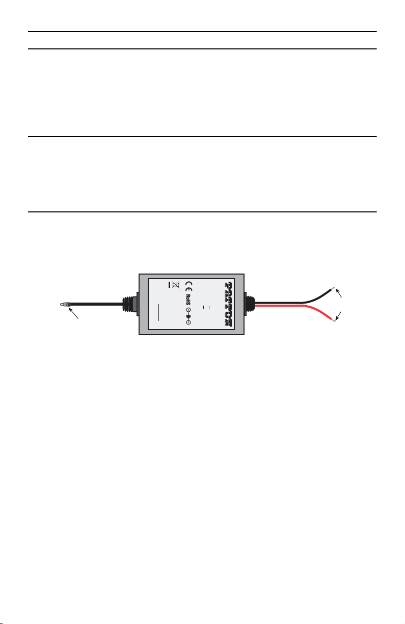
2.2 Models with external DC power supply
The 36-60 VDC DC to DC adapter is supplied with the DC version of the Model 3088. The black and red leads
plug into a DC source (nominal 48VDC) and the barrel power connector plugs into the barrel power supply jack
on the 3088. (See
figure 1
).
Power
connector on the RocketLink-G.
To Power
Supply Jack
Barrel power connector
S/N: G01234567890
MADE IN CHINA BY SUNNY
Figure 1.
SWITCHING POWER SUPPLY
MODEL : SYD1106-0505
INPUT : 36-60V 0.2A MAX
OUTPUT : +5V 1.0A
OUTPUT POWER : 5W MAX
DC Power Supply
-Vin
+Vin
To -48VDC
Source
Black lead (-V)
Red lead (+V)
Model 3088 Quick Start Guide
3
Page 4
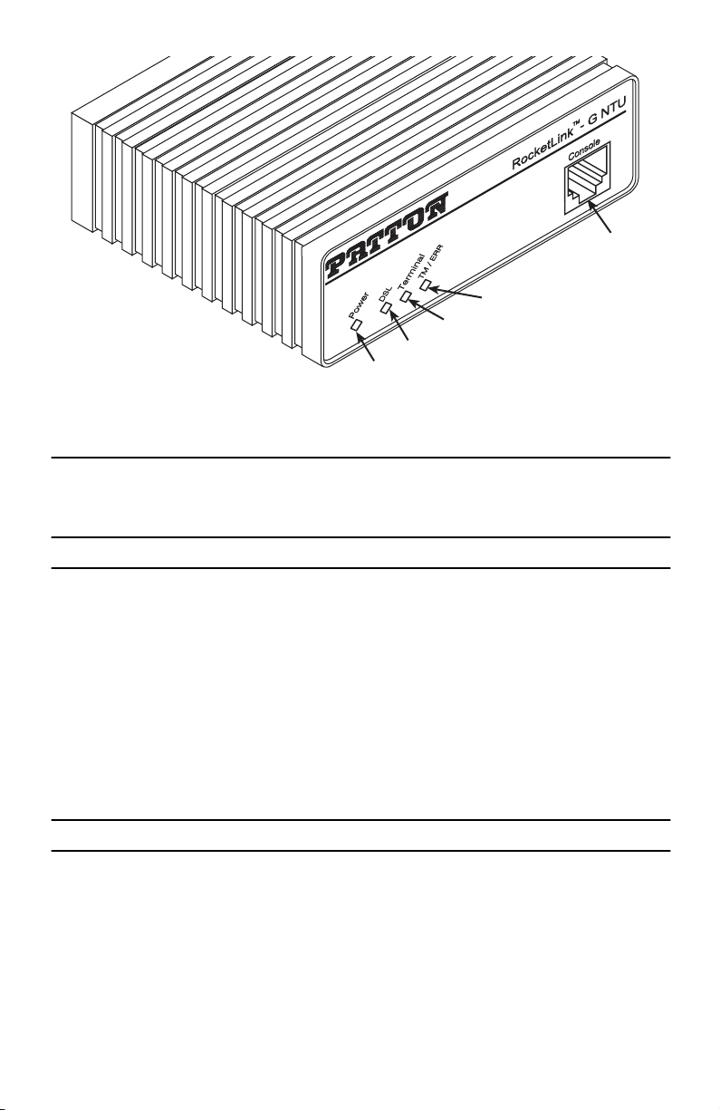
2.3 Power up indication
Figure 2.
Console
TM / ERR
Terminal
DSL
Power
Model 3088/CA front panel
Verify that the
Power
LED (see
figure 2
) illuminates and remains lit.
3.0 Connect the G.SHDSL port
1.
Obtain single-twisted-pair cable with an RJ-45 plug connector at each end.
2.
Plug one end of the cable into the RJ-45 socket (labelled
—
If you are connecting to a DSL service
DSL)
on the RocketLink-G NTU.
, plug the other end of the cable into the RJ-45 wall
socket that provides your G.SHDSL service.
—
If connecting to another RocketLink-G,
verify the other end of the cable is connected to the
DSL port on other RocketLink-G and the DSL port is correctly configured.
3.
When a DSL link is established, the front-panel
DSL
LED will turn on.
4.0 Connect the serial port
Your RocketLink-G comes with one of the following serial WAN ports for connection to an NTU:
•
V.35 (DB-25F)—Model 3088/CA
X.21 (DB-15)—Model 3088/D
•
•
T1/E1 (120-Ohm RJ-48C and dual 75-Ohm BNC connectors)—Model 3088/K
•
T1/E1 (RJ-48C)—Model 3088/T
4
Model 3088 Quick Start Guide
Page 5

Connect the serial cable to the RocketLink-G serial port as follows:
1.
Attach the male connector of the serial cable to the female serial connector on the RocketLink-G.
2.
Attach the other end of the cable to the serial connector on the local serial NTU.
Note
The V.35 interface is wired as a DCE. To connect the V.35 interface to third-party equipment wired as a
DCE, you must use a tail-circuit cable. You can purchase a tail-circuit cable from a datacom-supply vendor. A tail-circuit cable will cross-over the necessary V.35 signals so that the two DCE interfaces
can communicate.
Note
You can connect the V.35 interface to an M/34 connector using Patton’s Model 2-34F25M
interface adapter.
Note
The X.21 interface is wired as a DCE. If you need to change the orientation ti DTE, refer to section “
necting the Model 3088/D (X.21) Serial Interface”
The X.21 interface requires a cable with a male DB-15 connector.
Note
You can configure the T1/E1 interface to either recover the network clock from the T1/E1 line or supply
the network clock for the T1/E1 line.
in the
Model 3088 Series Getting Started Guide,
5.0 Additional information
Con-
For detailed information about installing, configuring, operating, and troubleshooting, refer to the
Series Getting Started Guide
on the enclosed Patton CD-ROM or at
www.patton.com/manuals
A.0 Compliance Information
A.1 Compliance
EMC:
•
FCC Part 15, Class A
EN55022, Class A
•
•
EN55024
•
GOST-R
Safety:
UL 60950-1/CSA C22.2 N0. 60950-1
•
•
IEC/EN60950-1
•
AS/NZS 60950-1
•
GOST-R
PSTN Regulatory:
•
FCC Part 68
CS03
•
Model 3088
.
Model 3088 Quick Start Guide
5
Page 6

•
TBR12 & 13 (K and T models)
AS/ACIF S016:2001 (K and T models)
•
•
AS/ACIF S043:2003
•
•
•
•
-1979, expires 21.04.2011(3088/T/EUI)
-1980, expires 21.04.2011(3088/K/EUI)
-1981, expires 21.04.2011(3088/D/EUI)
-1982, expires 21.04.2011(3088/CA/EUI)
A.2 FCC Part 68 (ACTA) Statement
This equipment complies with Part 68 of FCC rules and the requirements adopted by ACTA. On the bottom side of
this equipment is a label that contains—among other information—a product identifier in the format
AAAEQ##TXXXX
. If requested, this number must be provided to the telephone company.
US:
The method used to connect this equipment to the premises wiring and telephone network must comply with the
applicable FCC Part 68 rules and requirements adopted by the ACTA.
If this equipment causes harm to the telephone network, the telephone company will notify you in advance that
temporary discontinuance of service may be required. But if advance notice isn’t practical, the telephone company will notify the customer as soon as possible. Also, you will be advised of your right to file a complaint with
the FCC if you believe it is necessary.
The telephone company may make changes in its facilities, equipment, operations or procedures that could
affect the operation of the equipment. If this happens the telephone company will provide advance notice in
order for you to make necessary modifications to maintain uninterrupted service.
If trouble is experienced with this equipment, for repair or warranty information, please contact our company. If
the equipment is causing harm to the telephone network, the telephone company may request that you disconnect the equipment until the problem is resolved.
Connection to party line service is subject to state tariffs. Contact the state public utility commission, public service commission or corporation commission for information.
1.3 Radio and TV Interference (FCC Part 15)
This equipment generates and uses radio frequency energy, and if not installed and used properly—that is, in
strict accordance with the manufacturer's instructions—may cause interference to radio and television reception. This equipment has been tested and found to comply with the limits for a Class A computing device in accordance with the specifications in Subpart B of Part 15 of FCC rules, which are designed to provide reasonable
protection from such interference in a commercial installation. However, there is no guarantee that interference
will not occur in a particular installation. If the equipment causes interference to radio or television reception,
which can be determined by disconnecting the cables, try to correct the interference by one or more of the following measures: moving the computing equipment away from the receiver, re-orienting the receiving antenna,
and/or plugging the receiving equipment into a different AC outlet (such that the computing equipment and
receiver are on different branches).
6
Model 3088 Quick Start Guide
Page 7

1.4 Industry Canada Notice
This equipment meets the applicable Industry Canada Terminal Equipment Technical Specifications. This is confirmed by the registration number. The abbreviation, IC, before the registration number signifies that registration was performed based on a Declaration of Conformity indicating that Industry Canada technical specifications
were met. It does not imply that Industry Canada approved the equipment.
This Declaration of Conformity means that the equipment meets certain telecommunications network protective,
operational and safety requirements. The Department does not guarantee the equipment will operate to the
user's satisfaction. Before installing this equipment, users should ensure that it is permissible to be connected to
the facilities of the local telecommunications company. The equipment must also be installed using an acceptable
method of connection. In some cases, the company’s inside wiring associated with a single line individual service
may be extended by means of a certified connector assembly (telephone extension cord). The customer should
be aware that compliance with the above condition may not prevent degradation of service in some situations.
Repairs to some certified equipment should be made by an authorized maintenance facility designated by the
supplier. Any repairs or alterations made by the user to this equipment, or equipment malfunctions, may give
the telecommunications company cause to request the user to disconnect the equipment. Users should ensure for
their own protection that the ground connections of the power utility, telephone lines and internal metallic water
pipe system, are connected together. This protection may be particularly important in rural areas.
A.5 EC Declaration of Conformity
(See section
Product Description:
A.6 “EG-Konformitätserklärung”
RocketLink-G 3088 Series
for German version.)
This equipment conforms to the requirements of Council Directive 1999/5/EC on the approximation of the laws
of the member states relating to Radio and Telecommunication Terminal Equipment and the mutual recognition
of their conformity.
The safety advice in the documentation accompanying the products shall be obeyed.
The conformity to the above directive is indicated by the CE sign on the device.
The signed Declaration of Conformity can be downloaded from
www.patton.com/certifications/.
A.6 EG-Konformitätserklärung
(see section
Produktbezeichnung
A.5 “EC Declaration of Conformity”
: RocketLink-G 3088 Sendereihe
for English version)
Die bezeichneten Produkte stimmen in der von uns in Verkehr gebrachten Ausführung mit den Vorschriften folgender Richtlinie überein:
R&TTE 1999/5/EG
Richtlinie des europäischen Parlaments und des Rates zur Angleichung der Rechtsvorschriften der
Mitgliedstaaten über Funkanlagen und Telekommunikations-Endeinrichtungen und die gegenseitige
Anerkennung ihrer Konformität.
Model 3088 Quick Start Guide
7
Page 8

Die Sicherheitshinweise in der mitgelieferten Produktdokumentation sind zu beachten.
Die Konformität mit der oben erwähnten Richtlinie wird durch das CE-Zeichen auf dem
Gerät bestätigt.
Die unterzeichnete Konformitätserklärung kann heruntergeladen werden von:
certifications/.
A.7 Authorized European Representative
D R M Green
European Compliance Services Limited.
Oakdene House, Oak Road
Watchfield,
Swindon, Wilts SN6 8TD, UK
www.patton.com/
8
Model 3088 Quick Start Guide
Page 9

Copyright statement
Copyright © 2007, Patton Electronics Company. All rights reserved.
The information in this document is subject to change without notice. Patton Electronics assumes no
liability for errors that may appear in this document.
Trademarks statement
The term
RocketLink-G
is a trademark of Patton Electronics Company. All other trademarks presented in this docu-
ment are the property of their respective owners.
Patton support headquarters in the USA
Online support: Available at
•
E-mail support: E-mail sent to
•
Telephone support: Standard telephone support is available five days a week—from
•
5:00 pm EST (1300
Support via VoIP: Contact Patton free of charge by using a VoIP ISP phone to call
•
Fax:
+1 (253) 663-5693
•
www.patton.com
support@patton.com
to
2200 UTC/GMT
will be answered within 1 business day
)—by calling
+1 (301) 975-1007
8:00 am
to
sip:support@patton.com
Alternate Patton support for Europe, Middle East, and Africa (EMEA)
•
Telephone support: Standard telephone support is available five days a week—from
5:00 pm CET (0900
•
Fax:
+41 (0)31 985 25 26
to
1800 UTC/GMT
)—by calling
+41 (0)31 985 25 55
8:00 am
to
Note For additional service and support information, refer to the “Contacting Patton for assistance” chapter
of the RocketLink-G 3088 Getting Started Guide located on the CD-ROM that came with your RocketLink-G
Router or available online at www.patton.com.
Warranty, Trademark, & Compliance Information
For warranty, trademark and compliance information, refer to the RocketLink-G 3088 Getting Started Guide located
on the CD-ROM that came with your NTU or available online at www.patton.com.
In accordance with the requirements of council directive 2002/96/EC on Waste of
Electrical and Electronic Equipment (WEEE), ensure that at end-of-life you separate
this product from other waste and scrap and deliver to the WEEE collection system in
your country for recycling.
Model 3088 Quick Start Guide
9
Page 10

NOTES
____________________________________________________________________
____________________________________________________________________
____________________________________________________________________
____________________________________________________________________
____________________________________________________________________
____________________________________________________________________
____________________________________________________________________
____________________________________________________________________
____________________________________________________________________
____________________________________________________________________
____________________________________________________________________
____________________________________________________________________
____________________________________________________________________
____________________________________________________________________
____________________________________________________________________
____________________________________________________________________
10 Model 3088 Quick Start Guide
Page 11

NOTES
____________________________________________________________________
____________________________________________________________________
____________________________________________________________________
____________________________________________________________________
____________________________________________________________________
____________________________________________________________________
____________________________________________________________________
____________________________________________________________________
____________________________________________________________________
____________________________________________________________________
____________________________________________________________________
____________________________________________________________________
____________________________________________________________________
____________________________________________________________________
____________________________________________________________________
____________________________________________________________________
Model 3088 Quick Start Guide 11
Page 12

NOTES
____________________________________________________________________
____________________________________________________________________
____________________________________________________________________
____________________________________________________________________
____________________________________________________________________
____________________________________________________________________
____________________________________________________________________
____________________________________________________________________
____________________________________________________________________
____________________________________________________________________
____________________________________________________________________
____________________________________________________________________
____________________________________________________________________
____________________________________________________________________
____________________________________________________________________
____________________________________________________________________
12 Model 3088 Quick Start Guide
 Loading...