

Patton electronic 3087 User Manual
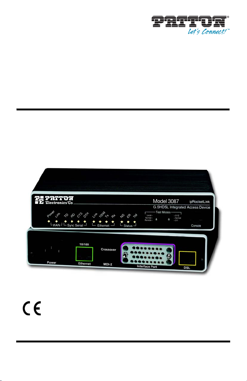
ipRocketLink™ Model 3087
Serial G.SHDSL Bridge/Router
Quick Start Guide
Important
intended nor approved for use in an industrial or residential environment.
Part Number: 07M3087-QS, Rev. C
Revised: February 15, 2012
—This is a Class A device and is intended for use in a light industrial environment. It is not
Sales Office: +1 (301) 975-1000
Technical Support: +1 (301) 975-1007
E-mail: support@patton.com
WWW: www.patton.com
• This device contains no user serviceable parts. The equipment shall be
returned to Patton Electronics for repairs, or repaired by qualified
service personnel.
WARNING
• Mains Voltage: Do not open the case the when the power cord is
attached. Line voltages are present within the power supply when
the power cords are connected. The mains outlet that is utilized to
power the devise shall be within 10 feet (3 meters) of the device,
shall be easily accessible, and protected by a circuit breaker.
• For AC powered units, ensure that the power cable used meets all
applicable standards for the country in which it is to be installed, and
that it is connected to a wall outlet which has earth ground.
• For units with an external power adapter, the adapter shall be a
listed Limited Power Source.
• Hazardous network voltages are present in WAN ports regardless of
whether power to the unit is ON or OFF. To avoid electric shock, use
caution when near WAN ports. When detaching the cables, detach the
end away from the device first.
• Do not work on the system or connect or disconnect cables during
periods of lightning activity.
1.0 Power up the Bridge/Router
The interconnecting cables shall be acceptable for external use and shall be rated for
the proper application with respect to voltage, current, anticipated temperature, flammability, and mechanical serviceability.
CAUTION
Your ipRocketLink comes with one of the following power supply options:
•
Internal AC powqer supply with detachable power cord
•
External AC adapter with detachable power cord
1.1 Models with internal AC power supply
1. Insert the female end of the AC power cord into the internal power supply connector.
2. Connect the male end of the power cord into an AC power outlet (100–240 VAC).
1.2 Models with external AC adaptor
1. Connect female plug of the AC power cord to the AC adaptor provided.
2. Connect the barrel-type connector of the AC adaptor to the barrel-type power jack on the ipRocketLink.
2 Model 3087 Quick Start Guide
3. Insert the male plug of the AC power cord into an AC power outlet (100–240 VAC)
.
1.3 Power-up indication
The Power LED blinks as the ipRocketLink is powering up. When the Power LED stops blinking and remains lit,
the ipRocketLink is ready for you to configure.
2.0 Configure the IP address
The ipRocketLink is shipped with a factory-configured IP address assigned to the Ethernet LAN port (green outline). The address is 192.168.200.10/24. In most cases, you must change the address to be on the same subnet
as your PC, as described in the procedures below. If you are not sure which IP address to use for your installation, contact your network administrator.
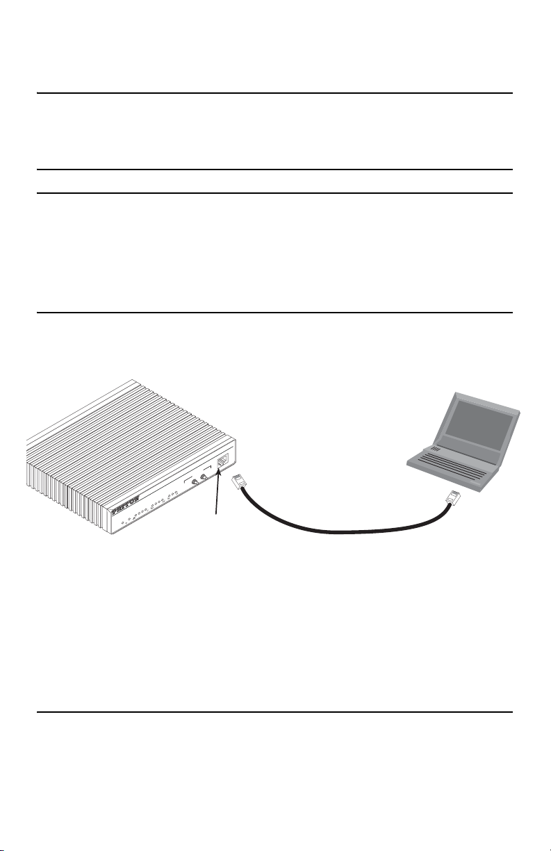
2.1 Connect a PC and log in
1. Using the included combination RS232/Ethernet cable and DB9-RJ45 adapter, connect a PC’s serial port
to the ipRocketLink’s Console port (see figure 1).
PC with
terminal emulator
ipRocketLink
Model 3086
Console
G.SHDSL Integrated Access Device
- 511E
- Normal
Test Modes
- 511
Local Normal Remote -
TM
ER
NS
Rx
Status
Tx
100M
Link
DTR
Ethernet
CTS
RD
TD
Link
Sync Serial
Power
WAN
Connect to Console port
Serial port
Figure 1. Connecting ipRocketLink to the PC’s serial port
2. Start a HyperTerminal session on the PC using the settings:
9600 bps, 8 data bits, 1 stop bit, no parity, no flow control
3. Log in to the ipRocketLink using the factory-default login and password:
Login: superuser
Password: superuser
Login successful
2.2 Modify the IP address
1. Display current IP interface settings for the ipRocketLink Ethernet LAN port.
fi
ip list interfaces <enter>
Model 3087 Quick Start Guide 3
IP Interfaces:
ID | Name | IP Address | DHCP | Transport
---|------|----------------|----------|------------- 1 | ip1 | 192.168.200.10 | disabled | <bridge>
----------------------------------------------
------
2. Modify the IP address for the LAN port according to your network requirements.
fi
ip set interface ip1 ipaddress 10.10.10.5 255.255.255.0
Note The above IP address (
10.10.10.5/24)
is only an example. You must choose an IP address on the same
subnet as your PC.
3. Verify the new address is correct and save it in system boot memory.
fi
ip list interfaces <enter>
fi
system config save <enter>
fi
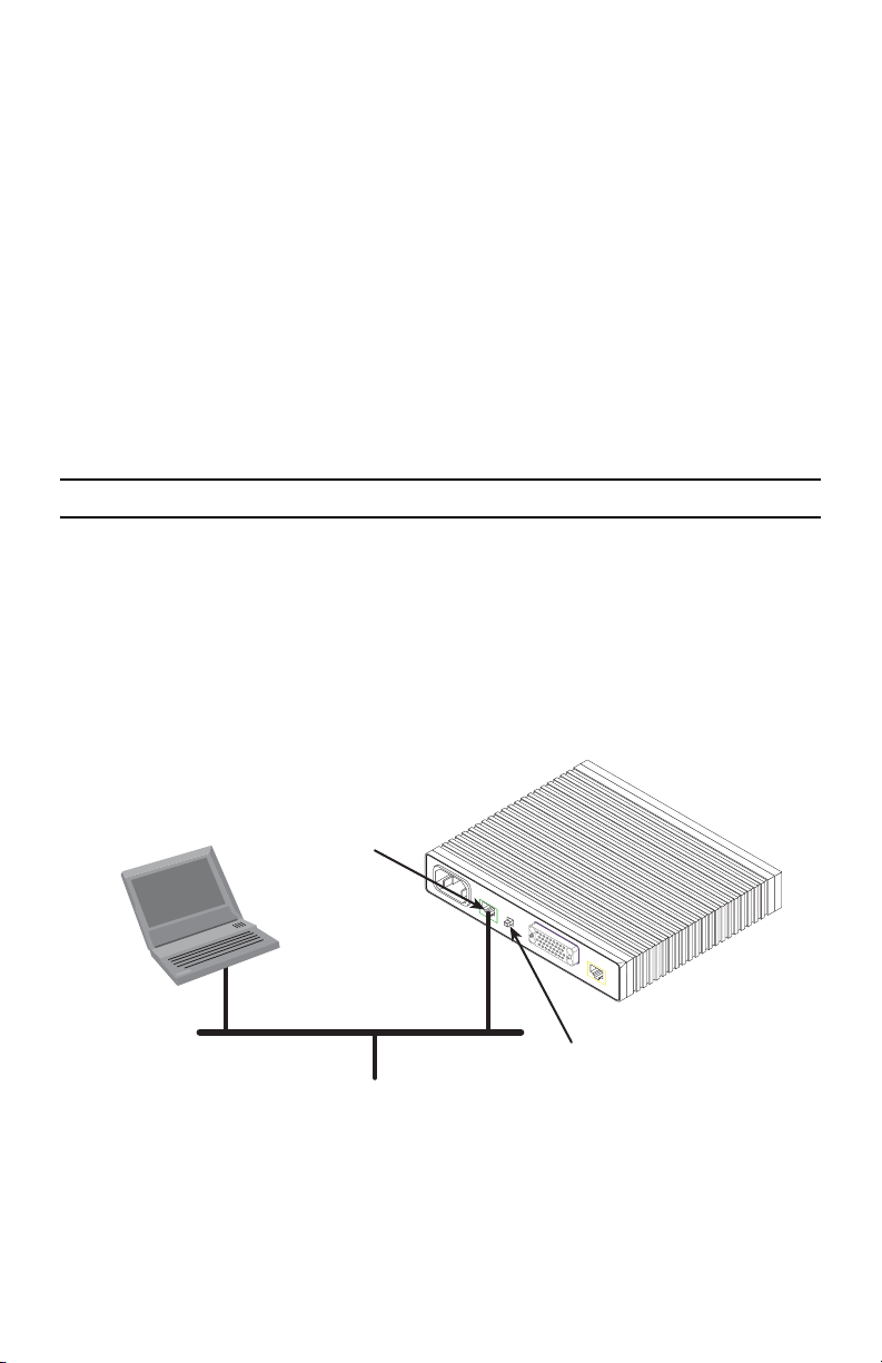
3.0 Connect to the local IP network
Now you can connect the ipRocketLink to your local IP network and complete the remaining configuration from
your PC using a standard web browser.
Connect the ipRocketLink’s Ethernet port (green) to the same Ethernet segment as your PC (see figure 2). The
front-panel Ethernet Link LED should turn on. If it does not, press the rear-panel MDI-X switch so that the Ethernet
Link LED illuminates.
You can check the connection with the ping command. For example shown in figure 2, you would ping
10.10.10.5 from a PC on the IP network.
Connect to Ethernet port
Power
10/100
Crossover
Ethernet
PC
Ethernet port
MDI-X
Interface Port
DSL
MDI-X switch
Figure 2. Connecting the ipRocketLink to the local IP network
4 Model 3087 Quick Start Guide
 Loading...