

Page 1
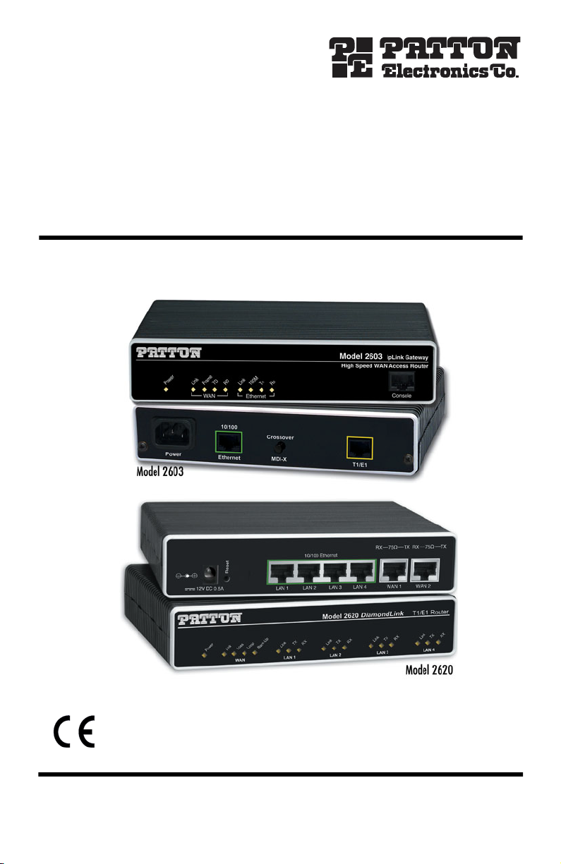
IPLink™ Model 2603 & 2620
WAN Access Router
Quick Start Guide
Important
intended nor approved for use in an industrial or residential environment.
Document Number: 03323U7-001 Rev. E
Part Number: 07M2620-QS
Revised: October 17, 2008
—This is a Class A device and is intended for use in a light industrial environment. It is not
Sales Office: +1 (301) 975-1000
Technical Support: +1 (301) 975-1007
E-mail: support@patton.com
WWW: www.patton.com
Page 2

WARNING
• This device contains no user serviceable parts. The equipment shall be
returned to Patton Electronics for repairs, or repaired by qualified
service personnel.
• Mains Voltage: Do not open the case the when the power cord is
attached. Line voltages are present within the power supply when
the power cords are connected. The mains outlet that is utilized to
power the devise shall be within 10 feet (3 meters) of the device,
shall be easily accessible, and protected by a circuit breaker.
• For AC powered units, ensure that the power cable used meets all
applicable standards for the country in which it is to be installed, and
that it is connected to a wall outlet which has earth ground.
• For units with an external power adapter, the adapter shall be a
listed Limited Power Source.
• Hazardous network voltages are present in WAN ports regardless of
whether power to the unit is ON or OFF. To avoid electric shock, use
caution when near WAN ports. When detaching the cables, detach the
end away from the device first.
• Do not work on the system or connect or disconnect cables during
periods of lightning activity.
1.0 Power up the router
The interconnecting cables shall be acceptable for external use and shall be rated for
the proper application with respect to voltage, current, anticipated temperature, flammability, and mechanical serviceability.
CAUTION
Your router comes with one of the following power supply options:
•
External AC adaptor with included power cord
Use only a 12V certified
Limited Power Source
CAUTION
Internal AC power supply
•
Internal DC power supply—no power accessories are included
•
1.1 Models with external AC adaptor
1.
Connect female plug of the AC power cord to the AC adaptor provided.
2
external power adaptor marked
IPLink 2603 & 2620 Quick Start Guide
LPS.
Page 3
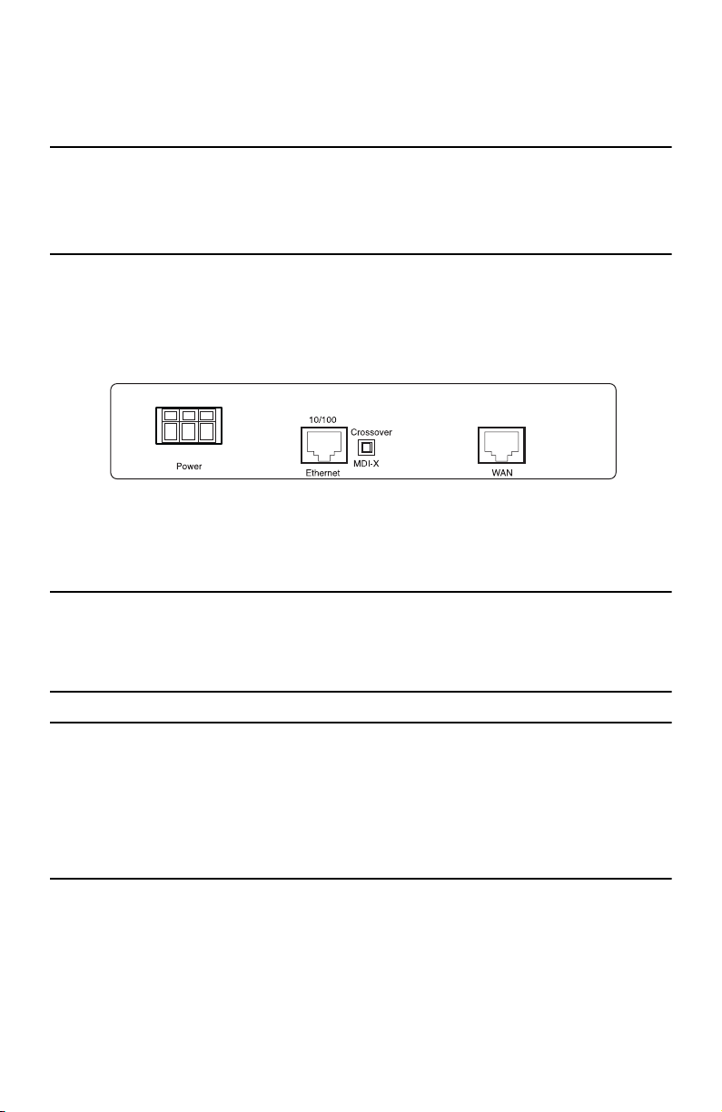
2.
Connect the barrel-type connector of the AC adaptor to the barrel-type
3.
Insert the male plug of the AC power cord into an AC power outlet (100–240 VAC).
Power
jack on the IPLink router.
1.2 Models with internal AC power supply
1.
Insert the female end of the AC power cord into the internal power supply connector.
2.
Connect the male end of the power cord into an AC power outlet (100–240 VAC).
1.3 Models with internal DC power supply
1.
Strip insulation 1/4-inch from the electrical wires that will connect the DC power source to the IPLink.
2.
Connect the positive (+) terminal from the power source to the positive (+) terminal on the IPLink.
3.
Connect the ground terminal from the power source to the ground terminal (E) on the IPLink.
4.
Connect the negative (-) terminal from the power source with to the negative (-) terminal on the IPLink.
+E-
Note
“+”, “E”, and “-” may be unlabeled.
Figure 1.
Connecting the DC power supply
1.4 Power-up indication
The
Power
LED blinks as the IPLink is powering up. When the
Power
LED stops blinking and remains lit, the
IPLink is ready for you to configure.
2.0 Configure the IP address
The IPLink is shipped with a factory-configured IP address assigned to the
address is
192.168.200.10/24
. In most cases, you must change the address to be on the same subnet as your
PC, as described in the procedures below. If you are not sure which IP address to use for your installation, contact
your network administrator.
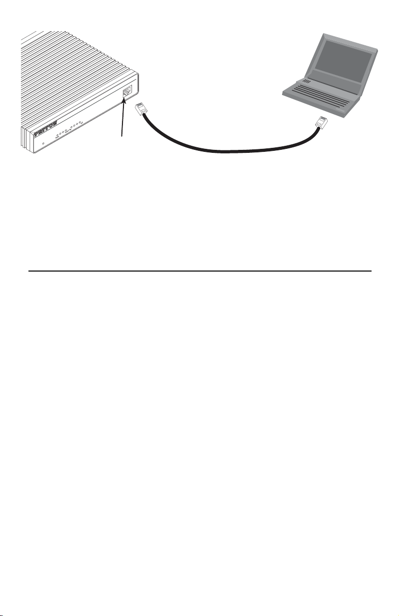
2.1 Connecting a PC and logging in
1.
Using the included combination RS232/Ethernet cable and DB9-RJ45 adapter, connect a PC’s serial port
to the IPLink’s
Console
port (see
figure 2
).
Ethernet
LAN port (green outline). The
IPLink 2603 & 2620 Quick Start Guide
3
Page 4
Link
Frame
TD
RD
Link
100M
Tx
Rx
WAN Ethernet
Power
Console
ipLink Gateway
High Speed WAN Access Router
Model 2603
Connect to Console port
PC with
terminal emulator
Serial port
Figure 2.
2.
Start a HyperTerminal session on the PC using the settings:
Connecting IPLink to the PC’s serial port
9600 bps, 8 data bits, 1 stop bit, no parity, no flow control
3.
Log in to the IPLink using the factory-default login and password:
Login:
superuser
Password: superuser
Login successful
2.2 Modifying the IP address
1.
Display current IP interface settings for the IPLink
→→
ip list interfaces <enter>
→→
Ethernet
LAN port.
IP Interfaces:
ID | Name | IP Address | DHCP | Transport
---|------|----------------|----------|------------- 1 | ip1 | 192.168.200.10 | disabled | <eth1>
----------------------------------------------
2.
Modify the IP address for the LAN port according to your network requirements.
→→
ip set interface ip1 ipaddress 10.10.10.5 255.255.255.0
→→
Note
The above IP address (
subnet as your PC
3.
Verify the new address is correct and save it in system boot memory.
→→
ip list interfaces <enter>
→→
→→
system config save <enter>
→→
→→
→→
10.10.10.5/24)
.
is only an example. You must choose an IP address on the same
------
Now you can connect the IPLink to your local IP network and complete the remaining configuration from your
PC using a standard web browser.
4
IPLink 2603 & 2620 Quick Start Guide
Page 5

3.0 Connect to the local IP network
Connect the IPLink’s (green)
Note
The Model 2620 does not have an MDI-X switch, so you must use a cable wired straight-through to con-
Ethernet
port to the same Ethernet segment as your PC (see
figure 3
).
nect the Model 2620’s Ethernet port to the IP network.
If you have a Model 2603, press the MDI-X switch until the
PC
Ethernet port
Ethernet Link
Connect to
Ethernet port
LED turns on.
10/100
Power
Crossover
Ethernet
MDI-X
RX
TX
WAN
MDI-X switch
Figure 3.
You can check the network connection with the ping command. For example, you would ping
Connecting the IPLink to the local IP network (Model 2603/K shown)
10.10.10.5
from
your PC.
4.0 Log onto the web management interface
You will now access the web management Graphical User Interface (GUI) to configure the IPLink using a standard web browser (such as Internet Explorer or Netscape browser).
1.
At your PC, open a web browser and enter the IP address you assigned to the IPLink’s Ethernet LAN port
in step 2 of section
2.
Log in to the web management home page using the username
2.2 “Modifying the IP address”
on page 4.
superuser
and the password
superuser
.
IPLink 2603 & 2620 Quick Start Guide
5
Page 6

Figure 4.
3.
Now you can use the IPLink’s web management pages to complete your configuration (see section
“Complete the installation”
IPLink web management home page
6.0
on page 7).
5.0 Connect the WAN port
The IPLink 2603/T, 2603/K, and 2620 come with a T1/E1 WAN interface (presented on an RJ-48C connector
with selectable line impedances of 100-ohms for T1 and 120-ohms for E1 lines). The Model 2603 has one RJ48C connector and the 2620 has two. The Model 2603/K and 2620/KK also come with dual BNC connectors for
alternate connection to unbalanced 75-ohm E1 lines.
To connect the WAN port on a Model 2620 or Model 2603/T, or if you plan to use the RJ-48C port on a 2603/K,
refer to section “Connecting to the RJ-48C WAN port”. Otherwise, refer to section “Connecting to the unbalanced
75-ohm TX and RX WAN ports (Model 2603/K and 2620/KK only)” to install cables onto the BNC connectors on
the 2603/K and 2620/KK models.
Connecting to the RJ-48C WAN port
1.
Obtain a twisted-pair cable with an RJ-48C plug connector at each end.
2.
Plug one end of the cable into the RJ-48C socket (labeled
3.
Plug the other end of the cable into the T1/E1 device.
4.
Repeat steps 1 through 3 to install the remaining WAN cables on a Model 2620
Connecting to the unbalanced 75-ohm TX and RX WAN ports (Model 2603/K
and 2620/KK only)
1.
Obtain a coaxial cable with a BNC connector at each end.
2.
Plug one end of the cable into the transmit socket (labeled TX)
of the cable into the receive port of the E1 device.
WAN) on the IPLink Router.
on the IPLink Router. Plug the other end
6
IPLink 2603 & 2620 Quick Start Guide
Page 7

3.
Plug one end of the cable into the receive socket (labeled RX)
on the IPLink Router. Plug the other end of
the cable into the transmit port of the E1 device.
6.0 Complete the installation
To finish configuring your IPLink, and for detailed information about installing, configuring, operating, and troubleshooting, refer to the
cation notes, available on the enclosed Patton CD-ROM or at
Models 2603, 2621, and 2635 IPLink Series High Speed Routers User Guide and appli-
www.patton.com.
A.0 Customer and Technical Support
Toll-Free VoIP support: call
Online support: www
E-mail support:
support@patton.com
sip:support@patton.com
.patton.com
—answered within 1 business day
with a VoIP SIP phone
Telephone support:
•
Standard: +1 (301) 975-1007 (USA), Monday–Friday: 8:00 am to 5:00 pm EST (1300 to
2200 UTC/GMT)
•
Alternate: +41 (0)31 985 25 55 (Switzerland), Monday–Friday: 8:00 am to 5:00 pm CET (0900 to 1800
UTC/GMT)
Fax:
+1 (253) 663-5693
(USA)
or +41 (0)31 985 25 26 (
Switzerland)
B.0 Compliance Information
B.1 Compliance
EMC:
FCC Part 15, Class A
•
EN55022, Class A
•
EN55024
•
Safety:
UL60950-1/CSA C22.2 No. 60950-1
•
IEC/EN 60950-1
•
AS/NZS 60950-1
•
PSTN Regulatory:
These devices are not intended for connection to the PSTN.
•
IPLink 2603 & 2620 Quick Start Guide
7
Page 8

B.2 Radio and TV Interference (FCC Part 15)
This equipment generates and uses radio frequency energy, and if not installed and used properly—that is, in
strict accordance with the manufacturer's instructions—may cause interference to radio and television reception. This equipment has been tested and found to comply with the limits for a Class A computing device in accordance with the specifications in Subpart B of Part 15 of FCC rules, which are designed to provide reasonable
protection from such interference in a commercial installation. However, there is no guarantee that interference
will not occur in a particular installation. If the equipment causes interference to radio or television reception,
which can be determined by disconnecting the cables, try to correct the interference by one or more of the following measures: moving the computing equipment away from the receiver, re-orienting the receiving antenna,
and/or plugging the receiving equipment into a different AC outlet (such that the computing equipment and
receiver are on different branches).
B.3 CE Declaration of Conformity
Product Description: IPLink 2603, 2620
We certify that the apparatus described above conforms to the requirements of Council Directive 2004/108/EC
on the approximation of the laws of the member states relating to electromagnetic compatibility; and Council
Directive 2006/95/EC on the approximation of the laws of the member states relating to electrical equipment
designed for use within certain voltage limits.
The safety advice in the documentation accompanying this product shall be obeyed. The conformity to the above
directive is indicated by the CE sign on the device.
The safety advises in the documentation accompanying the products shall be obeyed. The
conformity to the above directive is indicated by the CE sign on the device.
The signed Declaration of Conformity can be downloaded from www.patton.com/certifications/.
B.4 Authorized European Representative
D R M Green
European Compliance Services Limited.
Avalon House, Marcham Road
Abingdon,
Oxon OX14 1UD, UK
8
IPLink 2603 & 2620 Quick Start Guide
Page 9

Copyright statement
Copyright © 2008, Patton Electronics Company. All rights reserved.
The information in this document is subject to change without notice. Patton Electronics assumes no
liability for errors that may appear in this document.
Trademarks statement
The term IPLink is a trademark of Patton Electronics Company. All other trademarks presented in this document
are the property of their respective owners.
Warranty, Trademark, & Compliance Information
For warranty, trademark and compliance information, refer to the Models 2603, 2621, and 2635 IPLink Series
High Speed Routers User Guide located on the CD-ROM that came with your router or available online
at www.patton.com.
In accordance with the requirements of council directive 2002/96/EC on Waste of
Electrical and Electronic Equipment (WEEE), ensure that at end-of-life you separate
this product from other waste and scrap and deliver to the WEEE collection system in
your country for recycling.
IPLink 2603 & 2620 Quick Start Guide 9
Page 10

NOTES
____________________________________________________________________
____________________________________________________________________
____________________________________________________________________
____________________________________________________________________
____________________________________________________________________
____________________________________________________________________
____________________________________________________________________
____________________________________________________________________
____________________________________________________________________
____________________________________________________________________
____________________________________________________________________
____________________________________________________________________
____________________________________________________________________
____________________________________________________________________
____________________________________________________________________
____________________________________________________________________
10 IPLink 2603 & 2620 Quick Start Guide
Page 11

NOTES
____________________________________________________________________
____________________________________________________________________
____________________________________________________________________
____________________________________________________________________
____________________________________________________________________
____________________________________________________________________
____________________________________________________________________
____________________________________________________________________
____________________________________________________________________
____________________________________________________________________
____________________________________________________________________
____________________________________________________________________
____________________________________________________________________
____________________________________________________________________
____________________________________________________________________
____________________________________________________________________
IPLink 2603 & 2620 Quick Start Guide 11
Page 12

NOTES
____________________________________________________________________
____________________________________________________________________
____________________________________________________________________
____________________________________________________________________
____________________________________________________________________
____________________________________________________________________
____________________________________________________________________
____________________________________________________________________
____________________________________________________________________
____________________________________________________________________
____________________________________________________________________
____________________________________________________________________
____________________________________________________________________
____________________________________________________________________
____________________________________________________________________
____________________________________________________________________
12 IPLink 2603 & 2620 Quick Start Guide
 Loading...