

Page 1
Visuality™ Model T7714
Mobile Video System
Quick Start Guide
The compliance information in this document is incomplete and subject to change.
IMPORTANT
Part Number: 07MT7714-QS, Rev. B
Revised: March 1, 2012
Sales Office: +1 (301) 975-1000
Technical Support: +1 (301) 975-1007
E-mail: support@patton.com
WWW: www.patton.com
Page 2

WARNING
• The T7714 contains no user serviceable parts. The equipment
shall be returned to Patton Electronics for repairs, or repaired
by qualified service personnel.
• Mains Voltage: Line voltages are present when the power cord
is connected. The mains outlet shall be within 10 feet (3
meters) of the device, shall be easily accessible, and protected
by a circuit breaker.
• For AC powered units, ensure that the power cable used meets
all applicable standards for the country in which it is to be
installed, and that it is connected to a wall outlet which has
earth ground.
• For units with an external power adapter, the adapter shall be
a listed Limited Power Source.
• Hazardous network voltages are present in WAN ports,
regardless of whether power to the unit is ON or OFF. To
avoid electric shock, use caution when near WAN ports. When
detaching the cables, detach the end away from the device
first.
•
Do not work on the system or connect or disconnect cables dur-
ing periods of lightning activity.
1.0 Connect the ports
Note Figure 1 on page 3 shows the ports and connector types on the Model T7714.
1. Connect the Ethernet port (optional)– Use a straight-through or cross-over Ethernet cable to connect one of the
Ethernet (RJ-45) ports to the local LAN.
Note A T7714 unit typically operates in a vehicle where Ethernet cables are not required. You may want to
connect an Ethernet port to configure the T7714 or offload files.
2. Connect the Console port–Use a serial cable to connect the Console port (DB-9 connector) on the front panel of
the T7714 to an open serial port on a PC.
3. Connect cameras and audio–For each camera, connect the wire for power into the left slot on the terminal
block connector for the corresponding camera. Connect the wire for ground on the right slot on the terminal block
connector for each correesponding camera.
Use a 75-ohm BNC cable to connect the video and audio ports. Plug the male end of the BNC cable into the
T7714 VIDEO IN or AUDIO IN female connector. Plug the other end of the BNC cable into the corresponding port
on the camera.
4. Connect the GPS and cellular antennas–Use a SMA cable to connect the GPS and cellular (female SMA con-
nectors) antenna ports.
2 Visuality™ Model T7714 Quick Start Guide
Page 3
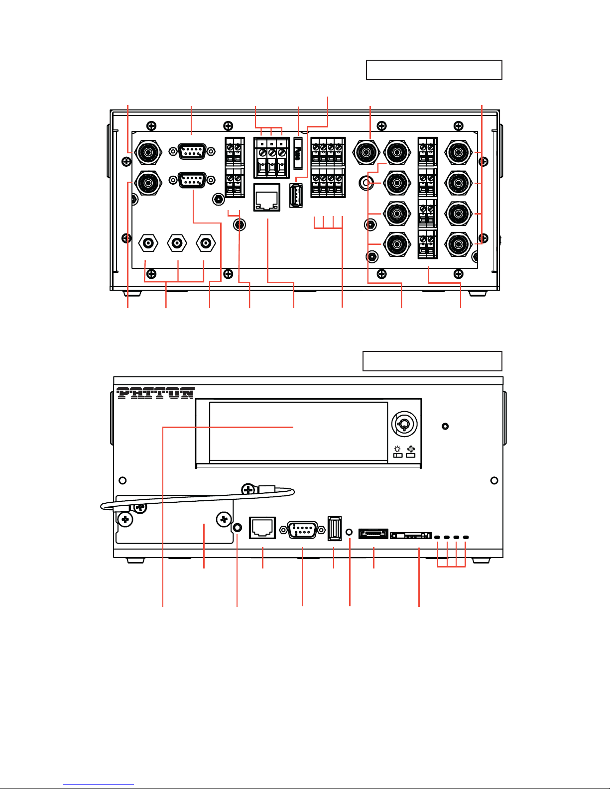
T7714 Rear Panel
Video to Display
(BNC)
VIDEO OUT
AUDIO OUT
GPS ANT 1 ANT 2
Audio
GPS & Cellular
to Display
(BNC)
Pan/Tilt/Zoom
Control (DB-9)
Antennas
(SMA)
PTZ
OBD II
On-Board
Diagnostics
(DB-9)
Main Power
(Terminal Block)
ACC GND +12V
AUX PWR
AUX GND
ETHERNET
Auxiliary
Power Output
(Terminal Block)
Fuse
(10A)
Fuse
USB
Gigabit
Ethernet
(RJ-45)
USB 2.0
INPUT PWR
INPUT GND
1 2 3 4
Microphone
Auxiliary
Inputs 1-4
(Terminal Block)
(BNC)
MIC
AUDIO IN
1
2
3
4
+12V GND
CAM PWR
Audio for
Cameras 1-4
(BNC)
(Terminal Block)
(BNC)
VIDEO IN
1
2
3
4
Power for
Cameras 1-4
T7714 Front Panel
Cameras 1-4
Modem
Removeable
Hard Drive
Cellular Modem
(Card Slot)
Headphone
Headphone Ethernet Console
Gigabit
USB
USB 2.0
Reset
Ethernet
(RJ-45)
Jack
Console Port
(DB-9)
Factory Reset
Button
Figure 1. Model T7714 Connectors
eSATA SIM Card
Interface Port for
External Hard Drive
(Serial ATA)
Reserved Slot
for SIM Card
T7714
HD Shutoff
Power
COM
Video
LEDs
Network
Visuality™ Model T7714 Quick Start Guide 3
Page 4

2.0 Connect the cellular modem
The T7714 provides a slot for a cellular modem card. To install a cellular modem in the T7714:
Network
Video
COM
Power
ard
C
IM
S
odem
M
phone
ead
H
Ethernet Con
sole
Cellular Modem
Card
Figure 2. Installing the cellular modem card on the T7714
1. Use a screwdriver to remove the Modem cover on the front of the T7714 unit.
2. Plug the cellular modem card into the antenna cable inside of the unit.
3. Slide the modem card into the tray inside the T7714 until the card clicks into place.
4. Use a screwdriver to reattach the Modem cover to the front of the T7714 unit.
ATA
eS
eset
R
B
S
U
To remove the cellular modem card, use a screwdriver to remove the Modem cover on the front of the T7714
unit. Gently press on the modem card. The card will eject from the card slot.
3.0 Connect power
Fuse
USB
Auxiliary
Inputs 1-4
(Terminal Block)
INPUT PWR
INPUT GND
1 2 3 4
AUDIO IN
MIC
VIDEO IN
1
1
2
2
3
3
VIDEO OUT
AUDIO OUT OBD II
Auxiliary
Power Output
(Terminal Block)
PTZ
AUX PWR
AUX GND
Main Power
(Terminal Block)
ACC GND +12V
ETHERNET
Figure 3. T7714 power connectors
To connect the main power:
1. Connect the wires for the power connector into the terminal block labeled ACC GND +12V.
2. Connect the wire for the vehicle accessory port into the ACC block.
3. Connect the wires for the vehicle battery into the GND and +12V blocks.
4. The unit will turn on when you connect the ACC wire to the vehicle accessory line. You may verify that the
Power LED on the front panel of the T7714 is lit.
4 Visuality™ Model T7714 Quick Start Guide
Page 5

4.0 Dock the unit (optional)
Some models of the T7714 are made to fit into a dock in a vehicle designed especially for Visuality models. The
dock allows you to easily swap remote T7714 units in and out of vehicles. Components for dockable T7714 units
are the same as standalone units.
To install a dockable T7714 unit into a dock in a vehicle, line up the T7714 unit with the metal guides on the
dock. Push the T7714 unit straight back to connect it with the dock. The DB-15 connector installs the GPS and cellular antennas. The DB-78 connector installs the power, video, audio, and other components.
DB-15 connector
for antennas
D-78 connector
for components
T7714 dock
guides
Figure 4. T7714 dock
5.0 Log into the unit
You can configure the Model T7714 using the Ethernet port and the Web Management Interface (WMI), or by
using the Console port and the Command Line Interface (CLI).
To configure the T7714 using the WMI, make sure that an Ethernet port is connected to the local LAN. Type the IP
address of the unit into a web browser and log in.
To configure the T7714 using the CLI, connect a PC to the unit’s console port. Open a terminal program on the PC
and create a connection with the default settings: 19200 baud rate, 8 data bits, no parity, and 1 stop bit.
Note For information on configuring the unit, refer to the Visuality™ Model T7714 User Manual and the Trin-
ityAE Adiminstrator’s Reference Guide, available online at www.patton.com/manuals/T7714.pdf and
www.patton.com/manuals/Trinity-arg.pdf.
Visuality™ Model T7714 Quick Start Guide 5
Page 6

6.0 Additional information
For detailed information about installing, configuring, operating, and troubleshooting your Model T7714, refer
to the following documents, available online at www.patton.com/manuals:
•
Visuality™ Model T7714 User Manual : www.patton.com/manuals/T7714.pdf
•
Visuality™ MVAS Deployment Guide: www.patton.com/manuals/Visuality.pdf
•
TrinityAE Administrator’s Reference Guide: www.patton.com/manuals/Trinity-arg.pdf
•
TrinityAE Feature Appendix: Media: www.patton.com/manuals/Trinity-Media-apd.pdf
6 Visuality™ Model T7714 Quick Start Guide
Page 7

Copyright statement
Copyright © 2012, Patton Electronics Company. All rights reserved.
The information in this document is subject to change without notice. Patton Electronics assumes no
liability for errors that may appear in this document.
Trademarks statement
The term Visuality is a trademark of Patton Electronics Company. All other trademarks presented in this document
are the property of their respective owners.
Patton support headquarters in the USA
•
Online support: Available at www.patton.com
•
E-mail support: E-mail sent to support@patton.com will be answered within 1 business day
•
Telephone support: Standard telephone support is available five days a week—from 8:00 am to
5:00 pm EST (1300 to 2200 UTC/GMT)—by calling +1 (301) 975-1007
•
Support via VoIP: Contact Patton free of charge by using a VoIP ISP phone to call sip:support@patton.com
•
Fax: +1 (253) 663-5693
Alternate Patton support for Europe, Middle East, and Africa (EMEA)
•
Telephone support: Standard telephone support is available five days a week—from 8:00 am to
5:00 pm CET (0900 to 1800 UTC/GMT)—by calling +41 (0)31 985 25 55
•
Fax: +41 (0)31 985 25 26
Note For additional service and support information, refer to the “Contacting Patton for assistance” chapter
of the Visuality™ Model T7714 User Manual available online at www.patton.com/manuals/T7714.pdf.
Warranty, Trademark, & Compliance Information
For warranty, trademark and compliance information, refer to the
Visuality™ Model T7714 User Manual
available
online at www.patton.com/manuals/T7714.pdf.
In accordance with the requirements of council directive 2002/96/EC on Waste of
Electrical and Electronic Equipment (WEEE), ensure that at end-of-life you separate
this product from other waste and scrap and deliver to the WEEE collection system in
your country for recycling.
Visuality™ Model T7714 Quick Start Guide 7
Page 8

NOTES
____________________________________________________________________
____________________________________________________________________
____________________________________________________________________
____________________________________________________________________
____________________________________________________________________
____________________________________________________________________
____________________________________________________________________
____________________________________________________________________
____________________________________________________________________
____________________________________________________________________
____________________________________________________________________
____________________________________________________________________
____________________________________________________________________
____________________________________________________________________
____________________________________________________________________
____________________________________________________________________
8 Visuality™ Model T7714 Quick Start Guide
 Loading...