

Patton Visuality Quick Start Manual
Visuality™
Mobile Video Awareness System
Quick Start Guide
The compliance information in this document is incomplete and subject to change.
IMPORTANT
Part Number: 07MVISMVAS-QS, Rev. B
Revised: March 1, 2012
Sales Office: +1 (301) 975-1000
Technical Support: +1 (301) 975-1007
E-mail: support@patton.com
WWW: www.patton.com

WARNING
• The Visuality MVAS contains no user serviceable parts. The
equipment shall be returned to Patton Electronics for repairs,
or repaired by qualified service personnel.
• Mains Voltage: Line voltages are present when the power cord
is connected. The mains outlet shall be within 10 feet (3
meters) of the device, shall be easily accessible, and protected
by a circuit breaker.
• For AC powered units, ensure that the power cable used meets
all applicable standards for the country in which it is to be
installed, and that it is connected to a wall outlet which has
earth ground.
• For units with an external power adapter, the adapter shall be
a listed Limited Power Source.
• Hazardous network voltages are present in WAN ports,
regardless of whether power to the unit is ON or OFF. To
avoid electric shock, use caution when near WAN ports. When
detaching the cables, detach the end away from the device
first.
•
Do not work on the system or connect or disconnect cables dur-
ing periods of lightning activity.
1.0 Install the chassis for the T7900
The T7900 is a CompactPCI blade that is housed in a Patton Model 6286 2U chassis. The Model 6286 Mid-plane
& Chassis can be easily configured according to your system requirements. Due to the broad application possibilities, the following checklist is provided as a quick set-up guideline.
1. Connect frame ground/signal ground (FG/SG)—You may opt to connect the FG/SG for EMC con-
siderations and noise reduction, via power lugs, located at the rear, right-side of the backplane. This is an
optional configuration that is not recommended for most users; the factory default is “no connect”. (See 2.4
“Optional frame ground/signal ground connect” on page 5).
2. Assign shelf address—For multi-shelf systems, each sub-rack bus segment can be assigned a shelf address
via the S1 header, located at the rear, left-side of the backplane.
3. Install 2U chassis on rack—the chassis front mounting flanges should be securely fastened to the rack
with screws.
4. Install power supply modules—For N+1 power operation, install up to two Patton power supply mod-
ules at the front of the chassis. (See 2.0 “Connect power to the T7900 chassis” on page 3).
5. Install cards—Plug the system application card(s) in the 6U slot(s) at the front of the 2U chassis. Plug
alarm card in the left-hand slot at the back of the chassis, and plug transition cards in remaining slots, if needed.
6. Wire rear panel for power.
2 Visuality™ MVAS Quick Start Guide
Due to possible injuries to people and severe damage to objects caused
by electric shock, always wire for power as the last step.
WARNING
2.0 Connect power to the T7900 chassis
This section describes installing the power and ground cables for the chassis.
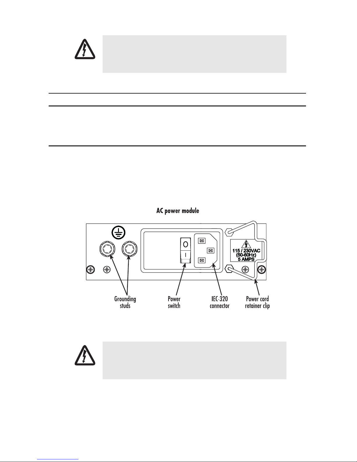
2.1 Installing the power cables—AC unit
This section describes installing the power cables into the IEC-320 connectors on the chassis power supply. Do
not connect the remaining end of the power cables to the power outlet at this time. Do the follow-
ing:
1. Install a power cable into an IEC-320 connector (see figure 1). The AC main socket outlet shall be within
3 meters of the equipment and shall be easily accessible.
Figure 1. IEC-320 connector and grounding stud locations
To avoid the risk of injury from electric shock, the power cords connected
to the IEC-320 connectors must be grounded power cords.
WARNING
2. Rotate the power cable retainer clip (see figure 1) so it secures the power cable plug in the
IEC-320 connector.
Visuality™ MVAS Quick Start Guide 3
 Loading...