

Page 1

TrinityAE Release 2.4.x
Administrator’s Reference Guide
Sales Office: +1 (301) 975-1000
Technical Support: +1 (301) 975-1007
E-mail: support@patton.com
WWW: www.patton.com
Document Number: 13223U3-001 Rev. B
Part Number: 07MTRINITY-ARG
Revised: April 11, 2008
Page 2

Patton Electronics Company, Inc.
7622 Rickenbacker Drive
Gaithersburg, MD 20879 USA
tel: +1 (301) 975-1000
fax: +1 (301) 869-9293
support: +1 (301) 975-1007
web: www.patton.com
e-mail: support@patton.com
Copyright
Copyright © 2008, Patton Electronics Company. All rights reserved.
Notice
The information in this document is subject to change without notice. Patton
Electronics assumes no liability for errors that may appear in this document.
The software described in this document is furnished under a license and may
be used or copied only in accordance with the terms of such license.
Supported Models
2884 2888
6081RC 3224
Software Versions 2.4.14 and earlier
Page 3

Summary Table of Contents
1 Introduction.................................................................................................................................................. 16
2 Tools ............................................................................................................................................................. 18
3 Authentication............................................................................................................................................... 25
4 Logging Management.................................................................................................................................... 32
5 SNMP Configuration .................................................................................................................................... 38
6 Interface Status.............................................................................................................................................. 44
7 IP Address Configuration.............................................................................................................................. 49
8 VLAN Configuration..................................................................................................................................... 56
9 Bridge Group Configuration......................................................................................................................... 62
10 T1/E1 Configuration..................................................................................................................................... 72
11 PPP Configuration........................................................................................................................................ 81
12 HDLC Configuration.................................................................................................................................... 94
13 ARP Table Management................................................................................................................................98
14 DHCP Server Configuration....................................................................................................................... 103
15 NAT and Port Forwarding .......................................................................................................................... 109
16 Route Configuration ................................................................................................................................... 121
17 RIP Configuration ...................................................................................................................................... 127
18 Quality of Service (QoS) ............................................................................................................................. 136
19 Ingress Traffic Management (ACL)............................................................................................................. 144
20 DSL Configuration ..................................................................................................................................... 153
21 System Clocking.......................................................................................................................................... 157
22 Contacting Patton for assistance ................................................................................................................. 162
3
Page 4

Table of Contents
Audience............................................................................................................................................................... 15
Structure............................................................................................................................................................... 15
1 Introduction.................................................................................................................................................. 16
Software Overview.................................................................................................................................................17
Getting Started with the WMI ..............................................................................................................................17
Logging in .......................................................................................................................................................17
Menu Structure ...............................................................................................................................................17
2 Tools ............................................................................................................................................................. 18
Overview ...............................................................................................................................................................19
Web Management Interface (WMI) ......................................................................................................................20
Import/Export ................................................................................................................................................20
Software Upgrade ...........................................................................................................................................20
Command Line Interface (CLI).............................................................................................................................21
Import/Export Commands .............................................................................................................................21
Show Commands ......................................................................................................................................21
Copy Command .......................................................................................................................................21
System Boot ..............................................................................................................................................21
Software Upgrade Commands ........................................................................................................................22
Software Upgrade Command ....................................................................................................................22
Show System Image Command .................................................................................................................22
System Image Command ..........................................................................................................................23
CLI Tools .......................................................................................................................................................24
Ping .........................................................................................................................................................24
Traceroute ................................................................................................................................................24
Reload ......................................................................................................................................................24
3 Authentication............................................................................................................................................... 25
Overview ...............................................................................................................................................................26
Configuration Overview .................................................................................................................................26
Web Management Interface (WMI) ......................................................................................................................27
Adding New Users ..........................................................................................................................................27
Deleting Users ................................................................................................................................................28
Changing Passwords .......................................................................................................................................28
Command Line Interface (CLI).............................................................................................................................29
Root Mode .....................................................................................................................................................29
Configuration Mode .......................................................................................................................................30
Debugging Information ..................................................................................................................................31
4 Logging Management.................................................................................................................................... 32
Overview ...............................................................................................................................................................33
Web Management Interface (WMI) ......................................................................................................................34
4
Page 5

5
TrinityAE Administrator’s Reference Guide
Table of Contents
Remote Log Configuration .............................................................................................................................34
Local Log Configuration .................................................................................................................................35
Log Definition Table ................................................................................................................................35
Local Log Viewer ............................................................................................................................................36
Command Line Interface (CLI).............................................................................................................................37
Logging Configuration Commands .................................................................................................................37
5 SNMP Configuration .................................................................................................................................... 38
Overview ...............................................................................................................................................................39
Configuration Overview .................................................................................................................................39
Web Management Interface (WMI) ......................................................................................................................40
Configuring the Server ....................................................................................................................................41
Managing SNMP Communities (SNMPv1 and SNMPv2) .............................................................................41
Adding SNMP Communities ....................................................................................................................41
Deleting SNMP Communities ..................................................................................................................41
Managing SNMP Users (SNMPv3) ................................................................................................................42
Adding SNMP Users .................................................................................................................................42
Deleting SNMP Users ...............................................................................................................................42
Managing System Variables .............................................................................................................................42
Command Line Interface (CLI).............................................................................................................................43
SNMP commands ..........................................................................................................................................43
6 Interface Status.............................................................................................................................................. 44
Overview ...............................................................................................................................................................45
Web Management Interface (WMI) ......................................................................................................................46
Viewing Errors ................................................................................................................................................46
Editing Interfaces ............................................................................................................................................46
Command Line Interface (CLI).............................................................................................................................47
Root Mode .....................................................................................................................................................47
Configuration Mode .......................................................................................................................................48
7 IP Address Configuration.............................................................................................................................. 49
Overview ...............................................................................................................................................................50
Configuration Overview .................................................................................................................................50
Terms used with IP Interfaces ...................................................................................................................50
Web Management Interface (WMI) ......................................................................................................................52
Adding an IP Interface ....................................................................................................................................53
IP Configuration .............................................................................................................................................53
Adding a DHCP Client ..................................................................................................................................54
DHCP Configuration .....................................................................................................................................54
Command Line Interface (CLI).............................................................................................................................55
IP Interface Commands ..................................................................................................................................55
DHCP Client Commands ..............................................................................................................................55
8 VLAN Configuration..................................................................................................................................... 56
Overview ...............................................................................................................................................................57
Page 6

6
TrinityAE Administrator’s Reference Guide
Table of Contents
Configuration Overview .................................................................................................................................57
Web Management Interface (WMI) ......................................................................................................................58
Create VLAN ..................................................................................................................................................58
Manage VLAN Interfaces ................................................................................................................................58
Command Line Interface (CLI).............................................................................................................................59
VLAN Configuration Commands ...................................................................................................................59
VLAN Configuration Example .................................................................................................................59
Show VLAN Information ...............................................................................................................................60
9 Bridge Group Configuration......................................................................................................................... 62
Overview ...............................................................................................................................................................63
Configuration Overview .................................................................................................................................63
Web Management Interface (WMI) ......................................................................................................................65
Bridge Group Configuration ...........................................................................................................................66
Add/Configure Bridge Groups ..................................................................................................................66
Delete Bridge Groups ................................................................................................................................66
Manage Interfaces .....................................................................................................................................66
STP Configuration .........................................................................................................................................67
Set STP Parameters ...................................................................................................................................67
Set STP Forwarding ..................................................................................................................................67
Show STP Status Information ...................................................................................................................67
Manage MAC Addresses .................................................................................................................................68
Display MAC Address Information ...........................................................................................................68
Add MAC Filter Rules ..............................................................................................................................68
Display/Delete MAC Filter Rules ..............................................................................................................68
Command Line Interface (CLI).............................................................................................................................69
Bridge Group Commands ...............................................................................................................................69
10 T1/E1 Configuration..................................................................................................................................... 72
Overview ...............................................................................................................................................................73
Configuration Overview .................................................................................................................................73
Web Management Interface (WMI) ......................................................................................................................74
Configure Clocking ........................................................................................................................................74
Manage Ports ..................................................................................................................................................74
Port Configuration ....................................................................................................................................75
Port Status ................................................................................................................................................76
Port History ..............................................................................................................................................76
Command Line Interface (CLI).............................................................................................................................77
Configuring the Clock Source .........................................................................................................................77
Selecting T1 or E1 Mode ................................................................................................................................77
Configuring T1 or E1 Applications .................................................................................................................77
Creating HDLC Channels ..............................................................................................................................78
Showing Configuration and Status ..................................................................................................................79
Clearing Errors and Performance History .......................................................................................................80
Using Test Modes ...........................................................................................................................................80
Page 7

7
TrinityAE Administrator’s Reference Guide
Table of Contents
11 PPP Configuration........................................................................................................................................ 81
Overview ...............................................................................................................................................................82
Configuration Overview .................................................................................................................................82
Web Management Interface (WMI) ......................................................................................................................83
Configure PPP Authentication ........................................................................................................................83
Add PPP Interfaces .........................................................................................................................................84
Status of PPP Interfaces .............................................................................................................................84
Delete PPP Interfaces ......................................................................................................................................84
Configure PPP Interfaces ................................................................................................................................85
Command Line Interface (CLI).............................................................................................................................87
PPP Authentication Commands .....................................................................................................................87
PPP Configuration Commands .......................................................................................................................87
Creating the interface ................................................................................................................................88
Configuring PPP negotiation ....................................................................................................................88
Enabling PPP on HDLC interfaces ...........................................................................................................89
Configuring LCP ......................................................................................................................................90
Configuring IPCP .....................................................................................................................................91
Configuring BCP ......................................................................................................................................92
Showing Configuration and Status ............................................................................................................93
Debugging Commands ...................................................................................................................................93
12 HDLC Configuration.................................................................................................................................... 94
Overview ...............................................................................................................................................................95
Configuration Overview .................................................................................................................................95
Web Management Interface (WMI) ......................................................................................................................96
Add/Delete HDLC Devices ............................................................................................................................96
Configure HDLC Devices ..............................................................................................................................96
Command Line Interface (CLI).............................................................................................................................97
HDLC Configuration Commands ..................................................................................................................97
HDLC Debugging Commands .......................................................................................................................97
13 ARP Table Management................................................................................................................................98
Overview ...............................................................................................................................................................99
Configuration Overview .................................................................................................................................99
About ARP Entries ....................................................................................................................................99
Web Management Interface (WMI) ....................................................................................................................100
Adding ARP Entries ......................................................................................................................................100
Deleting ARP Entries ....................................................................................................................................100
Command Line Interface (CLI)...........................................................................................................................101
Adding ARP Entries ......................................................................................................................................101
Deleting ARP Entries ....................................................................................................................................101
Displaying ARP Entries ................................................................................................................................101
14 DHCP Server Configuration....................................................................................................................... 103
Overview .............................................................................................................................................................104
Configuration Overview ...............................................................................................................................104
Page 8

8
TrinityAE Administrator’s Reference Guide
Table of Contents
Web Management Interface.................................................................................................................................105
Configuring the DHCP Server ......................................................................................................................105
Add/Delete Routers .................................................................................................................................106
Add/Delete DNSs ...................................................................................................................................106
Add/Delete Static Leases .........................................................................................................................106
Command Line Interface (CLI)...........................................................................................................................107
DHCP Server Configuration Commands .....................................................................................................107
DHCP Debugging Commands .....................................................................................................................108
15 NAT and Port Forwarding .......................................................................................................................... 109
Overview .............................................................................................................................................................110
Configuration Overview ...............................................................................................................................110
About NAT .............................................................................................................................................110
About Port Forwarding ...........................................................................................................................110
Web Management Interface (WMI) ....................................................................................................................111
NAPT ...........................................................................................................................................................111
Creating NAPT Profiles ..........................................................................................................................111
Deleting NAPT Profiles ..........................................................................................................................111
Editing NAPT Profiles ............................................................................................................................112
Port Forwarding ............................................................................................................................................113
Creating Port Forwarding Profiles ...........................................................................................................113
Deleting Port Forwarding Profiles ...........................................................................................................113
Editing Port Forwarding Profiles .............................................................................................................113
Connection Tracking ....................................................................................................................................114
Command Line Interface (CLI)...........................................................................................................................115
NAPT ...........................................................................................................................................................115
NAPT Configuration Commands ...........................................................................................................115
NAPT Profile Configuration Commands ................................................................................................115
NAPT CLI Examples ..............................................................................................................................116
Port Forwarding ............................................................................................................................................118
Port Forwarding Configuration Commands ............................................................................................118
Port Forwarding Profile Configuration Commands .................................................................................118
Port Forwarding CLI Examples ...............................................................................................................119
Connection Tracking ....................................................................................................................................120
Connection Tracking Configuration Commands ....................................................................................120
Connection Tracking CLI Examples .......................................................................................................120
16 Route Configuration ................................................................................................................................... 121
Overview .............................................................................................................................................................122
Configuration Overview ...............................................................................................................................122
About Flags .............................................................................................................................................122
Web Management Interface (WMI) ....................................................................................................................124
Adding a route ..............................................................................................................................................124
Deleting a route ............................................................................................................................................124
Command Line Interface (CLI)...........................................................................................................................125
Page 9

9
TrinityAE Administrator’s Reference Guide
Table of Contents
Adding a route ..............................................................................................................................................125
Deleting a route ............................................................................................................................................125
Displaying Routes .........................................................................................................................................126
17 RIP Configuration ...................................................................................................................................... 127
Overview .............................................................................................................................................................128
Configuration Overview ...............................................................................................................................128
About RIP Features .................................................................................................................................128
Web Management Interface (WMI) ....................................................................................................................130
Manage RIP ..................................................................................................................................................131
Route Redistribution ...............................................................................................................................131
Networks ................................................................................................................................................131
Neighbors ...............................................................................................................................................131
Timers .....................................................................................................................................................132
Passive Interfaces .....................................................................................................................................132
Configure Interface .......................................................................................................................................132
Command Line Interface (CLI)...........................................................................................................................133
Root Mode ...................................................................................................................................................133
Configuration Mode .....................................................................................................................................133
RIP Configuration Mode ..............................................................................................................................134
Interface Configuration Mode ......................................................................................................................135
18 Quality of Service (QoS) ............................................................................................................................. 136
Overview .............................................................................................................................................................137
Configuration Overview ...............................................................................................................................137
About QoS classes ...................................................................................................................................137
Web Management Interface (WMI) ....................................................................................................................139
QoS Profiles ..................................................................................................................................................139
Adding Qos Profiles ................................................................................................................................139
Deleting QoS Profiles ..............................................................................................................................139
Cloning QoS Profiles ..............................................................................................................................140
QoS Classes ..................................................................................................................................................140
Adding QoS Classes ................................................................................................................................140
Displaying/Deleting QoS Classes ............................................................................................................141
Manage Interfaces .........................................................................................................................................141
Command Line Interface (CLI)...........................................................................................................................142
QoS Configuration Commands ....................................................................................................................142
Show traffic classes of a profile ......................................................................................................................143
Show QoS configuration ...............................................................................................................................143
19 Ingress Traffic Management (ACL)............................................................................................................. 144
Overview .............................................................................................................................................................145
Configuration Overview ...............................................................................................................................145
About packet actions ...............................................................................................................................145
About packet matches .............................................................................................................................146
Web Management Interface (WMI) ....................................................................................................................147
Page 10

10
TrinityAE Administrator’s Reference Guide
Table of Contents
Access Control Profiles .................................................................................................................................148
Adding Access Control Profile .................................................................................................................148
Cloning Access Control Profiles ..............................................................................................................148
Deleting Access Control Profiles .............................................................................................................148
Adding Policing Rules .............................................................................................................................148
Manage Policing Rules ............................................................................................................................149
Access Control Rules .....................................................................................................................................149
Adding Access Control Rules ..................................................................................................................149
Displaying and Deleting Access Control Rules ........................................................................................150
Manage Interfaces .........................................................................................................................................150
Command Line Interface (CLI)...........................................................................................................................151
ACL Configuration Commands ....................................................................................................................151
Show access control rules of a profile .............................................................................................................152
Show ACL configuration ..............................................................................................................................152
20 DSL Configuration ..................................................................................................................................... 153
Overview .............................................................................................................................................................154
Configuration Overview ...............................................................................................................................154
Command Line Interface (CLI)...........................................................................................................................155
Viewing Statistical Information .....................................................................................................................155
DSL Configuration Example .........................................................................................................................156
21 System Clocking.......................................................................................................................................... 157
Overview .............................................................................................................................................................158
Configuration Overview ...............................................................................................................................158
Web Management Interface (WMI) ....................................................................................................................159
Configuring System Clocking .......................................................................................................................159
Managing Status ...........................................................................................................................................160
Command Line Interface (CLI)...........................................................................................................................161
System Clocking Commands ........................................................................................................................161
22 Contacting Patton for assistance ................................................................................................................. 162
Introduction........................................................................................................................................................163
Contact information............................................................................................................................................163
Warranty Service and Returned Merchandise Authorizations (RMAs).................................................................163
Warranty coverage ........................................................................................................................................163
Out-of-warranty service ...........................................................................................................................163
Returns for credit ....................................................................................................................................163
Return for credit policy ...........................................................................................................................164
RMA numbers ..............................................................................................................................................164
Shipping instructions ..............................................................................................................................164
Page 11

List of Figures
1 WMI Menu Structure . . . . . . . . . . . . . . . . . . . . . . . . . . . . . . . . . . . . . . . . . . . . . . . . . . . . . . . . . . . . . . . . . . . . 17
2 Import/Export . . . . . . . . . . . . . . . . . . . . . . . . . . . . . . . . . . . . . . . . . . . . . . . . . . . . . . . . . . . . . . . . . . . . . . . . . 20
3 Software Upgrade . . . . . . . . . . . . . . . . . . . . . . . . . . . . . . . . . . . . . . . . . . . . . . . . . . . . . . . . . . . . . . . . . . . . . . . 20
4 Authentication main page . . . . . . . . . . . . . . . . . . . . . . . . . . . . . . . . . . . . . . . . . . . . . . . . . . . . . . . . . . . . . . . . . 27
5 Add a new user . . . . . . . . . . . . . . . . . . . . . . . . . . . . . . . . . . . . . . . . . . . . . . . . . . . . . . . . . . . . . . . . . . . . . . . . . 27
6 Deleting a user . . . . . . . . . . . . . . . . . . . . . . . . . . . . . . . . . . . . . . . . . . . . . . . . . . . . . . . . . . . . . . . . . . . . . . . . . 28
7 Change Passwords . . . . . . . . . . . . . . . . . . . . . . . . . . . . . . . . . . . . . . . . . . . . . . . . . . . . . . . . . . . . . . . . . . . . . . . 28
8 Authentication - CLI . . . . . . . . . . . . . . . . . . . . . . . . . . . . . . . . . . . . . . . . . . . . . . . . . . . . . . . . . . . . . . . . . . . . 31
9 Logging Management main page . . . . . . . . . . . . . . . . . . . . . . . . . . . . . . . . . . . . . . . . . . . . . . . . . . . . . . . . . . . 34
10 Local Log Definition . . . . . . . . . . . . . . . . . . . . . . . . . . . . . . . . . . . . . . . . . . . . . . . . . . . . . . . . . . . . . . . . . . . . 35
11 Local Log Viewer . . . . . . . . . . . . . . . . . . . . . . . . . . . . . . . . . . . . . . . . . . . . . . . . . . . . . . . . . . . . . . . . . . . . . . . 36
12 SNMP main page . . . . . . . . . . . . . . . . . . . . . . . . . . . . . . . . . . . . . . . . . . . . . . . . . . . . . . . . . . . . . . . . . . . . . . . 40
13 SNMP Communities . . . . . . . . . . . . . . . . . . . . . . . . . . . . . . . . . . . . . . . . . . . . . . . . . . . . . . . . . . . . . . . . . . . . 41
14 SNMP Users . . . . . . . . . . . . . . . . . . . . . . . . . . . . . . . . . . . . . . . . . . . . . . . . . . . . . . . . . . . . . . . . . . . . . . . . . . . 42
15 System Variables . . . . . . . . . . . . . . . . . . . . . . . . . . . . . . . . . . . . . . . . . . . . . . . . . . . . . . . . . . . . . . . . . . . . . . . . 42
16 Interface Status main page . . . . . . . . . . . . . . . . . . . . . . . . . . . . . . . . . . . . . . . . . . . . . . . . . . . . . . . . . . . . . . . . 46
17 Editing an Ethernet interface from the status page . . . . . . . . . . . . . . . . . . . . . . . . . . . . . . . . . . . . . . . . . . . . . . 46
18 IP Address Configuration main page . . . . . . . . . . . . . . . . . . . . . . . . . . . . . . . . . . . . . . . . . . . . . . . . . . . . . . . . . 52
19 Adding an IP interface . . . . . . . . . . . . . . . . . . . . . . . . . . . . . . . . . . . . . . . . . . . . . . . . . . . . . . . . . . . . . . . . . . . 53
20 IP Configuration . . . . . . . . . . . . . . . . . . . . . . . . . . . . . . . . . . . . . . . . . . . . . . . . . . . . . . . . . . . . . . . . . . . . . . . 53
21 Adding a DHCP client . . . . . . . . . . . . . . . . . . . . . . . . . . . . . . . . . . . . . . . . . . . . . . . . . . . . . . . . . . . . . . . . . . . 54
22 DHCP configuration . . . . . . . . . . . . . . . . . . . . . . . . . . . . . . . . . . . . . . . . . . . . . . . . . . . . . . . . . . . . . . . . . . . . 54
23 VLAN Configuration main page . . . . . . . . . . . . . . . . . . . . . . . . . . . . . . . . . . . . . . . . . . . . . . . . . . . . . . . . . . . . 58
24 Create VLAN . . . . . . . . . . . . . . . . . . . . . . . . . . . . . . . . . . . . . . . . . . . . . . . . . . . . . . . . . . . . . . . . . . . . . . . . . . 58
25 VLAN Interfaces . . . . . . . . . . . . . . . . . . . . . . . . . . . . . . . . . . . . . . . . . . . . . . . . . . . . . . . . . . . . . . . . . . . . . . . . 58
26 Bridge Group Configuration main page . . . . . . . . . . . . . . . . . . . . . . . . . . . . . . . . . . . . . . . . . . . . . . . . . . . . . . 65
27 Managing interfaces . . . . . . . . . . . . . . . . . . . . . . . . . . . . . . . . . . . . . . . . . . . . . . . . . . . . . . . . . . . . . . . . . . . . . 66
28 STP Configuration . . . . . . . . . . . . . . . . . . . . . . . . . . . . . . . . . . . . . . . . . . . . . . . . . . . . . . . . . . . . . . . . . . . . . . 67
29 Displaying MAC address information . . . . . . . . . . . . . . . . . . . . . . . . . . . . . . . . . . . . . . . . . . . . . . . . . . . . . . . . 68
30 Configuring MAC filter rules . . . . . . . . . . . . . . . . . . . . . . . . . . . . . . . . . . . . . . . . . . . . . . . . . . . . . . . . . . . . . . 68
31 Show MAC address forwarding database . . . . . . . . . . . . . . . . . . . . . . . . . . . . . . . . . . . . . . . . . . . . . . . . . . . . . 70
32 Show STP configuration . . . . . . . . . . . . . . . . . . . . . . . . . . . . . . . . . . . . . . . . . . . . . . . . . . . . . . . . . . . . . . . . . . 70
33 Configure and show MAC filter information . . . . . . . . . . . . . . . . . . . . . . . . . . . . . . . . . . . . . . . . . . . . . . . . . . 71
34 Show interface configuration . . . . . . . . . . . . . . . . . . . . . . . . . . . . . . . . . . . . . . . . . . . . . . . . . . . . . . . . . . . . . . 71
35 T1/E1 Configuration screen . . . . . . . . . . . . . . . . . . . . . . . . . . . . . . . . . . . . . . . . . . . . . . . . . . . . . . . . . . . . . . . 74
36 T1/E1 Port Configuration Settings . . . . . . . . . . . . . . . . . . . . . . . . . . . . . . . . . . . . . . . . . . . . . . . . . . . . . . . . . . 75
37 Adding and Deleting HDLC Channels . . . . . . . . . . . . . . . . . . . . . . . . . . . . . . . . . . . . . . . . . . . . . . . . . . . . . . . 76
38 Port Status . . . . . . . . . . . . . . . . . . . . . . . . . . . . . . . . . . . . . . . . . . . . . . . . . . . . . . . . . . . . . . . . . . . . . . . . . . . . 76
39 Port History . . . . . . . . . . . . . . . . . . . . . . . . . . . . . . . . . . . . . . . . . . . . . . . . . . . . . . . . . . . . . . . . . . . . . . . . . . . 76
40 PPP Authentication Configuration . . . . . . . . . . . . . . . . . . . . . . . . . . . . . . . . . . . . . . . . . . . . . . . . . . . . . . . . . . 83
41 Add/Delete PPP Interfaces . . . . . . . . . . . . . . . . . . . . . . . . . . . . . . . . . . . . . . . . . . . . . . . . . . . . . . . . . . . . . . . . 84
42 Configuring a PPP interface . . . . . . . . . . . . . . . . . . . . . . . . . . . . . . . . . . . . . . . . . . . . . . . . . . . . . . . . . . . . . . . 85
43 HDLC Devices main page . . . . . . . . . . . . . . . . . . . . . . . . . . . . . . . . . . . . . . . . . . . . . . . . . . . . . . . . . . . . . . . . 96
44 Add/Delete H.110 Maps . . . . . . . . . . . . . . . . . . . . . . . . . . . . . . . . . . . . . . . . . . . . . . . . . . . . . . . . . . . . . . . . . 96
45 ARP main page . . . . . . . . . . . . . . . . . . . . . . . . . . . . . . . . . . . . . . . . . . . . . . . . . . . . . . . . . . . . . . . . . . . . . . . . 100
46 Deleting an ARP entry from the ARP table . . . . . . . . . . . . . . . . . . . . . . . . . . . . . . . . . . . . . . . . . . . . . . . . . . . 100
47 Command Line Interface "show arp" command . . . . . . . . . . . . . . . . . . . . . . . . . . . . . . . . . . . . . . . . . . . . . . . 102
11
Page 12

12
TrinityAE Administrator’s Reference Guide
48 DHCP Server Configuraion Main Screen . . . . . . . . . . . . . . . . . . . . . . . . . . . . . . . . . . . . . . . . . . . . . . . . . . . . 105
49 NAT Configuraion . . . . . . . . . . . . . . . . . . . . . . . . . . . . . . . . . . . . . . . . . . . . . . . . . . . . . . . . . . . . . . . . . . . . . 111
50 NAT Profile Configuration . . . . . . . . . . . . . . . . . . . . . . . . . . . . . . . . . . . . . . . . . . . . . . . . . . . . . . . . . . . . . . . 112
51 Main Port Forwarding Configuration . . . . . . . . . . . . . . . . . . . . . . . . . . . . . . . . . . . . . . . . . . . . . . . . . . . . . . . 113
52 Port Forwarding Profile Configuration . . . . . . . . . . . . . . . . . . . . . . . . . . . . . . . . . . . . . . . . . . . . . . . . . . . . . . 113
53 Connection Tracking Configuration . . . . . . . . . . . . . . . . . . . . . . . . . . . . . . . . . . . . . . . . . . . . . . . . . . . . . . . . 114
54 Route Configuration main page . . . . . . . . . . . . . . . . . . . . . . . . . . . . . . . . . . . . . . . . . . . . . . . . . . . . . . . . . . . 124
55 Route Configuration Flags . . . . . . . . . . . . . . . . . . . . . . . . . . . . . . . . . . . . . . . . . . . . . . . . . . . . . . . . . . . . . . . 124
56 Command Line Interface "show route" command . . . . . . . . . . . . . . . . . . . . . . . . . . . . . . . . . . . . . . . . . . . . . 126
57 RIP Configuration . . . . . . . . . . . . . . . . . . . . . . . . . . . . . . . . . . . . . . . . . . . . . . . . . . . . . . . . . . . . . . . . . . . . . 130
58 Configure Interface . . . . . . . . . . . . . . . . . . . . . . . . . . . . . . . . . . . . . . . . . . . . . . . . . . . . . . . . . . . . . . . . . . . . . 132
59 QoS main page . . . . . . . . . . . . . . . . . . . . . . . . . . . . . . . . . . . . . . . . . . . . . . . . . . . . . . . . . . . . . . . . . . . . . . . . 139
60 QoS Classes . . . . . . . . . . . . . . . . . . . . . . . . . . . . . . . . . . . . . . . . . . . . . . . . . . . . . . . . . . . . . . . . . . . . . . . . . . 140
61 Manage Interfaces . . . . . . . . . . . . . . . . . . . . . . . . . . . . . . . . . . . . . . . . . . . . . . . . . . . . . . . . . . . . . . . . . . . . . . 141
62 Show traffic classes of a profile . . . . . . . . . . . . . . . . . . . . . . . . . . . . . . . . . . . . . . . . . . . . . . . . . . . . . . . . . . . . 143
63 Show QoS configuration . . . . . . . . . . . . . . . . . . . . . . . . . . . . . . . . . . . . . . . . . . . . . . . . . . . . . . . . . . . . . . . . . 143
64 Ingress Traffic Management main page . . . . . . . . . . . . . . . . . . . . . . . . . . . . . . . . . . . . . . . . . . . . . . . . . . . . . . 147
65 Managing Access Control Profiles . . . . . . . . . . . . . . . . . . . . . . . . . . . . . . . . . . . . . . . . . . . . . . . . . . . . . . . . . . 148
66 Managing ACL rules . . . . . . . . . . . . . . . . . . . . . . . . . . . . . . . . . . . . . . . . . . . . . . . . . . . . . . . . . . . . . . . . . . . . 149
67 Managing interfaces . . . . . . . . . . . . . . . . . . . . . . . . . . . . . . . . . . . . . . . . . . . . . . . . . . . . . . . . . . . . . . . . . . . . 150
68 Show access control rules of a profile . . . . . . . . . . . . . . . . . . . . . . . . . . . . . . . . . . . . . . . . . . . . . . . . . . . . . . . 152
69 Show ACL configuration . . . . . . . . . . . . . . . . . . . . . . . . . . . . . . . . . . . . . . . . . . . . . . . . . . . . . . . . . . . . . . . . 152
70 Configuring system clocking . . . . . . . . . . . . . . . . . . . . . . . . . . . . . . . . . . . . . . . . . . . . . . . . . . . . . . . . . . . . . . 159
71 Managing clock status . . . . . . . . . . . . . . . . . . . . . . . . . . . . . . . . . . . . . . . . . . . . . . . . . . . . . . . . . . . . . . . . . . . 160
Page 13

List of Tables
1 Show Import/Export - CLI Commands . . . . . . . . . . . . . . . . . . . . . . . . . . . . . . . . . . . . . . . . . . . . . . . . . . . . . . 21
2 Copy Import/Export - CLI Commands . . . . . . . . . . . . . . . . . . . . . . . . . . . . . . . . . . . . . . . . . . . . . . . . . . . . . . 21
3 Software Upgrade - CLI Command . . . . . . . . . . . . . . . . . . . . . . . . . . . . . . . . . . . . . . . . . . . . . . . . . . . . . . . . . 22
4 Show System Image - CLI Command . . . . . . . . . . . . . . . . . . . . . . . . . . . . . . . . . . . . . . . . . . . . . . . . . . . . . . . . 22
5 System Image - CLI Command . . . . . . . . . . . . . . . . . . . . . . . . . . . . . . . . . . . . . . . . . . . . . . . . . . . . . . . . . . . . 23
6 Ping - CLI Command . . . . . . . . . . . . . . . . . . . . . . . . . . . . . . . . . . . . . . . . . . . . . . . . . . . . . . . . . . . . . . . . . . . . 24
7 Traceroute - CLI Command . . . . . . . . . . . . . . . . . . . . . . . . . . . . . . . . . . . . . . . . . . . . . . . . . . . . . . . . . . . . . . . 24
8 Reload - CLI Command . . . . . . . . . . . . . . . . . . . . . . . . . . . . . . . . . . . . . . . . . . . . . . . . . . . . . . . . . . . . . . . . . . 24
9 Authentication Root Mode - CLI Commands . . . . . . . . . . . . . . . . . . . . . . . . . . . . . . . . . . . . . . . . . . . . . . . . . 29
10 Authentication Configuration Mode - CLI Commands . . . . . . . . . . . . . . . . . . . . . . . . . . . . . . . . . . . . . . . . . . 30
11 Logging - CLI Commands . . . . . . . . . . . . . . . . . . . . . . . . . . . . . . . . . . . . . . . . . . . . . . . . . . . . . . . . . . . . . . . . 37
12 SNMP - CLI Commands . . . . . . . . . . . . . . . . . . . . . . . . . . . . . . . . . . . . . . . . . . . . . . . . . . . . . . . . . . . . . . . . . 43
13 Interface Root Mode - CLI Commands . . . . . . . . . . . . . . . . . . . . . . . . . . . . . . . . . . . . . . . . . . . . . . . . . . . . . . 47
14 Interface Configuration Mode - CLI Commands . . . . . . . . . . . . . . . . . . . . . . . . . . . . . . . . . . . . . . . . . . . . . . . 48
15 IP Interface - CLI Commands . . . . . . . . . . . . . . . . . . . . . . . . . . . . . . . . . . . . . . . . . . . . . . . . . . . . . . . . . . . . . 55
16 DHCP client - CLI Commands . . . . . . . . . . . . . . . . . . . . . . . . . . . . . . . . . . . . . . . . . . . . . . . . . . . . . . . . . . . . 55
17 VLAN - CLI Commands . . . . . . . . . . . . . . . . . . . . . . . . . . . . . . . . . . . . . . . . . . . . . . . . . . . . . . . . . . . . . . . . . 59
18 Show VLAN Information - CLI Commands . . . . . . . . . . . . . . . . . . . . . . . . . . . . . . . . . . . . . . . . . . . . . . . . . . 60
19 Bridge Group Configuration - CLI Commands . . . . . . . . . . . . . . . . . . . . . . . . . . . . . . . . . . . . . . . . . . . . . . . . 69
20 T1/E1 - Clock Source - CLI Commands . . . . . . . . . . . . . . . . . . . . . . . . . . . . . . . . . . . . . . . . . . . . . . . . . . . . . 77
21 T1/E1 - Mode - CLI Commands . . . . . . . . . . . . . . . . . . . . . . . . . . . . . . . . . . . . . . . . . . . . . . . . . . . . . . . . . . . 77
22 T1/E1 - Applications - CLI Commands . . . . . . . . . . . . . . . . . . . . . . . . . . . . . . . . . . . . . . . . . . . . . . . . . . . . . . 77
23 T1/E1 - HDLC Channels - CLI Command . . . . . . . . . . . . . . . . . . . . . . . . . . . . . . . . . . . . . . . . . . . . . . . . . . . 78
24 T1/E1 - Show Configuration & Status - CLI Command . . . . . . . . . . . . . . . . . . . . . . . . . . . . . . . . . . . . . . . . . 79
25 T1/E1 - Clearing Errors - CLI Command . . . . . . . . . . . . . . . . . . . . . . . . . . . . . . . . . . . . . . . . . . . . . . . . . . . . 80
26 T1/E1 - Test Modes - CLI Command . . . . . . . . . . . . . . . . . . . . . . . . . . . . . . . . . . . . . . . . . . . . . . . . . . . . . . . 80
27 Steps for Configuring PPP Authentication - CLI . . . . . . . . . . . . . . . . . . . . . . . . . . . . . . . . . . . . . . . . . . . . . . . 87
28 Steps for Creating a PPP Interface - CLI . . . . . . . . . . . . . . . . . . . . . . . . . . . . . . . . . . . . . . . . . . . . . . . . . . . . . . 88
29 Steps for Configuring PPP Negotiation - CLI . . . . . . . . . . . . . . . . . . . . . . . . . . . . . . . . . . . . . . . . . . . . . . . . . . 88
30 Steps for Enabling PPP on HDLC interfaces - CLI . . . . . . . . . . . . . . . . . . . . . . . . . . . . . . . . . . . . . . . . . . . . . . 89
31 Steps for Configuring LCP - CLI . . . . . . . . . . . . . . . . . . . . . . . . . . . . . . . . . . . . . . . . . . . . . . . . . . . . . . . . . . . 90
32 Steps for Configuring IPCP - CLI . . . . . . . . . . . . . . . . . . . . . . . . . . . . . . . . . . . . . . . . . . . . . . . . . . . . . . . . . . 91
33 Steps for Configuring BCP - CLI . . . . . . . . . . . . . . . . . . . . . . . . . . . . . . . . . . . . . . . . . . . . . . . . . . . . . . . . . . . 92
34 Showing PPP Configuration and Status . . . . . . . . . . . . . . . . . . . . . . . . . . . . . . . . . . . . . . . . . . . . . . . . . . . . . . 93
35 PPP Debugging Commands - CLI . . . . . . . . . . . . . . . . . . . . . . . . . . . . . . . . . . . . . . . . . . . . . . . . . . . . . . . . . . 93
36 Steps for Creating/Configuring HDLC Devices - CLI . . . . . . . . . . . . . . . . . . . . . . . . . . . . . . . . . . . . . . . . . . . 97
37 HDLC Debugging - CLI . . . . . . . . . . . . . . . . . . . . . . . . . . . . . . . . . . . . . . . . . . . . . . . . . . . . . . . . . . . . . . . . . 97
38 ARP - CLI . . . . . . . . . . . . . . . . . . . . . . . . . . . . . . . . . . . . . . . . . . . . . . . . . . . . . . . . . . . . . . . . . . . . . . . . . . . 101
39 Adding ARP Entries - CLI . . . . . . . . . . . . . . . . . . . . . . . . . . . . . . . . . . . . . . . . . . . . . . . . . . . . . . . . . . . . . . . 101
40 Deleting ARP Entries - CLI . . . . . . . . . . . . . . . . . . . . . . . . . . . . . . . . . . . . . . . . . . . . . . . . . . . . . . . . . . . . . . 101
41 Showing ARP Entries - CLI . . . . . . . . . . . . . . . . . . . . . . . . . . . . . . . . . . . . . . . . . . . . . . . . . . . . . . . . . . . . . . 101
42 DHCP Server - CLI Commands . . . . . . . . . . . . . . . . . . . . . . . . . . . . . . . . . . . . . . . . . . . . . . . . . . . . . . . . . . . 107
43 DHCP Debugging - CLI . . . . . . . . . . . . . . . . . . . . . . . . . . . . . . . . . . . . . . . . . . . . . . . . . . . . . . . . . . . . . . . . 108
13
Page 14

14
TrinityAE Administrator’s Reference Guide
44 NAT Configuration - CLI Commands . . . . . . . . . . . . . . . . . . . . . . . . . . . . . . . . . . . . . . . . . . . . . . . . . . . . . . 115
45 NAT Profile Configuration - CLI Commands . . . . . . . . . . . . . . . . . . . . . . . . . . . . . . . . . . . . . . . . . . . . . . . . 115
46 Port Forwarding Configuration - CLI Commands . . . . . . . . . . . . . . . . . . . . . . . . . . . . . . . . . . . . . . . . . . . . . 118
47 Port Forwarding Profile Configuration - CLI Commands . . . . . . . . . . . . . . . . . . . . . . . . . . . . . . . . . . . . . . . 118
48 Connection Tracking Configuration - CLI Commands . . . . . . . . . . . . . . . . . . . . . . . . . . . . . . . . . . . . . . . . . 120
49 Route Configuration - CLI Commands . . . . . . . . . . . . . . . . . . . . . . . . . . . . . . . . . . . . . . . . . . . . . . . . . . . . . 125
50 Showing Routes - CLI . . . . . . . . . . . . . . . . . . . . . . . . . . . . . . . . . . . . . . . . . . . . . . . . . . . . . . . . . . . . . . . . . . 126
51 RIP Root Mode - CLI Command . . . . . . . . . . . . . . . . . . . . . . . . . . . . . . . . . . . . . . . . . . . . . . . . . . . . . . . . . . 133
52 RIP Configuration Mode - CLI Command . . . . . . . . . . . . . . . . . . . . . . . . . . . . . . . . . . . . . . . . . . . . . . . . . . 133
53 RIP Configuration Mode - CLI Commands . . . . . . . . . . . . . . . . . . . . . . . . . . . . . . . . . . . . . . . . . . . . . . . . . . 134
54 RIP Interface Configuration Mode - CLI Commands . . . . . . . . . . . . . . . . . . . . . . . . . . . . . . . . . . . . . . . . . . 135
55 Match values for QoS . . . . . . . . . . . . . . . . . . . . . . . . . . . . . . . . . . . . . . . . . . . . . . . . . . . . . . . . . . . . . . . . . . . 138
56 QoS - CLI Commands . . . . . . . . . . . . . . . . . . . . . . . . . . . . . . . . . . . . . . . . . . . . . . . . . . . . . . . . . . . . . . . . . . 142
57 ACL - CLI Commands . . . . . . . . . . . . . . . . . . . . . . . . . . . . . . . . . . . . . . . . . . . . . . . . . . . . . . . . . . . . . . . . . . 151
58 DSL - CLI Commands . . . . . . . . . . . . . . . . . . . . . . . . . . . . . . . . . . . . . . . . . . . . . . . . . . . . . . . . . . . . . . . . . . 155
59 Steps for Configuring System Clocking - CLI Commands . . . . . . . . . . . . . . . . . . . . . . . . . . . . . . . . . . . . . . . 161
Page 15

About this guide
This TrinityAE Administrator’s Reference Guide describes how to configure components through both the Web
Management Interface (WMI) and the Command Line Interface (CLI) of Patton’s Trinity system.
For detailed hardware or set-up information, refer to the product’s Getting Started Guide .
Audience
This guide is intended for the following users:
• Operators
• Installers
• Maintenance technicians
Structure
This guide contains the following chapters and appendices:
• Chapter 1 on page 16 provides an overview about the software
• Chapter 2 on page 18 provides information on import/export. software upgrade, and special CLI features
• Chapter 3 on page 25 provides information on managing the authentication of users and privileges
• Chapter 4 on page 32 provides information on syslog functions
• Chapter 5 on page 38 provides information about configuring SNMP
• Chapter 6 on page 44 provides information on the status of interfaces
• Chapter 7 on page 49 provides information on IP commands
• Chapter 8 on page 56 provides information on managing VLANs
• Chapter 9 on page 62 provides information on configuring bridge groups
• Chapter 10 on page 72 provides information on configuring the T1/E1 interfaces
• Chapter 11 on page 81 provides information on configuring PPP
• Chapter 12 on page 94 provides information on configuring HDLC interfaces
• Chapter 13 on page 98 provides information on the ARP Table Management component
• Chapter 14 on page 103 provides information on configuring the DHCP server
• Chapter 15 on page 109 provides information on NAPT and Port Forwarding
• Chapter 16 on page 121 provides information on configuring the route table
• Chapter 17 on page 127 provides information on configuring RIP
• Chapter 18 on page 136 provides information on managing egress (QoS) traffic
• Chapter 19 on page 144 provides information on managing ingress (ACL) traffic
• Chapter 20 on page 153 provides information on configuring DSL
• Chapter 21 on page 157 provides information on system clocking
• Chapter 22 on page 162 provides information on contacting Patton for service and support
15
Page 16

Chapter 1
Chapter contents
Software Overview.................................................................................................................................................17
Getting Started with the WMI ..............................................................................................................................17
Logging in .......................................................................................................................................................17
Menu Structure ...............................................................................................................................................17
Introduction
16
Page 17
17
TrinityAE Administrator’s Reference Guide
1 • Introduction
Software Overview
This TrinityAE Administrator’s Reference Guide provides information about configuring the software for your
Trinity model. For information about setting up the unit, or for hardware specifications, refer to the Getting
Started Guide , located on the CD-ROM shipped with your product or on the web at www.patton.com.
Getting Started with the WMI
Logging in
To get started with the Web Management Interface (WMI), log into the unit using:
Username: admin
Password: <Leave blank.>
To add users, delete users, or set user privileges, see Chapter 3, “Authentication” on page 25.
Menu Structure
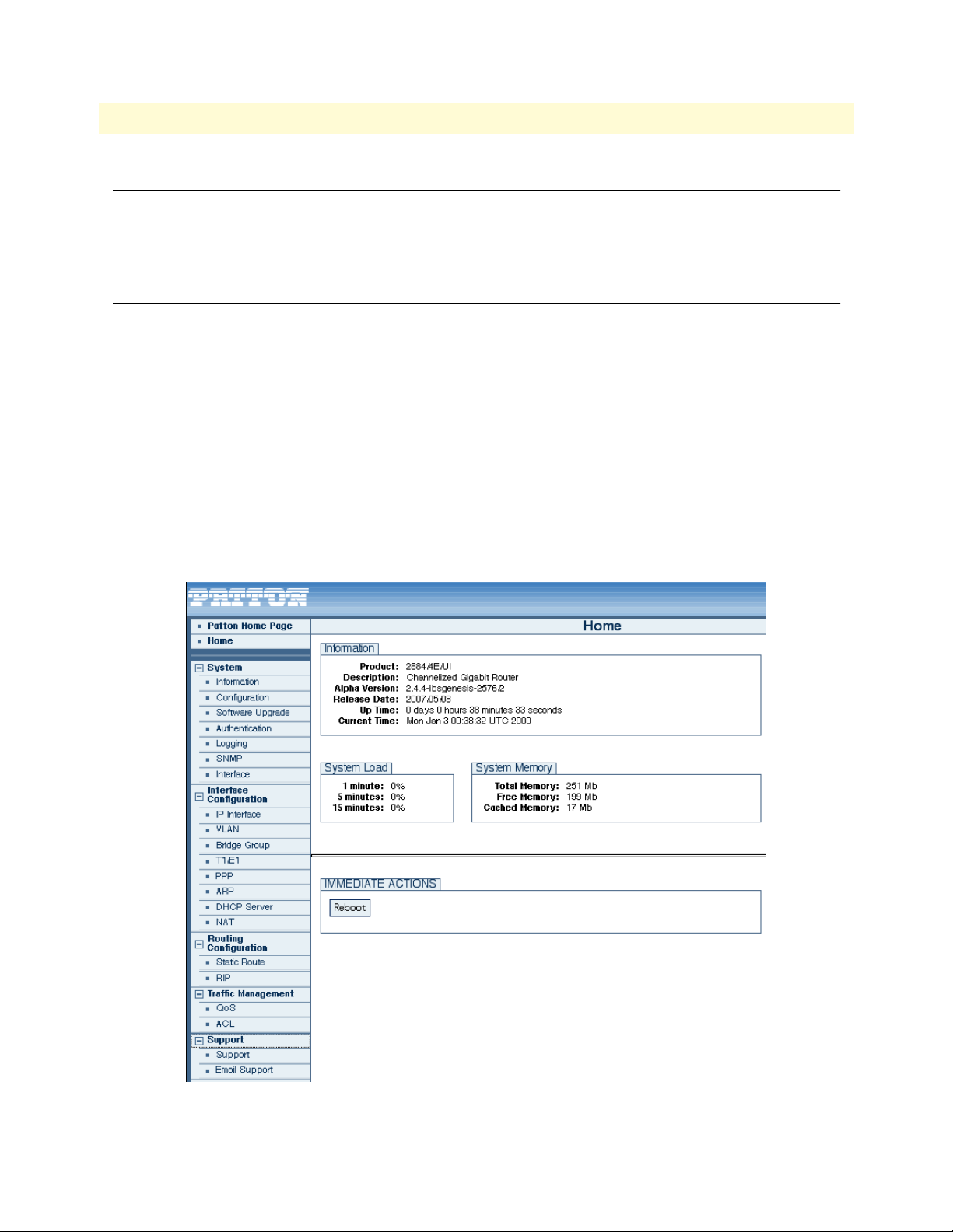
The main menu has the following options (figure 1)
Note
The main menu for your model may vary slightly from what is shown
figure 1.
in
Software Overview
Figure 1. WMI Menu Structure
Page 18

Chapter 2
Chapter contents
Overview ...............................................................................................................................................................19
Web Management Interface (WMI) ......................................................................................................................20
Import/Export ................................................................................................................................................20
Software Upgrade ...........................................................................................................................................20
Command Line Interface (CLI).............................................................................................................................21
Import/Export Commands .............................................................................................................................21
Show Commands ......................................................................................................................................21
Copy Command .......................................................................................................................................21
System Boot ..............................................................................................................................................21
Software Upgrade Commands ........................................................................................................................22
Software Upgrade Command ....................................................................................................................22
Show System Image Command .................................................................................................................22
System Image Command ..........................................................................................................................23
CLI Tools .......................................................................................................................................................24
Ping .........................................................................................................................................................24
Traceroute ................................................................................................................................................24
Reload ......................................................................................................................................................24
Tools
18
Page 19

19
TrinityAE Administrator’s Reference Guide
2 • Tools
Overview
This chapter describes the web management and configuration commands for importing/exporting configurations, upgrading the software, and other CLI tools, such as ping, traceroute, and reload.
Note
To import or export a configuration using the WMI, see “Import/Export” on page 20.
To import or export a configuration using the CLI, see “Import/Export Commands” on page 21.
To upgrade the software using the WMI, see “Software Upgrade” on page 20.
To upgrade the software using the CLI, see “Software Upgrade Commands” on page 22.
To ping an IP address, see “Ping” on page 24.
To trace the path of a route, see “Traceroute” on page 24.
To force the system to reboot, see “Reload” on page 24.
The menu, commands, and features for your model may vary slightly
from what is shown in this manual. Some models may not include all
of the features mentioned. Refer to the Getting Started Guide for your
device to see which features are available.
Overview
Page 20
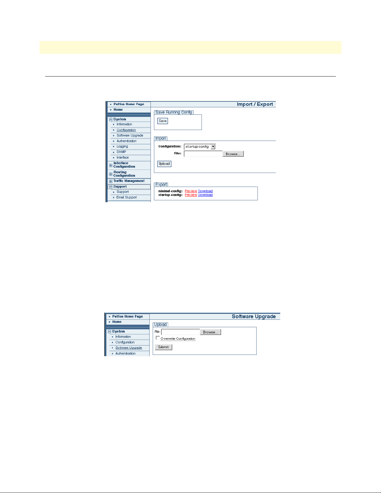
20
TrinityAE Administrator’s Reference Guide
Web Management Interface (WMI)
Import/Export
To access the Import/Export page, click on System > Configuration from the main menu.
Figure 2. Import/Export
To import a configuration, click Browse to find the configuration file to import, then click Upload.
2 • Tools
To export a configuration, click the Download link next to the configuration file under the Export section.
Software Upgrade
A unit's software image may be upgraded to a newer software version. New software versions are posted on the
Patton Electronics website as features are added and bugs are fixed. Both the web management interface and
the command line interface provide the functionality to upgrade the software
To access the Software Upgrade page, click on System > Software Upgrade from the main menu on the left of
the screen.
Figure 3. Software Upgrade
During the upgrade, the box will be unresponsive; the web server and telnet server will be shut down. When
the upgrade completes, the unit will automatically reboot into the new software and become operational again.
To upgrade the software, click the Browse button to select the software image file, then click Submit to start
the upgrade.
Note The software upgrade uses the *.tar file. Do not extract the contents
of this file.
Web Management Interface (WMI)
Page 21

TrinityAE Administrator’s Reference Guide 2 • Tools
Command Line Interface (CLI)
Import/Export Commands
The following commands describe how to print and copy configuration files using the CLI.
Show Commands
Table 1. Show Import/Export - CLI Commands
Command Explanation
Trinity# show shipping-config Prints the shipping configuration (static file).
Trinity# show running-config Prints the current system config (dynamically generated).
Trinity# show startup-config Prints the startup configuration (user-updated file).
Trinity# show minimal-config Prints the minimal configuration (static file).
Copy Command
Table 2. Copy Import/Export - CLI Commands
Command Explanation
Trinity# copy {running-config|shipping-config|minimal-config} startupconfig
Copies the contents of the minimal-config file or running configuration to the startup configuration file.
The startup configuration file will be read at the next boot.
System Boot
During the boot sequence, the contents of the startup configuration file will be applied to the system. Any
errors found in the configuration file will be reported, as shown in the example below:
Attempting to restore config from /flash/config/startup-config ...
Error Importing Line(12): Invalid Command!
[[ no enable test-server ]]
Command Line Interface (CLI) 21
Page 22

TrinityAE Administrator’s Reference Guide 2 • Tools
Software Upgrade Commands
Note The commands for your model may vary slightly from what is shown
in this manual. Some models may not include all of the features mentioned. Refer to the Getting Started Guide for your device to see which
features are available.
Software Upgrade Command
To perform a software upgrade from the CLI, there must be a TFTP server to which the unit has access. The
software image file must be placed on the TFTP server. The following command is available from the root
mode:
Table 3. Software Upgrade - CLI Command
Command Explanation
Trinity# copy tftp://<serverip>/<filename> {flash:|flash-cfg:}
This command starts the software upgrade. <serverip> is the
IP address of a TFTP server that contains the software image.
<filename> is the name of the software image file on the
TFTP server. If flash-cfg: is specified, the box will also be
restored to the factory default configuration.
The following is example output:
Transferring file...
Installing file...
0% 20% 40% 60% 80% 100%
+---------+---------+---------+---------+---------+
Box will be unresponsive until software upgrade is complete.
Trinity# Done. Rebooting in 5 seconds...
If using telnet, the connection will close after the file transfer and will not be available again until after the
upgrade has completed. Whether performed through the console or a telnet session, the unit will automatically
reboot and begin running the new software.
Show System Image Command
Table 4. Show System Image - CLI Command
Command Explanation
Trinity# show system image The image has been installed on the partition that is currently
inactive. This command shows which image is currently active
so that we can determine on which image the software was
installed.
The following is example output:
Command Line Interface (CLI) 22
Page 23

TrinityAE Administrator’s Reference Guide 2 • Tools
Image Overview
Number of Images: 2
Current Image: 1
Next Image: 1
Image #1
Image State: active
Load Date: Sun Feb 10 07:41:32 2030
Release Date: Thu May 10 14:53:03 2007
Image Name: hornet5261_full_image
Patton Version: 2.4.4
Image #2
Image State: inactive
Load Date: Tue Jan 22 11:25:29 2030
Release Date: Thu May 31 16:58:32 2007
Image Name: hornet5261_full_image
Patton Version: 2.4
System Image Command
Table 5. System Image - CLI Command
Command Explanation
Trinity[config]# system image {1|2} To begin using the software that was just installed, select the
system image that is currently inactive, and then reboot.
Note
• Only one software upgrade may be performed at a time. Other-
wise, the flash could be corrupted. Both the web interface and
command line interface will prevent concurrent upgrades.
• Some models may shut down several services during the upgrade
and cannot be counted on to function properly until after the software upgrade completes.
• The config partition is not affected by the software upgrade unless
specified by the user.
Command Line Interface (CLI) 23
Page 24

TrinityAE Administrator’s Reference Guide 2 • Tools
CLI Tools
Ping
Table 6. Ping - CLI Command
Command Explanation
Trinity# ping <ip address>
[<count>|continuous]
Trinity# ping 10.11.2.2
PING 10.11.2.2 (10.11.2.2): 56 data bytes
64 bytes from 10.11.2.2: icmp_seq=0 ttl=128 time=17.3 ms
64 bytes from 10.11.2.2: icmp_seq=1 ttl=128 time=3.1 ms
64 bytes from 10.11.2.2: icmp_seq=2 ttl=128 time=2.5 ms
64 bytes from 10.11.2.2: icmp_seq=3 ttl=128 time=3.3 ms
64 bytes from 10.11.2.2: icmp_seq=4 ttl=128 time=4.0 ms
--- 10.11.2.2 ping statistics ---
5 packets transmitted, 5 packets received, 0% packet loss
round-trip min/avg/max = 2.5/6.0/17.3 ms
Sends ICMP Echo requests to an ip address (broadcast address
accepted). The user can optionally specify a number of echo
requests to send, or send requests continuously.
(CTRL-C will cancel the command in progress.)
Traceroute
Table 7. Traceroute - CLI Command
Command Explanation
Trinity# traceroute <ip address> Traces the hops from the device to an Internet address.
(CTRL-C will cancel the command in progress.)
Trinity# traceroute 10.10.1.1
1 192.168.85.2 (192.168.85.2) 11.963 ms 1.024 ms 0.769 ms
2 10.11.2.1 (10.11.2.1) 3.01 ms 2.725 ms 2.434 ms
3 10.11.1.1 (10.11.1.1) 3.935 ms 1.585 ms 1.709 ms
4 10.10.1.1 (10.10.1.1) 3.528 ms * 5.536 ms
Reload
Table 8. Reload - CLI Command
Command Explanation
Trinity# reload [{in <seconds>|cancel}] Forces the system to reboot. The user can optionally delay the
reboot by a number of seconds or cancel a pending reboot.
Command Line Interface (CLI) 24
Page 25

Chapter 3 Authentication
Chapter contents
Overview ...............................................................................................................................................................26
Configuration Overview .................................................................................................................................26
Web Management Interface (WMI) ......................................................................................................................27
Adding New Users ..........................................................................................................................................27
Deleting Users ................................................................................................................................................28
Changing Passwords .......................................................................................................................................28
Command Line Interface (CLI).............................................................................................................................29
Root Mode .....................................................................................................................................................29
Configuration Mode .......................................................................................................................................30
Debugging Information ..................................................................................................................................31
25
Page 26

TrinityAE Administrator’s Reference Guide 3 • Authentication
Overview
This chapter describes how to specify the configuration settings for creating/deleting system users, setting user
privilege levels, and displaying existing users.
Note The menu, commands, and features for your model may vary slightly
from what is shown in this manual. Some models may not include all
of the features mentioned. Refer to the Getting Started Guide for your
device to see which features are available.
Configuration Overview
A new user can be added to the system through configuration of one or a combination of the following parameters:
• Username (required): The unique identifier for the user. It must be an alphanumeric string from the set of
characters [0-9a-zA-Z] with no spaces. The maximum allowed length is 32 characters.
• Password (optional): User password associated with the user account. It must be an alphanumeric string
from the set of characters [0-9a-zA-Z] with no spaces. The maximum allowed length is 32 characters. It is
possible to allow an empty password field by choosing the no password option from the Web GUI. In this
case, no password would be required for login.
• Privilege (required): The access group/level associated with the user account. Two user access groups are
provided:
- Superuser access group: Allows for read/write access to the system.
- Monitor access group: Allows for read-only access to the system.
• Description (optional): A short decription for the user account. This option is currently available through
the WMI only. The alphanumeric string can have a maximum length of 32 characters.
Users can be deleted from the system by specifying the username. Add/Delete user operations require superuser
or engineer access level. The show feature displays a list of the existing system users, their privilege level, and
the description field.
To configure Authentication through the WMI,
see the section “Web Management Interface (WMI)” on page 27.
To configure Authentication through the CLI,
see the section “Command Line Interface (CLI)” on page 29.
Overview 26
Page 27
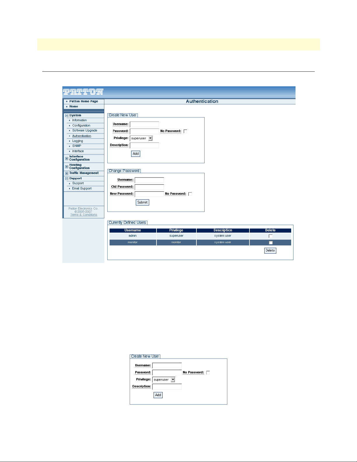
TrinityAE Administrator’s Reference Guide 3 • Authentication
Web Management Interface (WMI)
To access the Authentication main page, click on System > Authentication from the main menu.
Figure 4. Authentication main page
Adding New Users
To add a new user:
1. Type the name of the user into the Username field.
2. If desired, enter a password for the user. If no password is desired, select the No Password checkbox.
3. Select an access group for the user from the Privilege drop-down menu.
4. Enter a description of the user account (optional).
5. Click the Add button.
Figure 5. Add a new user
Web Management Interface (WMI) 27
Page 28
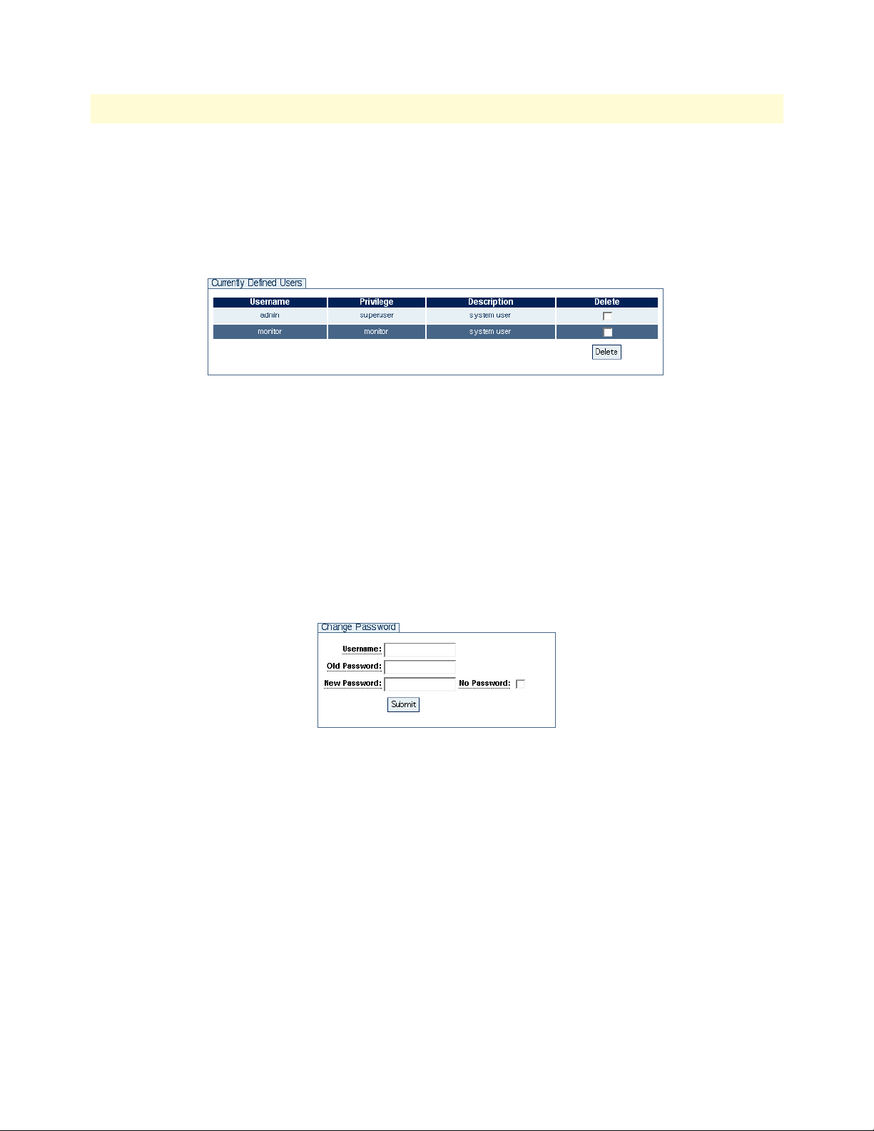
TrinityAE Administrator’s Reference Guide 3 • Authentication
Deleting Users
To delete a user:
1. Select the Delete checkbox of the user from the Currently Defined Users table.
2. Click the Delete button.
Figure 6. Deleting a user
Changing Passwords
To change a password:
1. Enter the username in the Username field.
2. Enter the old password of the user in the Old Password field.
3. Enter the new password in the New Password field, or check No Password.
4. Click Submit.
Figure 7. Change Passwords
Web Management Interface (WMI) 28
Page 29

TrinityAE Administrator’s Reference Guide 3 • Authentication
Command Line Interface (CLI)
The CLI configuration is slightly different from the WMI when configuring authentication features. When
adding a new user from the CLI, the command line does not allow for a "description" field to be entered for
new users. All users are added to the system with the description system user.
The CLI provides an extra option to allow passwords to be submitted in MD5 encrypted form. This feature is
not meant to be used for creating new users, but for administrators exporting/importing previously saved configurations to the system.
Root Mode
Table 9. Authentication Root Mode - CLI Commands
Command Explanation
Trinity# configure Enter the Configuration Mode.
Trinity# show Enter the Show Mode.
Trinity# show users Display currently defined system users.
Command Line Interface (CLI) 29
Page 30

TrinityAE Administrator’s Reference Guide 3 • Authentication
Configuration Mode
Table 10. Authentication Configuration Mode - CLI Commands
Command Explanation
Trinity[config]# username <name>
nopassword privilege <level>
Trinity[config]# username <name>
password <plain-text> privilege <level>
Trinity[config]# username <name>
password <encryption-type>
<encrypted-password> privilege <level>
Trinity[config]# username <name>
changepassword <old password-plaintext> <new password-plain-text>
Trinity[config]# username <name>
changepassword <old password-plaintext> nopassword
Trinity[config]# no username <name> Remove a user with username <name> from the
Add a new user with username <name> and
privilege level <level>.
Available privilege levels are superuser and monitor. No password would be required for login
with this command.
Add a new user with username <name>, password <plain-text>, and privilege level <level>.
Available privilege levels are superuser and monitor. User password is accepted as plain-text,
but will be stored as MD5-hash.
Add a new user with username <name>, an
encrypted password <encrypted-password>,
and privilege level <level>.
Available privilege levels are superuser and monitor. Currently, the only available encryption
type is MD5. The submitted password must be
the MD5-hash form of the plain-text password.
Change the password of the user with username
<name> from <old-plain-text> to <new-plaintext>.
Change the password of the user with username
<name> from <old-plain-text> to empty field.
system.
Command Line Interface (CLI) 30
Page 31

TrinityAE Administrator’s Reference Guide 3 • Authentication
Figure 8. Authentication - CLI
Debugging Information
The Authentication Manager reports the following debugging information:
• All system level failures are reported as LOG_ERR level SYSLOG messages.
• All failures in authentication and authorization –failing to authenticate, validate, renew, or get session keys–
are reported as LOG_WARNING level SYSLOG messages. These are not messages indicating an error in
the operation of the framework but rather warnings for possible attempts to breech system security or
invalid user/component behavior that requires attention.
• All other messages are DEBUG/INFO level messages. They are meant to provide information on the flow
of events through the system.
Command Line Interface (CLI) 31
Page 32

Chapter 4 Logging Management
Chapter contents
Overview ...............................................................................................................................................................32
Web Management Interface (WMI) ......................................................................................................................33
Remote Log Configuration .............................................................................................................................33
Local Log Configuration .................................................................................................................................34
Log Definition Table ................................................................................................................................34
Local Log Viewer ............................................................................................................................................35
Command Line Interface (CLI).............................................................................................................................36
Logging Configuration Commands .................................................................................................................36
32
Page 33

TrinityAE Administrator’s Reference Guide 4 • Logging Management
Overview
This chapter describes logging functions.
Note The menu, commands, and features for your model may vary slightly
from what is shown in this manual. Some models may not include all
of the features mentioned. Refer to the Getting Started Guide for your
device to see which features are available.
To manage logging through the WMI,
see the section “Web Management Interface (WMI)” on page 34.
To manage logging through the CLI,
see the section “Command Line Interface (CLI)” on page 37.
Overview 33
Page 34

TrinityAE Administrator’s Reference Guide 4 • Logging Management
Web Management Interface (WMI)
To access the Logging Management main page, click on System > Logging from the main menu.
Figure 9. Logging Management main page
Remote Log Configuration
To configure the remote log, fill in the following:
• Destination IP: IP address of the remote syslog server (in dotted quad format)
• Protocol: IP protocol that the remote server is listening on (tcp or udp)
• Port: IP port that the remote server is listening on (1-65535)
• Priority: The minimum syslog priority of messages to send (emerg, alert, crit, err, warn, notice, info,
debug)
Click the Add button to save the configuration.
Web Management Interface (WMI) 34
Page 35

TrinityAE Administrator’s Reference Guide 4 • Logging Management
Local Log Configuration
Use the Local Log Definition tab to save syslog messages as a local log file.
Note Only the syslog file is currently supported.
Figure 10. Local Log Definition
To configure the local log, fill in the following:
• Destination File: Name of the log file (Currently limited to syslog)
• Protocol: The file protocol (file)
• Line Count: The minimum number of lines a in a log file before the system rotates it to backup. One
backup log will be kept at all times. (20-200)
• Priority: The minimum syslog priority of messages to save (emerg, alert, crit, err, warn, notice, info,
debug)
Click the Add button to save the configuration.
Log Definition Table
The Log Definition Table shows a list of currently configured logs and is shown on both the Remote and Local
tabs. This table displays both log types simultaneously, and provides a Delete checkbox for each log file.
To delete a log file, select the Delete checkbox for that file, then click the Delete button.
Web Management Interface (WMI) 35
Page 36

TrinityAE Administrator’s Reference Guide 4 • Logging Management
Local Log Viewer
Use the Local Log Viewer tab to view the contents of a local log file. The system will automatically include the
contents of the backup file (up to the total line count specified in the Line Count field).
Note Only the syslog file is currently supported.
Figure 11. Local Log Viewer
Web Management Interface (WMI) 36
Page 37

TrinityAE Administrator’s Reference Guide 4 • Logging Management
Command Line Interface (CLI)
Logging Configuration Commands
Table 11. Logging - CLI Commands
Command Explanation
Trinity[config]# [no] logging remote <ip address>
[port <20-200>] [priority {<0-7>
|emerg|alert|crit|err|warn|notice|info|debug}]
Trinity[config]# [no] logging local {syslog}
[lines <port number>]
[priority {<0-7>
|emerg|alert|crit|err|warn|notice|info|debug}]
[protocol {tcp|udp}]
Trinity# show logging Shows the list of defined local and
Trinity# show logging local {syslog} [lines <2-20>] Shows the contents of a local log file.
Adds a rule which sends syslog messages to a remote syslog file.
Note: Currently this only supports
the persistent files syslog.
Adds a rule that sends syslog messages to a local syslog server.
remote logs.
• Example - Trinity# show logging:
Destination IP/File Protocol
syslog
111.22.33.44
111.55.66.77
• Example - Trinity# show logging local:
Sep 11 19:12:28 kernel: err: VFS: Can\'t find ext3 filesystem on dev sda.
Sep 11 19:13:02 kernel: err: VFS: Can\'t find ext3 filesystem on dev sda.
Sep 11 19:13:08 kernel: err: VFS: Can\'t find ext3 filesystem on dev sda.
Sep 11 19:15:32 kernel: err: sda: assuming drive cache: write through
Sep 11 19:15:32 kernel: err: sda: assuming drive cache: write through
Sep 11 19:35:08 kernel: err: VFS: Can\'t find ext3 filesystem on dev sda.
Sep 11 19:35:57 kernel: err: VFS: Can\'t find ext3 filesystem on dev sda.
Sep 11 19:54:56 kernel: err: VFS: Can\'t find ext3 filesystem on dev sda.
file
tcp
tcp
Port/LnCnt
20
514
514
Priority
err
err
emerg
Command Line Interface (CLI) 37
Page 38

Chapter 5 SNMP Configuration
Chapter contents
Overview ...............................................................................................................................................................39
Configuration Overview .................................................................................................................................39
Web Management Interface (WMI) ......................................................................................................................40
Configuring the Server ....................................................................................................................................41
Managing SNMP Communities (SNMPv1 and SNMPv2) .............................................................................41
Adding SNMP Communities ....................................................................................................................41
Deleting SNMP Communities ..................................................................................................................41
Managing SNMP Users (SNMPv3) ................................................................................................................42
Adding SNMP Users .................................................................................................................................42
Deleting SNMP Users ...............................................................................................................................42
Managing System Variables .............................................................................................................................42
Command Line Interface (CLI).............................................................................................................................43
SNMP commands ..........................................................................................................................................43
38
Page 39

TrinityAE Administrator’s Reference Guide 5 • SNMP Configuration
Overview
This chapter describes how to configure Simple Network Management Protocol (SNMP) on the Trinity platform. SNMP allows for the exchange of management information between network devices.
Trinity supports the following SNMP MIBs:
– Standard MIB 2
– RFC 1406 - DS1 (T1/E1)
Note The menu, commands, and features for your model may vary slightly
from what is shown in this manual. Some models may not include all
of the features mentioned. Refer to the Getting Started Guide for your
device to see which features are available.
Configuration Overview
To monitor the device using SNMP:
1. Add the SNMPv1/2c communities and/or SNMPv3 users that may access the device.
2. Set the system variables: sysDescription, sysLocation, etc. (optional).
3. Enable the agent.
SNMPv1/2c communities may optionally be limited to certain IP addresses. By default, the IP address and
netmask are set to 0.0.0.0, and requests from the community will be accepted regardless from where they originate. However, if the IP address and netmask are set, the request must originate from the designated address.
Once the steps above have been performed, an SNMP management entity may begin to monitor the device.
To configure SNMP through the WMI,
see the section “Web Management Interface (WMI)” on page 40.
To configure SNMP through the CLI,
see the section “To update system vartiables, enter information for the following fields:” on page 42.
Overview 39
Page 40

TrinityAE Administrator’s Reference Guide 5 • SNMP Configuration
Web Management Interface (WMI)
To access the SNMP main page, click on System > SNMP from the main menu.
Figure 12. SNMP main page
Web Management Interface (WMI) 40
Page 41

TrinityAE Administrator’s Reference Guide 5 • SNMP Configuration
Configuring the Server
To enable/disable the server:
1. In the Server Configuration section, select Enabled or Disabled from the State drop-down menu.
2. Click Update.
Managing SNMP Communities (SNMPv1 and SNMPv2)
Figure 13. SNMP Communities
Adding SNMP Communities
To add an SNMP community:
1. In the Communities section, enter a unique name in the Community String text box.
2. Read-only is the only available Access option.
3. Enter an IP address (in standard dotted quad format) in the Source IP field.
4. Enter a netmask address (in /xx format) in the Source Netmask field.
5. Click Add.
Deleting SNMP Communities
To delete an SNMP community:
1. Select the Delete checkbox for the community in the Communities table.
2. Click Delete.
Web Management Interface (WMI) 41
Page 42

TrinityAE Administrator’s Reference Guide 5 • SNMP Configuration
Managing SNMP Users (SNMPv3)
Figure 14. SNMP Users
Adding SNMP Users
To add an SNMP user:
1. In the Users section, enter a unique name in the Username text box.
2. Enter a unique password in the Password text box. The password must be at least 8 characters.
3. Read-only is the only available Access option.
4. Click Add.
Deleting SNMP Users
To delete an SNMP user:
1. Select the Delete checkbox for the user in the Users table.
2. Click Delete.
Managing System Variables
Figure 15. System Variables
To update system vartiables, enter information for the following fields:
• sysDescription – A description of the system
• sysLocation – The location of the system
• sysContact – The email address of the administrator for the system
• sysName – The name of the system
• sysServices – SNMP services for the system
• sysObjectId – The object ID for the system
Click Update to save the changes.
Web Management Interface (WMI) 42
Page 43

TrinityAE Administrator’s Reference Guide 5 • SNMP Configuration
Command Line Interface (CLI)
The following commands are used to configure SNMP:
SNMP commands
Table 12. SNMP - CLI Commands
Command Explanation
Trinity# configure snmp Enter the SNMP configuration mode.
Trinity[snmp]# [no] shutdown Start/stop the SNMP agent.
Trinity[snmp]# [no] community <commu-
nity-string> read-only [source <ip> <netmask>]
Trinity[snmp]# [no] user <username>
password <password> read-only
Trinity[snmp]# sysdescription <string> Enter a description of the system.
Trinity[snmp]# syslocation <string> Enter the location of the system.
Trinity[snmp]# syscontact <string> Enter the email address of the system administrator.
Trinity[snmp]# sysname <string> Enter the name of the system.
Trinity[snmp]# sysservices <0-127> Enter an integer for system services.
Trinity[snmp]# sysobjectid <oid> Set a unique object identifier for the system.
Trinity[snmp]# show Enters show mode for SNMP.
Trinity# show snmp Show the SNMP configuration.
Add/remove an SNMPv1/2c community.
Add/remove an SNMPv3 user.
(The integer correlates with layer functionality, i.e. physical, datalink, internet, application, ect...).
The following is an example of the show snmp command:
agent is enabled
community access source
---------------- ---------- ------------------
public read-only 0.0.0.0/0
limited read-only 192.168.200.1/32
username access
---------------- ----------
user1 read-only
sysDescription: My Description
sysLocation: My Location
sysContact: my@contact.com
sysName: My Name
sysServices: 6
sysObjectId: <unset>
Command Line Interface (CLI) 43
Page 44

Chapter 6 Interface Status
Chapter contents
Overview ...............................................................................................................................................................45
Web Management Interface (WMI) ......................................................................................................................46
Viewing Errors ................................................................................................................................................46
Editing Interfaces ............................................................................................................................................46
Command Line Interface (CLI).............................................................................................................................47
Root Mode .....................................................................................................................................................47
Configuration Mode .......................................................................................................................................48
44
Page 45

TrinityAE Administrator’s Reference Guide 6 • Interface Status
Overview
This chapter describes the interface configuration options for Ethernet interfaces, bridge groups, and VLANs.
Note The menu, commands, and features for your model may vary slightly
from what is shown in this manual. Some models may not include all
of the features mentioned. Refer to the Getting Started Guide for your
device to see which features are available.
The interface properties that can be configured are:
• Enable: Enable or disable administration of an interface.
• ARP: Enable or disable transmission and reception of ARP packets.
• Multicast: Enable or disable transmission and reception of multicast packets.
• MTU: Set the size of the maximum transmission unit (MTU).
• Speed/Duplex (Ethernet interfaces only): Set the Ethernet speed to 10 Mbps, 100 Mbps, or auto. Set
duplex to half, full, or auto.
To configure interfaces through the WMI,
see the section “Web Management Interface (WMI)” on page 46.
To configure interfaces through the CLI,
see the section “Command Line Interface (CLI)” on page 47.
Overview 45
Page 46

TrinityAE Administrator’s Reference Guide 6 • Interface Status
Web Management Interface (WMI)
To access the Interface Status main page, click on System > Interface from the main menu on the left of the
screen.
Figure 16. Interface Status main page
Viewing Errors
To view detailed errors in the status table, click the Expand Errors button.
To hide error details, click the Collapse Errors button.
Editing Interfaces
To update configuration details of interfaces from the status table, click on the hyperlink of the interface in the
Interface column. The link will display cofiguration details for the specific interface. Click Update to save
changes.
Figure 17. Editing an Ethernet interface from the status page
Note The Speed/Duplex option is only available for Ethernet interfaces.
Web Management Interface (WMI) 46
Page 47

TrinityAE Administrator’s Reference Guide 6 • Interface Status
Command Line Interface (CLI)
Root Mode
Table 13. Interface Root Mode - CLI Commands
Command Explanation
Trinity# configure interface <interface-type>
<interface-name>
Trinity# show interface <interface-type> <interface-name>
The following is example output of the show interface command (The ethernet interface eth0 is used in this
example):
eth0 is up, line protocol is up
Hardware is static, address is 00:a0:ba:00:9d:ea
Speed is administratively auto, operationally 100full
Internet address 192.168.200.98/24 192.168.200.255
Internet address 192.168.200.10/24 192.168.200.255secondary
MTU 1524
ARP enabled
Multicast enabled
Rx Statistics
0 bytes in 0 packets
0 errors 0 drops, 0 overruns
0 multicast packets
Tx Statistics
398 bytes in 5 packets
0 errors 0 drops, 0 collisions 0 carrier errors
Enter the interface configuration mode for
<interface-name>.
Show the current configuration and status of
<interface-name>.
Command Line Interface (CLI) 47
Page 48

TrinityAE Administrator’s Reference Guide 6 • Interface Status
Configuration Mode
Table 14. Interface Configuration Mode - CLI Commands
Command Explanation
Trinity# [no] shutdown Administratively disable this interface. A physical link may still be estab-
lished, but no packets will be transmitted and any packets received will be
ignored.
The no shutdown command administratively enables this interface.
Trinity# [no] mtu <mtu> Set the maximum transmission unit (MTU) for this interface.
The no mtu <mtu> command returns the MTU back to its default value
(1524 for Ethernet interfaces).
Trinity# [no] enable arp Allow this interface to transmit ARP requests and respond with ARP replies.
The no enable arp command causes the interface to not transmit ARP
requests and to ignore any received ARP requests.
Trinity# [no] enable multicast
Trinity# show Show the current configuration and status of the interface.
Allow this interface to transmit and receive multicast datagrams.
The no enable multicast command causes the interface to not transmit
multicast datagrams and to ignore any that are received.
This command performs the same function as show interface <inter-
face-type> <interface-name> available in the root mode.
Command Line Interface (CLI) 48
Page 49

Chapter 7 IP Address Configuration
Chapter contents
Overview ...............................................................................................................................................................50
Configuration Overview .................................................................................................................................50
Terms used with IP Interfaces ...................................................................................................................50
Web Management Interface (WMI) ......................................................................................................................52
Adding an IP Interface ....................................................................................................................................53
IP Configuration .............................................................................................................................................53
Adding a DHCP Client ..................................................................................................................................54
DHCP Configuration .....................................................................................................................................54
Command Line Interface (CLI).............................................................................................................................55
IP Interface Commands ..................................................................................................................................55
DHCP Client Commands ..............................................................................................................................55
49
Page 50

TrinityAE Administrator’s Reference Guide 7 • IP Address Configuration
Overview
This chapter describes how to add or remove IP addresses from Ethernet-like interfaces.
Note The menu, commands, and features for your model may vary slightly
from what is shown in this manual. Some models may not include all
of the features mentioned. Refer to the Getting Started Guide for your
device to see which features are available.
Configuration Overview
The user can add or remove IP addresses to and from Ethernet interfaces from both the CLI and the WMI.
The following parameters are configurable when adding an IP address to an Ethernet interface:
• IP address: Standard dotted quad. format (Required)
• Network mask: Standard dotted quad format or slash notation (Defaults to /32)
• Broadcast in the following ways:
"+": auto calculates the high-bit broadcast (Default)
"-": auto calculates the low-bit broadcast
- Dotted quad (dotted quad format) – (Note: The broadcast will not be verified to be correct when using
the dotted quad format).
The following information is available when adding DHCP addresses:
• Accept Routes forces routes supplied to by the DHCP server to be added to the routing table
• Accept DNS forces DNS server supplied by the DHCP server to be added to the DNS pool
• Accept Hostname forces the hostname supplied by the DHCP server to be applied
For DHCP addresses, the user is also able to:
• Release
• Renew
Terms used with IP Interfaces
• Dotted quad (standard dotted quad format): 32-bit IP address split into 4 8-bit integers (0-255) separated
by a '.'. (i.e., 0.0.0.0 to 255.255.255.255)
• Ethernet-like: Interfaces capable of sending L2 ethernet style headers (i.e., Physical ethernet, VLANs,
Bridge Groups, BCP)
• High-bit broadcast: Broadcast address calculated by replacing the masked out bits with 1 (i.e.,
192.168.252.100/24 -> 192.168.252.255)
• Low-bit broadcast: Broadcast address calculated by replacing masked out bits with 0 (i.e.,
192.168.252.100/24 -> 192.168.252.0)
• Net-block: A set of IP addresses logically grouped by a network mask.
Overview 50
Page 51

TrinityAE Administrator’s Reference Guide 7 • IP Address Configuration
• Secondary IP address: For any given net-block, there can be only one primary IP address. That primary IP
is used as a source address for communication initiated by the device. Any additional IP addresses within
the same net-block are considered as secondary addresses and are internally linked to the primary IP address
in that net-block. A Trinity device will respond to secondary IP addresses. If a primary IP is removed, then
all secondaries linked to it are removed as well.
• Slash notation: A special network mask notation allowing a user to specify only the masked bits. (i.e., /0
through /32)
To configure IP interfaces through the WMI,
see the section “Web Management Interface (WMI)” on page 52.
To configure IP interfaces through the CLI,
see the section “Command Line Interface (CLI)” on page 55.
Overview 51
Page 52

TrinityAE Administrator’s Reference Guide 7 • IP Address Configuration
Web Management Interface (WMI)
To access the IP Interface Management main page, click on Interface Configuration > IP Interface from the
main menu on the left of the screen.
Figure 18. IP Address Configuration main page
Web Management Interface (WMI) 52
Page 53

TrinityAE Administrator’s Reference Guide 7 • IP Address Configuration
Adding an IP Interface
To add an IP interface:
1. Choose a valid interface from the Interface drop-down menu.
2. Enter the IP address, Netmask, and Broadcast address.
3. Click the Add button to save the IP interface.
Figure 19. Adding an IP interface
IP Configuration
The IP Configuration table shows the current IP configuration for the device:
• Interface: Interface that is configured for the IP address
• IP: IP address in dotted quad format
• Netmask: Network mask in dotted quad format
• Broadcast: Broadcast address
• Flags:
- Secondary: Indicates an IP address as secondary
- DHCP: Indicates an IP was DHCP-assigned and cannot be removed
• Delete: Select the checkbox of the interface to delete, then click the Delete button.
Figure 20. IP Configuration
Web Management Interface (WMI) 53
Page 54

TrinityAE Administrator’s Reference Guide 7 • IP Address Configuration
Adding a DHCP Client
To add a DHCP client:
1. Choose a valid interface from the Interface drop-down menu.
2. Select to accept routes, accept DNS, and/or accept hostname (these are optional features).
3. Click Add.
Figure 21. Adding a DHCP client
DHCP Configuration
The DHCP Configuration table shows the current DHCP configurations for the device:
• Interface: Interface that has DHCP enabled
• Accepting Routes: Indicates that routes given by the DHCP server are added to the routing table
• Accepting DNS: Indicates that DNS servers returned by the DHCP server are accepted
• Accepting Hostname: Indicates that the hostname supplied by the DHCP server is accepted
• Disable: To disable a DHCP configuration, click the Disable button in the row of the interface.
Note A DHCP lease cannot be released or renewed through the WMI.
See “DHCP Client Commands” on page 55.
Figure 22. DHCP configuration
Web Management Interface (WMI) 54
Page 55

TrinityAE Administrator’s Reference Guide 7 • IP Address Configuration
Command Line Interface (CLI)
IP Interface Commands
All IP interface commands are accessed by entering configure interface <interface type> <interface name>.
Table 15. IP Interface - CLI Commands
Command Explanation
Trinity# no ip address <IP> Removes the specified IP.
Trinity# ip address <IP> [netmask <mask>
[broadcast <broadcast>]]
DHCP Client Commands
All commands are accessed by entering configure interface <interface type> <interface name>. Only the subset of commands that deal with DHCP client configuration are shown in table 16.
Table 16. DHCP client - CLI Commands
Command Explanation
Trinity# ip address dhcp [release|renew|request
<ip> [ignore <ign options>]|ignore <ign options>]
[ignore route]
[ignore hostname]
[ignore dns]
Trinity# no ip address dhcp Disable DHCP client on this interface.
Adds a new IP address with the configured options.
• release - release the current DHCP lease on an
interface, and will fail if DHCP is not enabled
• renew - renews the current DHCP lease on an
interface, and will fail if DHCP is not enabled
• request - requests an initial IP address from the
DHCP (it is only a request and the server might
refuse and assign a different IP address)
• ignore - specifies the DHCP options that will be
ignored (options explained below)
Ignored items can be specified in any order but
can only exist on the line once.
• route - ignore any supplied default route from
the server on this interface
• hostname - ignore any supplied hostname
from the server on this interface
• dns - ignore any supplied DNS servers from the
server on this interface
Command Line Interface (CLI) 55
Page 56

Chapter 8 VLAN Configuration
Chapter contents
Overview ...............................................................................................................................................................57
Configuration Overview .................................................................................................................................57
Web Management Interface (WMI) ......................................................................................................................58
Create VLAN ..................................................................................................................................................58
Manage VLAN Interfaces ................................................................................................................................58
Command Line Interface (CLI).............................................................................................................................59
VLAN Configuration Commands ...................................................................................................................59
VLAN Configuration Example .................................................................................................................59
Show VLAN Information ...............................................................................................................................60
56
Page 57

TrinityAE Administrator’s Reference Guide 8 • VLAN Configuration
Overview
This chapter describes how to configure VLANs on the Trinity platform.
Note The menu, commands, and features for your model may vary slightly
from what is shown in this manual. Some models may not include all
of the features mentioned. Refer to the Getting Started Guide for your
device to see which features are available.
Configuration Overview
The bulk of the configuration of a VLAN works exactly like a regular Ethernet interface. For those operations,
e.g. setting an IP address, see Chapter 7, “IP Address Configuration” on page 49.
This chapter explains how to create and delete VLANs on a physical interface.
To configure VLANs through the WMI,
see the section “Web Management Interface (WMI)” on page 58.
To configure VLANs through the CLI,
see the section “Command Line Interface (CLI)” on page 59.
Overview 57
Page 58

TrinityAE Administrator’s Reference Guide 8 • VLAN Configuration
Web Management Interface (WMI)
To access the VLAN Configuration main page, click on Interface Configuration > VLAN from the main
menu on the left of the screen.
Figure 23. VLAN Configuration main page
Create VLAN
To create a new VLAN:
1. Choose an Interface from the drop-down menu. Note that interfaces that have been shutdown cannot
have a VLAN created on them. If an interface is not listed, make sure that it has not been shutdown.
2. Type the VLAN ID (VID) (a number between 1 and 4094) into the text field.
3. Click Create. The VLAN configuration details will be displayed.
Figure 24. Create VLAN
Manage VLAN Interfaces
The VLAN Interfaces table lists the existing VLANs.
To view a VLAN’s details, click on the name of the VLAN device.
To delete a VLAN interface, select the Delete checkbox for that profile, then click the Delete button.
Figure 25. VLAN Interfaces
Web Management Interface (WMI) 58
Page 59

TrinityAE Administrator’s Reference Guide 8 • VLAN Configuration
Command Line Interface (CLI)
VLAN Configuration Commands
Table 17. VLAN - CLI Commands
Command Explanation
Trinity# [no] interface vlan <interface> <vlan-id>
VLAN Configuration Example
VLANs are created on interfaces as shown in the following example:
Trinity# configure
Trinity[config]# interface vlan eth0 23
Trinity[vlan(eth0.0023)]#
Interface specific properties of A VLAN can be configured with standard interface configuration commands, as
documented for ethernet interfaces.
<interface> specifies the interface to create the VLAN on.
The <vlan-id> is an integer between 1 and 4094.
The no interface command deletes the specified VLAN from
the interface, if it exists.
Command Line Interface (CLI) 59
Page 60

TrinityAE Administrator’s Reference Guide 8 • VLAN Configuration
Show VLAN Information
The show command is used to display information about VLANs. It can be used from the root mode, configure mode, or configure mode of a specific VLAN.
Table 18. Show VLAN Information - CLI Commands
Command Explanation
Trinity# show interface vlan Displays all VLAN information.
Trinity[config]# show interface vlan Displays all VLAN information.
Trinity# show interface vlan eth0 Displays VLANs on eth0
Trinity# show interface vlan eth0 23 Displays VLAN eth0.0023
Trinity[vlan-eth0.0023# show Displays VLAN eth0.0023
Trinity# show interface vlan [ interface [
vlan-id ] ]
The show interface vlan mode displays one of the
following options at a time:
• Interface: If a regular interface is given, only VLANs
on that interface will be listed.
• Vlan-ID: If a Vlan-ID is given, only VLANs using that
Vlan-ID will be listed.
• Vlan-interface: If a VLAN interface is given (the
interface followed by a dot followed by the zero-padded Vlan-ID, for example, eth00.0023), only that
VLAN will be listed.
Displays VLANs on a specific interface.
Displays VLAN information for a specific VLAN ID.
From configure mode for a specific VLAN, the show command displays information for that interface only.
The information displayed is a combination of the standard information for an ethernet interface, combined
with some VLAN specific information.
For example:
eth0.0023 is up , line protocol is up
Hardware is static, address is
Speed is Auto
Internet address 10.1.1.1/24 10.1.1.255
MTU 2128606600
ARP enabled
Multicast enabled
Rx Statistics
0 bytes in 0 packets
0 errors, 0 drops, 0 overruns
0 multicast packets
Tx Statistics
0 bytes in 0 packets
0 errors, 0 drops, 0 collisions, 0 carrier errors
VLAN:
Command Line Interface (CLI) 60
Page 61

TrinityAE Administrator’s Reference Guide 8 • VLAN Configuration
VID: 23
Interface: eth0
Reorder Headers: On
Traffic Statistics:
Total Headroom Inc: 0
Total Encap On Xmit: 0
Command Line Interface (CLI) 61
Page 62

Chapter 9 Bridge Group Configuration
Chapter contents
Overview ...............................................................................................................................................................63
Configuration Overview .................................................................................................................................63
Web Management Interface (WMI) ......................................................................................................................65
Bridge Group Configuration ...........................................................................................................................66
Add/Configure Bridge Groups ..................................................................................................................66
Delete Bridge Groups ................................................................................................................................66
Manage Interfaces .....................................................................................................................................66
STP Configuration .........................................................................................................................................67
Set STP Parameters ...................................................................................................................................67
Set STP Forwarding ..................................................................................................................................67
Show STP Status Information ...................................................................................................................67
Manage MAC Addresses .................................................................................................................................68
Display MAC Address Information ...........................................................................................................68
Add MAC Filter Rules ..............................................................................................................................68
Display/Delete MAC Filter Rules ..............................................................................................................68
Command Line Interface (CLI).............................................................................................................................69
Bridge Group Commands ...............................................................................................................................69
62
Page 63

TrinityAE Administrator’s Reference Guide 9 • Bridge Group Configuration
Overview
This chapter describes how to configure bridge groups and manage bridge group interfaces.
Note The menu, commands, and features for your model may vary slightly
from what is shown in this manual. Some models may not include all
of the features mentioned. Refer to the Getting Started Guide for your
device to see which features are available.
Configuration Overview
The bridge group configuration on the system can be divided into six groups:
1. Managing a bridge group:
– Adding and deleting a bridge group
– Setting the ageing time value (in seconds, default 300) for the bridge group:
Ageing time is the number in seconds a MAC address will be kept in the forwarding database of the
bridge group after having received a packet from this address.
– Enabling and disabling Spanning Tree Protocol (STP) for the bridge group. STP manages links in the
bridge group and prevents loops from occurring in a network.
2. Managing interfaces:
– Attaching and removing an interface to/from a bridge group
– Setting the path cost for an interface:
(The cost of sending/receiving a packet from this interface; also referred to as the port priority).
The faster interfaces should have lower path costs. These values are used in the computation of the minimal spanning tree.
3. Configuring STP:
– Setting the priority of the bridge group (integer between 0-65525, default=32768):
The bridge with the lowest priority is selected as the root bridge in the spanning tree.
– Setting the forwarding delay (in seconds, default=15):
Forwarding delay is the number in seconds spent in each of the listening and learning states, before the
forwarding state is entered.
– Setting the hello interval (in seconds, default=2):
The hello interval is the time a hello packet is sent out of the root bridge. Hello packets are used to com-
municate topology information throughout the entire bridged local area network.
– Setting the maximum message age (in seconds, default=20):
If the last seen hello packet is older than this number of seconds, the bridge in question will start the
procedure to take over as the root bridge in the spanning tree.
– Forward/Drop STP packets on a per interfaces basis:
Configures which interfaces of the bridge group will participate in dissemination of spanning tree information (default all interfaces forward STP packets).
Overview 63
Page 64

TrinityAE Administrator’s Reference Guide 9 • Bridge Group Configuration
4. Configuring the bridge group interface:
– Enable and disable the bridge group interface
– Set MTU size (in bytes)
– Add an IP address to the bridge group interface
– Toggle ARP and MULTICAST flags
5. Monitoring status:
– Displaying current forwarding database
– Displaying current STP configuration
– Displaying bridge group interface configuration
– Displaying existing bridge groups, interfaces enslaved in them, and STP status
6. MAC address filtering:
– Permit and deny packets based on the source MAC address, packet destination MAC address, interface,
egress or ingress direction
All six configuration groups can be accessed via the command line interface (CLI). However, the bridge group
configuration page of the Web Management Interface (WMI) allows access to bridge-group-only configuration. Therefore, IP and other ethernet-like configuration (enable/disable, MTU, etc.) is only possible through
IP and Ethernet WMI pages.
To configure the Bridge Group Mangement component through the WMI,
see the section “Web Management Interface (WMI)” on page 65.
To configure the Bridge Group Mangement component through the CLI,
see the section “Command Line Interface (CLI)” on page 69.
Overview 64
Page 65

TrinityAE Administrator’s Reference Guide 9 • Bridge Group Configuration
Web Management Interface (WMI)
To access the Bridge Group Configuration main page, click on Interface Configuration > Bridge Group from
the main menu on the left of the screen.
Figure 26. Bridge Group Configuration main page
The Bridge Group Configuration page consists of three tabs:
• “Bridge Group Configuration” on page 66
• “STP Configuration” on page 67
• “Manage MAC Addresses” on page 68
Web Management Interface (WMI) 65
Page 66

TrinityAE Administrator’s Reference Guide 9 • Bridge Group Configuration
Bridge Group Configuration
Add/Configure Bridge Groups
To add a bridge group:
1. Enter the name of the bridge group in br<number> format, then
click Add.
To configure a bridge group:
1. Select the group from the Bridge Group drop-down menu.
2. Enter the Ageing Value in seconds, and select enable or disable
from the STP Status drop-down menu.
3. Click Submit.
Delete Bridge Groups
To delete a bridge group:
1. Select the Delete checkbox for the bridge group in the Bridge Groups table, then click Delete.
Manage Interfaces
Interfaces can be attached and configured using the Manage Interfaces table:
• Attached To: To attach an interface to a bridge group, select a bridge group from the Attached To drop-
down menu. If the interface is not attached to any bridge groups, the keyword None is displayed.
• Cost (optional): If the interface is not attached to any bridge group, the user may enter a cost value in the
Cost field. If the interface is already attached to a bridge group, the Cost field displays either the value set by
the user or keyword "default" if no cost value was specified.
• STP (read only): The STP column displays whether the attached interface is sending STP information
(default = forward).
• Force (optional): Select the Force checkbox to remove IP address information from the interface beforeat-
taching it to the bridge group. It is usually recommended to to remove any IP addresses from attached interfaces in order for the bridge group to operate correctly.
Figure 27. Managing interfaces
To attach an interface to a bridge group, select the bridge group from the drop-down menu and click Submit.
To remove an interface from a bridge group, select None from the Attached To drop-down menu and click
Submit.
Web Management Interface (WMI) 66
Page 67

TrinityAE Administrator’s Reference Guide 9 • Bridge Group Configuration
STP Configuration
Set STP Parameters
Enter information for the following fields in the Set STP Parameters section to configure STP:
1. Select a bridge group from the Bridge Group drop-down menu.
2. Enter a number in the range (0-65535) in the Bridge Priority field.
3. Enter seconds in the range (0-65353) in the Forwarding Delay field.
4. Enter seconds in the range (0-65353) in the Hello Interval field.
5. Enter seconds in the range (0-65353) in the Maximum Age field.
6. Click Submit.
Figure 28. STP Configuration
Set STP Forwarding
STP Forwarding prevents loops in a network by allowing a bridge group to forward traffic on a designated
interface. To set up STP forwarding for a bridge group:
1. In the Set STP Forwarding section, select a bridge group from the Bridge Group drop-down menu.
2. Select an interface from the Interface drop-down menu.
3. Select forward from the Action drop-down menu.
4. Click Submit.
(To turn off STP forwarding, select drop from the Action drop-down menu).
Show STP Status Information
To show the full STP status for a bridge group:
1. In the Show Status Information section, select a bridge group from the Bridge Group drop-down menu.
2. Click Submit.
Web Management Interface (WMI) 67
Page 68

TrinityAE Administrator’s Reference Guide 9 • Bridge Group Configuration
Manage MAC Addresses
Display MAC Address Information
The MAC Address Information table displays the contents of the bridge group forwarding database for the
selected bridge group. The rows display the name of the local port where this MAC address is observed, the
MAC address, whether it is local, and the remaining time in seconds until this entry ages out and is removed
from the table. Local entries have 0.0 seconds for their ageing value but are never removed from the table.
Figure 29. Displaying MAC address information
Add MAC Filter Rules
Use the Filter Configuration table to add MAC filter rules for a selected bridge group. Five MAC addresses can
be submitted at a time. The following settings may be configured:
• Port: Select egress to apply the new filter rule to outgoing packets, or select ingress to apply the rule to
incoming packets.
• Source MAC address: Enter a source MAC address that the filter rule will try to match, or leave this field as
00:00:00:00:00:00 to match all source MAC addresses.
• Destination MAC address: Enter a destination MAC address that the filter rule will try to match, or leave
this field as 00:00:00:00:00:00 to match all destination MAC addresses.
• Interface: Select an interface for the filter rule.
• Filter: Select permit or deny for packets matching the filter rule criteria.
Figure 30. Configuring MAC filter rules
Display/Delete MAC Filter Rules
Use the Filter Display table to show the existing MAC filter rules for a selected bridge group. Entries can be
deleted by selecting the corresponding Delete checkbox and clicking the Submit button.
Web Management Interface (WMI) 68
Page 69

TrinityAE Administrator’s Reference Guide 9 • Bridge Group Configuration
Command Line Interface (CLI)
Bridge Group Commands
Table 19. Bridge Group Configuration - CLI Commands
Command Explanation
Trinity# configure [no] interface bridge {<id> | br<id>} Enter bridge configura-
Trinity[bridge(br0)]#
Trinity[bridge(br0)]# [no] attach <dev> [pathcost <value>] [force] Manage interfaces
Trinity[bridge(br0)]# ageing <value> Set ageing value
Trinity[bridge(br0)]# [no] enable {arp | multicast | stp } Enable/disable STP
Trinity[bridge(br0)]# stp {bridgeprio | hello | maxage | fwdelay}
<value>
Trinity[bridge(br0)]# [no] filter mac {ingress | egress} {permit | deny}
[source <srcmac>] [destination <dstmac>] [interface <dev>]
Trinity[bridge(br0)]# filter stp <dev> Configure filter rules for
Trinity[bridge(br0)]# mtu <value> Set MTU value
Trinity[bridge(br0)]# [no] ip {.....} Add an IP address to
Trinity[bridge(br0)]# show {macs | stp | filter} Display details
Trinity[bridge(br0)]# [no] shutdown Disable the bridge
tion mode
Configure STP settings
Configure filter rules for
MAC addresses
STP packets
the bridge interface
group
Detailed explanations for table 19:
• Bridge: The bridge command under the interface mode moves the CLI into the bridge group context, cre-
ating a new bridge group if the given bridge group id does not exist in the system. The <id> is a unique positive integer number representing the bridge group. The CLI accepts both <id> and br<id> as valid input.
The no bridge command removes the bridge group from the system.
• Ageing: Under the bridge group context, the ageing command sets the value of the ageing time, where
<value> is in seconds.
• Enable: The enable command enables spanning tree protocol (STP), and also the ARP or Multicast support
on the bridge group interface. Entering [no] in front of the command disables STP, ARP or Multicast support on the interface.
• STP: The stp command sets the values of STP parameters, where <value> is a positive integer for the
bridgeprio parameter, and is in seconds for the hello, maxage, and fwdelay parameters.
• MTU: The mtu command sets the maximum transmission unit size for the packets transmitted through
the bridged interfaces, where <value> is in bytes.
• IP: The ip command adds an IP address to the bridge group interface. When a bridge group has an IP
address, it can act as a routeable network node. Therefore, it becomes possible to send/recieve packets (e.g.
ping) to the bridge group. The no ip command removes the IP address from the bridge group.
Command Line Interface (CLI) 69
Page 70

TrinityAE Administrator’s Reference Guide 9 • Bridge Group Configuration
• Filter: The filter command has two options, mac and stp:
- The filter mac command adds a new MAC address-based filter rule to either permit or deny packets based
on the direction (ingress (incoming) or egress (outgoing)), source MAC address specified in <srcmac>, destination MAC address specificed in <dstmac>, and the interface name <dev>. The no filter mac command
removes the MAC address filter rule from the bridge group.
- The filter stp comand adds a filter to stop forwarding of STP information on the interface <dev>. The no
filter stp command enables forwarding of STP information on the interface.
• Shutdown: The shutdown command disables the bridge group. The bridge group configuration is retained,
but no traffic can be forwarded through the bridged interfaces when disabled. The no shutdown command
enables the bridge group.
• Show: The show command under the bridge group context ccan display MAC address forwarding database,
the STP status, and the MAC address based filter rules. (See figure 31 on page 70 through figure 33).
Figure 31. Show MAC address forwarding database
Figure 32. Show STP configuration
Command Line Interface (CLI) 70
Page 71

TrinityAE Administrator’s Reference Guide 9 • Bridge Group Configuration
Figure 33. Configure and show MAC filter information
The show command under the configure mode can additionally display "ethernet-like" and IP configuration
information on the bridge group:
Figure 34. Show interface configuration
Command Line Interface (CLI) 71
Page 72

Chapter 10 T1/E1 Configuration
Chapter contents
Overview ...............................................................................................................................................................73
Configuration Overview .................................................................................................................................73
Web Management Interface (WMI) ......................................................................................................................74
Configure Clocking ........................................................................................................................................74
Manage Ports ..................................................................................................................................................74
Port Configuration ....................................................................................................................................75
Mode. ................................................................................................................................................. 75
Configuration Settings ........................................................................................................................ 75
HDLC Channels................................................................................................................................. 76
Port Status ................................................................................................................................................76
Port History ..............................................................................................................................................76
Command Line Interface (CLI).............................................................................................................................77
Configuring the Clock Source .........................................................................................................................77
Selecting T1 or E1 Mode ................................................................................................................................77
Configuring T1 or E1 Applications .................................................................................................................77
Creating HDLC Channels ..............................................................................................................................78
Showing Configuration and Status ..................................................................................................................79
Clearing Errors and Performance History .......................................................................................................80
Using Test Modes ...........................................................................................................................................80
72
Page 73

TrinityAE Administrator’s Reference Guide 10 • T1/E1 Configuration
Overview
This chapter describes how to configure T1/E1 on the Trinity platform.
Note The menu, commands, and features for your model may vary slightly
from what is shown in this manual. Some models may not include all
of the features mentioned. Refer to the Getting Started Guide for your
device to see which features are available.
Configuration Overview
T1 and E1 ports are used for framing and signaling data. T1 is used primarily in the USA, and it consists of 1
framing timeslot and 23 timeslots that can carry data. E1 is used in most other countries, and it consists of 1
timeslot used for frame syncronization and 31 timeslots that can carry data. In some models, the T1/E1
timeslots are mapped to HDLC channels that can then be used to transport PPP packets.
Configuring HDLC channels over the T1/E1 ports is done using the following steps:
• Select the mode - either T1 or E1
• Configure the framing, line code, line build out, application, and LOS threshold
• Map timeslots to HDLC channels
To configure T1/E1 through the WMI,
see the section “Web Management Interface (WMI)” on page 74.
To configure T1/E1 through the CLI,
see the section “Command Line Interface (CLI)” on page 77.
Overview 73
Page 74

TrinityAE Administrator’s Reference Guide 10 • T1/E1 Configuration
Web Management Interface (WMI)
To reach the main T1/E1 Configuration page, click on Interface Configuration > T1/E1 in the main menu.
Figure 35. T1/E1 Configuration screen
Configure Clocking
To configure the clock source:
1. Choose an option from the Primary Clock drop-down menu.
– Internal: Use the internal clock as the clock source.
– Primary/Secondary: Use the clock recovered from the primary port, the clock recovered from the sec-
ondary port, or the internal clock. When to use which clock source depends on the fallback mode and
the link state of the primary and secondary ports.
2. Select an option from the Fallback Mode drop-down menu.
– None: Use the primary clock source while the port is up. Otherwise, use the internal clock.
– Fallback: Use the primary clock source until the port goes down. Then, use the secondary clock while
the port is up, and the internal clock otherwise. To use the primary clock source again, the fallback condition must be manually reset.
– Fall-Forward: Use the primary clock source while the port is up. Use the secondary clock source while
the primary port is down. Use the internal clock while both the primary and secondary ports are down.
Note The clock will fall-forward to the primary clock source when the pri-
mary clock source comes back up.
3. Click Update.
Manage Ports
To view the configuration screen for a T1/E1 port:
1. Click on the link of the port that you would like to configure in the Port column.
2. The link will lead to the port’s status screen. On the port status screen, click on the Configuration tab.
Web Management Interface (WMI) 74
Page 75

TrinityAE Administrator’s Reference Guide 10 • T1/E1 Configuration
Port Configuration
Mode. To configure the mode of a port:
1. Choose either T1 or E1 from the Mode drop-down menu.
2. Click Update.
Configuration Settings. To edit the configuration settings for a T1/E1 port:
1. Set the following options to configure a T1/E1 port:
– Enabled: Select Enabled to enable the port; select Disabled to disable a port.
– Framing:
T1 Mode: Select D4 or ESF.
E1 Mode: Select Clear Channel, Basic Frame, or CRC4 Multi-frame.
– Line Code:
T1 Mode: Select AMI or B8ZS.
E1 Mode: Select AMI or HDB3.
– Application: Select Short Haul or Long Haul.
Short Haul: Typically 655 feet and shorter cable length.
Long Haul: Typically longer than 655 feet cable length.
– Line Build Out: Select 0.0 dB, -7.5 dB, -15.0 dB, or -22.5 dB.
This only applies for long-haul applications in T1 mode. It specifies the transmit pulse attenuation. This
is used to prevent cross-talk in the far end.
– LOS Threshold: Select from a range of even-numbered intervals between -4.0 dB to -48.0 dB.
This only applies for long-haul applications, both in T1 and E1 mode. If the signal drops below the
specified level, LOS will be reported.
– Loopback: Select Off, Local Analog, Local Digital, or Network. The Loopback options are test modes
for T1/E1 configuration. The Network Loopback loops the clock and received data from the line and
back to the line. This loopback mode can be used to allow the far end to run a bit error test to test the
link.
Click Update.
2.
Figure 36. T1/E1 Port Configuration Settings
Web Management Interface (WMI) 75
Page 76
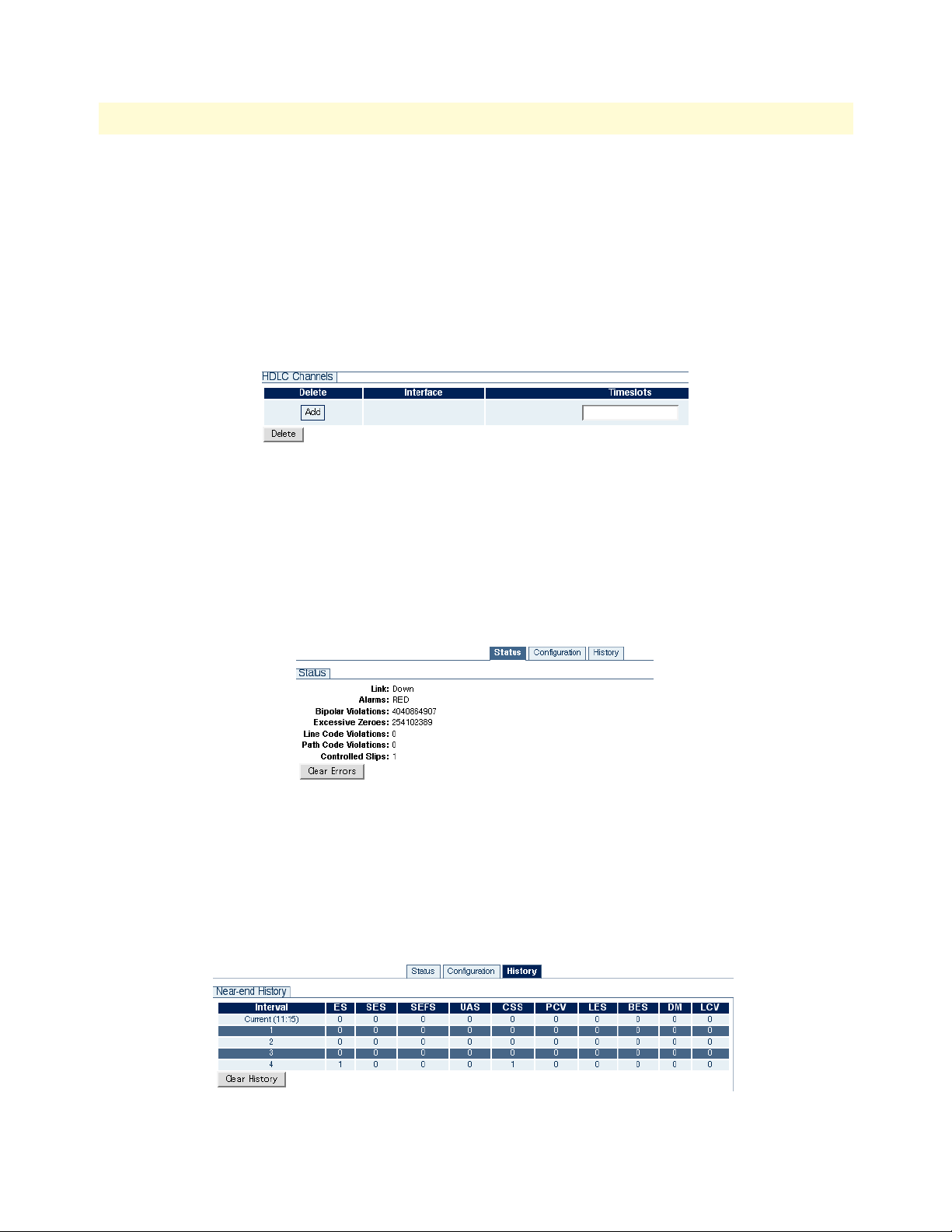
TrinityAE Administrator’s Reference Guide 10 • T1/E1 Configuration
HDLC Channels. To add an HDLC channel:
1. Enter a timeslot number in the Timeslots box in the HDLC Channels table.
2. Click the Add button in the Delete column.
To delete an HDLC channel:
1. Select the checkbox for the interface in the Delete column of the HDLC Channels table.
2. Click Delete.
Figure 37. Adding and Deleting HDLC Channels
Port Status
To view the status of a T1/E1 port:
1. Click on the link of the port that you would like to configure in the Ports table on the main T1/E1 page,
or, from a port configuration page, click on the Status tab.
2. Click Clear Errors to clear and refresh the status of a port.
Figure 38. Port Status
Port History
To view the history of a port:
1. Click on the link of the port that you would like to configure in the Ports table on the main T1/E1 page,
or, from a port configuration page, click on the History tab.
2. Click Clear History to clear and refresh the history of a port.
Figure 39. Port History
Web Management Interface (WMI) 76
Page 77

TrinityAE Administrator’s Reference Guide 10 • T1/E1 Configuration
Command Line Interface (CLI)
Configuring the Clock Source
Table 20. T1/E1 - Clock Source - CLI Commands
Command Explanation
Trinity# configure controller t1e1clock-source {internal}
Trinity# configure controller t1e1clocking source primary <port> {nofallback|fallback|fallforward}
Trinity# configure controller t1e1clocking source secondary <port>
Set the clock source as internal. All ports slave from the internal
clock.
Select a primary clock source and set the fallback mode.
Select a secondary clock source.
Trinity# configure controller t1e1clocking reset fallback
Trinity# configure controller t1e1clocking show
Trinity# show controller t1e1-clocking Show the clock settings.
Manual reset fallback. This is only valid if the fallback mode is
fallback.
Show the clocking settings.
Selecting T1 or E1 Mode
Table 21. T1/E1 - Mode - CLI Commands
Command Explanation
Trinity# configure controller t1e1
<port>
Trinity[t1e1-0]# mode {t1|e1} Select T1 or E1 mode.
Enter the configuration mode for the specified port.
Configuring T1 or E1 Applications
Table 22. T1/E1 - Applications - CLI Commands
Command Explanation
Trinity[t1e1-0]# framing
{d4|esf|clear-channel|fractional|crc}
Trinity[t1e1-0]# [no] shutdown Power up/down the port.
Trinity[t1e1-0]# line-code
{ami|b8zs|hdb3}
Trinity[t1e1-0]# application
{short-haul|long-haul}
Trinity[t1e1-0]# line-build-out
{0.0|-7.5|-15.0|-22.5}
Trinity[t1e1-0]# los-threshold
<-48 - -4>
Set the framing. D4 and ESF are valid T1 frames. Clear-channel (G.703), fractional (G.703/G.704), and CRC4 Multiframe are valid E1 frames.
Set the line code. AMI is valid for both T1 and E1. B8ZS is
valid for T1 only. HDB3 is valid for E1 only.
Select short haul (typically less than 655 feet cable) or long
haul application.
Set the transmit pulse attenuation in dB. This is used to prevent
cross-talk in the far end. This is only valid for T1 long-haul applications.
Set the loss-of-signal threshold in dB. This is only valid in longhaul applications (both T1 and E1).
Command Line Interface (CLI) 77
Page 78

TrinityAE Administrator’s Reference Guide 10 • T1/E1 Configuration
Creating HDLC Channels
Table 23. T1/E1 - HDLC Channels - CLI Command
Command Explanation
Trinity[t1e1-0]# hdlc <id> <timeslots> Map the specified timeslots to an hdlc channel, and configure
the ID. Timeslots should be specified using dashes and commas. For example, 1-3,5,7-8 specifies timeslots 1, 2, 3, 5, 7,
and 8.
Note
•
When changing between T1 and E1 modes, the HDLC channels
are no longer valid for two reasons:
– The timeslots may be invalid. For example, 1-31 is a valid
timeslot selection for E1, but not for T1.
– The same T1/E1 timeslot maps to a different timeslot internally
on the pulse-code modulation (PCM) highway.
• An HDLC channel should not be deleted if a PPP interface is
using it.
Command Line Interface (CLI) 78
Page 79

TrinityAE Administrator’s Reference Guide 10 • T1/E1 Configuration
Showing Configuration and Status
Table 24. T1/E1 - Show Configuration & Status - CLI Command
Command Explanation
Trinity[t1e1-0]# show Enter the show mode.
Trinity# show controller t1e1 0 Show the configuration, the status, and the HDLC channels.
configuration:
t1 esf (b8zs)
short-haul, 0.0 dB line build out
normal operation
status:
link up
alarms: clear
errors: lcv=0 pcv=0 lcv=0 pcv=0 cs=0
hdlc channels:
hdlc4: timeslots 1-24
Trinity[t1e1-0]# show history Show the performance history counters (most recent at the top).
ES SES SEFS UAS CSS LES BES DM
------ ------ ------ ------ ------ ------ ------ ------
1: 0 0 0 0 0 0 0 0
2: 0 0 0 0 0 0 0 0
3: 0 0 0 0 0 0 0 0
4: 0 0 0 0 0 0 0 0
5: 7 0 0 0 7 7 0 0
Command Line Interface (CLI) 79
Page 80

TrinityAE Administrator’s Reference Guide 10 • T1/E1 Configuration
Clearing Errors and Performance History
Table 25. T1/E1 - Clearing Errors - CLI Command
Command Explanation
Trinity[t1e1-0]# clear errors Clear all status for the selected port. This will clear not only
error counters, but also performance history.
Trinity[t1e1-0]# clear history Clear the performance history for the selected port, but leave
the error counters unaffected.
Using Test Modes
Table 26. T1/E1 - Test Modes - CLI Command
Command Explanation
Trinity[t1e1-0]# loopback {off|localanalog|local-digital|network}
Start or stop a loopback.The network loopback will loop data
received on the line back to the line.
Command Line Interface (CLI) 80
Page 81

Chapter 11 PPP Configuration
Chapter contents
Overview ...............................................................................................................................................................82
Configuration Overview .................................................................................................................................82
Web Management Interface (WMI) ......................................................................................................................83
Configure PPP Authentication ........................................................................................................................83
Add PPP Interfaces .........................................................................................................................................84
Status of PPP Interfaces .............................................................................................................................84
Delete PPP Interfaces ......................................................................................................................................84
Configure PPP Interfaces ................................................................................................................................85
Command Line Interface (CLI).............................................................................................................................87
PPP Authentication Commands .....................................................................................................................87
PPP Configuration Commands .......................................................................................................................87
Creating the interface ................................................................................................................................88
Configuring PPP negotiation ....................................................................................................................88
Enabling PPP on HDLC interfaces ...........................................................................................................89
Configuring LCP ......................................................................................................................................90
Configuring IPCP .....................................................................................................................................91
Configuring BCP ......................................................................................................................................92
Showing Configuration and Status ............................................................................................................93
Debugging Commands ...................................................................................................................................93
81
Page 82

TrinityAE Administrator’s Reference Guide 11 • PPP Configuration
Overview
This chapter describes how to configure PPP on the Trinity platform.
Note The menu, commands, and features for your model may vary slightly
from what is shown in this manual. Some models may not include all
of the features mentioned. Refer to the Getting Started Guide for your
device to see which features are available.
Configuration Overview
Trinity supports PPP over HDLC. Before a PPP interface can be used, there must be an HDLC channel to
which it can bind. On some models, the HDLC channels are preconfigured, whereas on others, the user must
explicitly create them.
PPP interfaces can be bridged or routed. When a PPP interface operates in bridged mode, data arriving on the
HDLC channel from a remote device is forwarded to the assigned interface (Ethernet or another bridged PPP).
When a PPP interface is operating in routed mode, data arriving on the HDLC channel is routed to the corresponding interface based on the destination IP address of the arriving packet.
To create a PPP connection, follow these steps:
1. Configure PPP Authentication (Optional)
– PPP allows one peer to demand the other to authenticate itself. The unit supports two authentication
protocols: Challenge Handshake Authentication Protocol (CHAP) and Password Authentication Protocol (PAP).
– The unit supports dial-in authentication, but not dial-out. The unit can require peers to authenticate,
but it will not authenticate itself to peers.
– PPP Authentication is performed via RADIUS. The unit passes the authentication information received
from the peer to a RADIUS server and either accepts or rejects the peer based on the RADIUS response.
– PPP authentication configuration applies to all PPP interfaces on the unit. There is no way to configure
PPP authentication on a per-interface basis.
2. Create the PPP Interface
3. Configure the PPP Interface
– Select the NCP: either IPCP or BCP.
For BCP, configure the MAC address (optional).
For IPCP, configure the local and peer IP addresses.
– Bind one or more HDLC interfaces for the PPP interface to run on top of. If more than one HDLC
interface is bound, then Multilink Protocol (MLPPP) must be used.
– Enable the PPP interface.
To configure PPP through the WMI,
see the section “Web Management Interface (WMI)” on page 83.
To configure PPP through the CLI,
see the section “Command Line Interface (CLI)” on page 87.
Overview 82
Page 83

TrinityAE Administrator’s Reference Guide 11 • PPP Configuration
Web Management Interface (WMI)
To access the PPP main page, click on Interface Configuration > PPP from the main menu on the left of the
screen.
Configure PPP Authentication
To configure PPP authentication:
1. Click on the PPP Authentication Configuration tab on the main PPP page.
2. Choose None, CHAP, or PAP from the Authentication drop-down menu.
3. Click Update.
Note When the type of authentication is changed, all PPP links that may
be up will be terminated and renegotiated with the selected authentication protocol.
The port for the RADIUS server is optional. If left blank, the default port will be used (1812 for authentication and 1813 for accounting).
Figure 40. PPP Authentication Configuration
Web Management Interface (WMI) 83
Page 84

TrinityAE Administrator’s Reference Guide 11 • PPP Configuration
Add PPP Interfaces
Figure 41. Add/Delete PPP Interfaces
To add a PPP interface:
1. On the PPP Interface Configuration page, enter the name of the interface in the Interface field. The name
for the PPP interface can be ppp<number> or just <number>.
2. Click Add.
Status of PPP Interfaces
The Status for existing PPP interfaces can be:
• <blank>: The PPP interface is not enabled.
• Down: The PPP interface is enabled, but has not completed NCP negotiation.
• Up: The PPP interface is enabled, has completed NCP negotiation, and is ready to pass traffic.
• Multilink Partially Up: The PPP interface is enabled and is ready to pass traffic on at least one, but not all,
HDLC interfaces.
• Multilink Up: The PPP interface is enabled and is ready to pass traffic on all HDLC interfaces.
Delete PPP Interfaces
To delete a PPP interface:
1. On the PPP Interface Configuration page, click the Select checkbox for the interface in the Add/Delete
PPP Interface table.
2. Click Delete.
Web Management Interface (WMI) 84
Page 85

TrinityAE Administrator’s Reference Guide 11 • PPP Configuration
Configure PPP Interfaces
To configure a PPP interface:
1. Click on the link of the interface you want to configure in the Add/Delete PPP Interfaces table on the
main PPP page.
Figure 42. Configuring a PPP interface
2. The Select Devices table shows a list of all HDLC devices, but only the devices that are not bound to
another PPP interface can be selected. The Phase of HDLC devices can be:
- <blank>: The HDLC device is not bound to a PPP interface or the PPP interface to which it is bound is
not enabled.
- Holdoff: Either negotiation failed or the link dropped causing the interface to wait for a period of time
before restarting negotiation.
- Network: LCP negotiation has completed, and either IPCP or BCP negotiation is in progress.
- Authenticate: Either CHAP or PAP negotiation is in progress.
- Running: Either IPCP or BCP negotiation has completed, and the PPP is ready to pass data over the
HDLC interface.
- Multilink Master: The HDLC interface is the multilink bundle master and is ready to pass data.
- Multilink Slave: The HDLC interface is a multilink bundle slave and is ready to pass data.
Web Management Interface (WMI) 85
Page 86

TrinityAE Administrator’s Reference Guide 11 • PPP Configuration
3. For BCP configuration, the Management-Inline checkbox specifies whether or not to attempt to negotiate
the BCP Management-Inline option. Some older PPP implementations do not respond correctly to this
option causing negotiation to fail.
4. For IPCP configuration, both local and peer IP addresses may be configured as:
- IP address specified, Accept unchecked
This causes PPP to attempt to negotiate the specified address and if the peer rejects it, then negotiation
fails.
- IP address left blank, Accept checked
This causes PPP to expect the peer to provide the IP address and if the peer does not, then negotiation
fails.
- IP address specified, Accept checked
This causes PPP to attempt to negotiate the specified address and if the peer rejects it, to accept the
address the peer provides.
Web Management Interface (WMI) 86
Page 87

TrinityAE Administrator’s Reference Guide 11 • PPP Configuration
Command Line Interface (CLI)
PPP Authentication Commands
Table 27. Steps for Configuring PPP Authentication - CLI
Command Explanation
1. Trinity# configure Enter the Configuration Mode.
2. Trinity[config]# pppauth Enter the PPP Authentication Configuration Mode.
3. Trinity[pppauth]# authentication
{none|chap|pap}
4. Trinity[pppauth]# nas-id <string> Set the NAS Identifier.
5. Trinity[pppauth]# [no] radius-server
{auth|acct} <A.B.C.D> [port <port>]
secret <string>
6. Trinity[pppauth]# show Shows the PPP authentication configuration.
Start or stop PPP authentication. If the authentication protocol changes, all PPP links that are up will terminate and
renegotiate, demanding the selected authentication protocol.
Add a RADIUS server to the list. If there is a failure
accessing a server, the list is tried in round-robin fashion.
If <port> is not specified, the default will be used (1812
for authorization and 1813 for accounting).
• Example - Trinity[pppauth]# show:
authentication: chap
nas identifier: MyIdentifier
Server Password Type
-------------------- ---------------- ----
192.168.200.2:1645 Secret auth
10.11.2.37 AnotherSecret acct
192.168.200.2 MySecret auth
PPP Configuration Commands
There are different options when creating or configuring PPP interfaces:
• “Creating the interface” on page 88
• “Configuring PPP negotiation” on page 88
• “Enabling PPP on HDLC interfaces” on page 89
• “Configuring LCP” on page 90
• “Configuring IPCP” on page 91
• “Configuring BCP” on page 92
• “Showing Configuration and Status” on page 93
Command Line Interface (CLI) 87
Page 88

TrinityAE Administrator’s Reference Guide 11 • PPP Configuration
Creating the interface
The following commands create a PPP interface:
Table 28. Steps for Creating a PPP Interface - CLI
Command Explanation
1. Trinity# configure Enter the Configuration Mode.
2. Trinity[config]# [no] ppp <id> <id> can be either ppp<number> or just <number>. This
creates interface ppp<number> and enters the PPP Configuration Mode. no ppp <id> deletes an interface.
Configuring PPP negotiation
The following commands determine when PPP will attempt to negotiate:
Table 29. Steps for Configuring PPP Negotiation - CLI
Command Explanation
1. Trinity[ppp-ppp2] [no] passive Causes the interface to wait for the peer to start negotia-
tion. no passive sets the interface to normal operation,
meaning it attempts to negotiate with the peer whether or
not the peer has started negotiation.
2. Trinity[ppp-ppp2] holdoff <seconds> During the holdoff period, no negotiation will take place.
After negotiation fails or LCP determines that the link
needs to drop (either by receiving a termination request
from the peer or by not receiving replies to echo
requests), the interface enters a holdoff period in which it
will neither send packets to nor receive packets from the
peer.
Command Line Interface (CLI) 88
Page 89

TrinityAE Administrator’s Reference Guide 11 • PPP Configuration
Enabling PPP on HDLC interfaces
The following commands specify whether the interface is enabled, and if so, over which HDLC interfaces it
will run:
Table 30. Steps for Enabling PPP on HDLC interfaces - CLI
Command Explanation
1. Trinity[ppp-ppp2] [no] shutdown Disables the PPP interface. This causes the PPP interface
to attempt to gracefully terminate the session with the
peer.
no shutdown enables the PPP interface. If the interface
was already enabled, it will terminate and then restart
using the latest configuration.
Note: Any configuration changes made to the PPP interface while it is enabled will not take effect until the no
shutdown command is executed.
2. Trinity[ppp-ppp2] [no] multilink Enables MLPPP on the interface. This allows the PPP inter-
face to bind to more than one HDLC device.
3. Trinity[ppp-ppp2] multilink min-fragsize <size>
4. Trinity[ppp-ppp2] no multilink minfrag-size
5. Trinity[ppp-ppp2] [no] bind <dev> Binds a device to an interface. <dev> must be an exist-
Configure the minimum fragment size of the first multilink
fragment.
Disable a the minimum fragment size for the first multilink
fragment.
ing HDLC device.
Unless MLPPP is enabled, all HDLC devices bound to this
interface must be unbound before binding another HDLC
device.
If MLPPP is enabled and the PPP link is up, then HDLC
devices may be added while the link is running and they
will start negotiation immediately.
Command Line Interface (CLI) 89
Page 90

TrinityAE Administrator’s Reference Guide 11 • PPP Configuration
Configuring LCP
The following commands describe how to configure LCP:
Table 31. Steps for Configuring LCP - CLI
Command Explanation
1. Trinity[ppp-ppp2] lcp Enter the LCP Configuration Mode.
2. Trinity[ppp-ppp2-lcp] echo-failure
<times>
3. Trinity[ppp-ppp2-lcp] echo-interval
<seconds>
4. Trinity[ppp-ppp2-lcp] max-configure
<times>
5. Trinity[ppp-ppp2-lcp] max-failure
<times>
6. Trinity[ppp-ppp2-lcp] max-terminate
<times>
7. Trinity[ppp-ppp2-lcp] restart <seconds> Sets the LCP retransmission timeout.
8. Trinity[ppp-ppp2-lcp] mru <mru> Requests the peer to send packets no larger than
9. Trinity[ppp-ppp2-lcp] mtu <mtu> Requests peer to accept packets at least as large as
Sets the number of unanswered LCP Echo-Requests
before the PPP interface assumes the link is down and
restarts negotiation.
PPP sends out LCP Echo-Requests and expects the peer
to send LCP Echo-Replies to determine if the link is still
up.
Sets the time between sending LCP Echo-Requests.
Sets the number of LCP Configure-Requests that the peer
does not acknowledge before restarting negotiation.
Sets the number of LCP Configure-NAKs to send before
sending LCP Configure-Rejects instead.
Sets the maximum number of LCP Terminate-Requests to
send before terminating.
<mru>.
<mtu>.
Command Line Interface (CLI) 90
Page 91

TrinityAE Administrator’s Reference Guide 11 • PPP Configuration
Configuring IPCP
The following commands describe how to configure IPCP:
Table 32. Steps for Configuring IPCP - CLI
Command Explanation
1. Trinity[ppp-ppp2] ncp ipcp Sets PPP to negotiate IPCP as the NCP.
2. Trinity[ppp-ppp2] ipcp Enter the IPCP configuration mode.
3. Trinity[ppp-ppp2-ipcp] {local|peer} ip
address {accept|<A.B.C.D>}
4. Trinity[ppp-ppp2-ipcp] [no] proxy-arp Enables responding to ARP requests for the peer.
5. Trinity[ppp-ppp2-ipcp] max-configure
<times>
6. Trinity[ppp-ppp2-ipcp] max-failure
<times>
7. Trinity[ppp-ppp2-ipcp] max-terminate
<times>
8. Trinity[ppp-ppp2-ipcp] restart <seconds> Sets the IPCP retransmission timeout.
Determines how the IP address will be assigned to the
local or peer interface.
If an IP address is specified and accept is not, then the
PPP interface will attempt to negotiate the address and
if the peer rejects, it will terminate.
If an IP address is not specified and accept is, then the
PPP interface expects the peer to provide the address
during negotiation and if the peer does not, it will terminate.
If both the IP address and accept are specified, then
the PPP interface will attempt to negotiate the address,
but if the peer rejects, it will take the address offered
by the peer.
Sets the number of IPCP Configure-Requests that the
peer does not acknowledge before restarting negotiation.
Sets the number of IPCP Configure-NAKs to send
before sending IPCP Configure-Rejects instead.
Sets the maximum number of IPCP Terminate-Requests
to send before terminating.
Command Line Interface (CLI) 91
Page 92

TrinityAE Administrator’s Reference Guide 11 • PPP Configuration
Configuring BCP
The following commands describe how to configure BCP:
Table 33. Steps for Configuring BCP - CLI
Command Explanation
1. Trinity[ppp-ppp2] ncp bcp Sets PPP to negotiate BCP as the NCP.
2. Trinity[ppp-ppp2] bcp Enter the BCP configuration mode.
3. Trinity[ppp-ppp2-bcp] mac
<XX:XX:XX:XX:XX:XX>
4. Trinity[ppp-ppp2-bcp] [no] managementinline
5. Trinity[ppp-ppp2-bcp] [no] shutdown Disables the PPP interface when negotiation com-
6. Trinity[ppp-ppp2-bcp] [no] ip address
<A.B.C.D> [netmask <A.B.C.D> [broadcast
<broadcast>]]
7. Trinity[ppp-ppp2-bcp] [no] ip address
dhcp [ignore {dns|hostname|route]
Sets the MAC address for this interface.
Negotiates the BCP Management-Inline option.
no management-inline does not negotiate the
Management-Inline option. Some older PPP implementations do not respond correctly to this option which
prevents BCP negotiation from completing.
pletes.
Adds an IP address to the PPP interface.
Enables the DHCP client on the interface.
Command Line Interface (CLI) 92
Page 93

TrinityAE Administrator’s Reference Guide 11 • PPP Configuration
Showing Configuration and Status
Table 34. Showing PPP Configuration and Status
Command Explanation
Trinity[ppp-ppp2] show Shows the PPP interface configuration and status.
• Example - Trinity[ppp-ppp2] show:
No Shutdown
Multilink: Disabled
Device(s):
hdlc2 (running)
Active
Holdoff: 30 seconds
LCP:
Echo-Failure: 10 Echo-Interval: 5 Max-Configure: 10 Max-Failure: 10
Max-Terminate: 3 Restart: 3 MRU: 1500 MTU: 1500
IPCP:
Local IP: 192.168.254.4
Peer IP: 192.168.254.5
Max-Configure: 10 Max-Failure: 10 Max-Terminate: 3 Restart: 3
ppp2 is up
Internet address 192.168.254.4/0.0.0.0 0 dhcp
MTU 1500
ARP disabled
Multicast enabled
Rx Statistics
52 bytes in 4 packets
0 errors 0 drops, 0 overruns
0 multicast packets
Tx Statistics
46 bytes in 4 packets
0 errors 0 drops, 0 collisions 0 carrier errors
Debugging Commands
Table 35. PPP Debugging Commands - CLI
Command Explanation
Trinity# debug ppp [<id>] packet Shows all PPP packets sent and received on the inter-
face, if one was specified, or else all interfaces.
Trinity# debug ppp [<id>] [priority
{emerg|alert|crit|err|warn|notice|info|
debug}]
Trinity# no debug all Turn off all debugging.
Command Line Interface (CLI) 93
Show all PPP debug messages of at least the priority
specified, emerg being the least verbose and debug
being the most. If no priority is specified, then err is
used.
Page 94

Chapter 12 HDLC Configuration
Chapter contents
Overview ...............................................................................................................................................................95
Configuration Overview .................................................................................................................................95
Web Management Interface (WMI) ......................................................................................................................96
Add/Delete HDLC Devices ............................................................................................................................96
Configure HDLC Devices ..............................................................................................................................96
Command Line Interface (CLI).............................................................................................................................97
HDLC Configuration Commands ..................................................................................................................97
HDLC Debugging Commands .......................................................................................................................97
94
Page 95

TrinityAE Administrator’s Reference Guide 12 • HDLC Configuration
Overview
This chapter describes how to configure HDLC channels.
For some TrinityAE models, the H.110 ports act as WAN ports running bridged or routed point-to-point protocol (PPP) connections over HDLC to remote devices. This chapter explains how to create HDLC channels
on that may be used to transport PPP packets.
Note The menu, commands, and features for your model may vary slightly
from what is shown in this manual. Some models may not include all
of the features mentioned. Refer to the Getting Started Guide for your
device to see which features are available
Configuration Overview
To create an HDLC channel, follow these steps:
1. Create the HDLC Channel
2. Configure the HDLC Channel
– On some models, the HDLC interface(s) transmit and receive over the H.110 bus. The H.110 bus con-
sists of 32 streams, each with 128 uni-directional timeslots. Each timeslot is uni-directional (transmit
only or receive only). Each HDLC interface must have H.110 timeslots mapped to transmit to and to
receive from before it can pass data.
To configure HDLC channels through the WMI,
see the section “Web Management Interface (WMI)” on page 96.
To configure HDLC channels through the CLI,
see the section “” on page 97.
Overview 95
Page 96

TrinityAE Administrator’s Reference Guide 12 • HDLC Configuration
Web Management Interface (WMI)
To access the HDLC page, click on Interface Configuration > HDLC from the main menu on the left of the
screen.
Figure 43. HDLC Devices main page
Add/Delete HDLC Devices
To add an HDLC device:
1. Enter the name of the device in the Device field of the Add/Delete HDLC Device table. The name for the
HDLC device can be hdlc<number> or <number>.
2. Click Add.
To delete an HDLC device:
1. Click the Select checkbox for the HDLC device in the Add/Delete HDLC Device table. (An HDLC
device cannot be deleted while it is bound to a PPP interface).
2. Click Delete.
Configure HDLC Devices
To configure an HDLC device, click on the device from the HDLC Devices table on the HDLC main page.
Figure 44. Add/Delete H.110 Maps
Enter information for the following fields:
• H.110 Stream: Must be a number in the range 1-32.
• First Timeslot: Must be a number in the range 1-128.
• Number of Timeslots: Must be a number in the range 1-128.
• Direction: Select Transmit or Receive from the drop-down menu.
An HDLC device cannot be configured while it is bound to a PPP interface.
Web Management Interface (WMI) 96
Page 97

TrinityAE Administrator’s Reference Guide 12 • HDLC Configuration
Command Line Interface (CLI)
HDLC Configuration Commands
Table 36. Steps for Creating/Configuring HDLC Devices - CLI
Command Explanation
1. Trinity# configure Enter the Configuration Mode.
2. Trinity[config]# [no] hdlc <id> <id> can be either hdlc<number> or just a number.
This creates interface hdlc<number> and enters the
HDLC Configuration Mode.
The no form of this command deletes the device. A
device cannot be deleted while it is bound to a PPP interface.
3. Trinity[hdlc-hdlc2]# [no] {tx|rx}
stream <stream> timeslots <firstts>
<numts>
4. Trinity[hdlc-hdlc2]# show Shows the configuration of the HDLC device.
Maps H.110 timeslots to the HDLC device. <stream>
must be 1-32, <firstts> must be 1-128, and <numts>
must be 1-128.
The no form of this command deletes an existing mapping. A device's H.110 mappings cannot be modified
while it is bound to a PPP interface.
Note <firstts> represents the first timeslot.
<numts> represents the number of timeslots.
Example: Trinity[hdlc-hdlc2]# show:
Direction Stream Timeslot Length
--------- ------ -------- ------
Tx 2 1 31
Rx 2 33 31
HDLC Debugging Commands
Table 37. HDLC Debugging - CLI
Command Explanation
Trinity# debug hdlc [<id>] [priority
{emerg|alert|crit|err|warn|notice|info|
debug}]
Trinity# no debug all Turn off all debugging.
Debug HDLC. If no HDLC channel id is specified, then the
entire HDLC subsystem is debugged. A priority may be
specified, emerg being the least verbose, and debug
being the most. If no priority is specified, err is used.
Command Line Interface (CLI) 97
Page 98

Chapter 13 ARP Table Management
Chapter contents
Overview ...............................................................................................................................................................99
Configuration Overview .................................................................................................................................99
About ARP Entries ....................................................................................................................................99
Web Management Interface (WMI) ....................................................................................................................100
Adding ARP Entries ......................................................................................................................................100
Deleting ARP Entries ....................................................................................................................................100
Command Line Interface (CLI)...........................................................................................................................101
Adding ARP Entries ......................................................................................................................................101
Deleting ARP Entries ....................................................................................................................................101
Displaying ARP Entries ................................................................................................................................101
98
Page 99

TrinityAE Administrator’s Reference Guide 13 • ARP Table Management
Overview
This chapter describes how to add and delete ARP entries, display the contents of the ARP Table, and flush the
ARP Table contents.
Note The menu, commands, and features for your model may vary slightly
from what is shown in this manual. Some models may not include all
of the features mentioned. Refer to the Getting Started Guide for your
device to see which features are available.
Configuration Overview
An ARP entry can be added to the table by configuring the following:
• IP address
• Interface device name
• Interface device hardware (Ethernet) address
• State
About ARP Entries
The state of an ARP entry designates whether the entry is temporary or permanent. Temporary entries are
usually the ones added to the table dynamically through address resolution. Temporary entries time-out and
are removed from the ARP table automatically. Permanent entries are the entries that are added to the table by
the user. These entries do not time-out and have to be removed explicitly by the user.
The ARP entries are displayed in a table. The table also displays the type of hardware (e.g. ethernet), a network
mask value (if one exists), and a combination of flags:
• C – Complete – Represents a valid entry; Entry has been successfully resolved.
• M – Manual/Permanent – Permanent entry added by the user.
• P – Published – The network device corresponding to the entry is advertising (publishing) its address.
- This usually happens if the network device is acting as an ARP proxy for other devices. If the device is act-
ing as an ARP proxy to a subnet of devices, the entry might have a netmask value as well.
ARP entries are deleted from the system by selecting them through the Web Management Interface (WMI), or
by using the no arp command in the Command Line Interface (CLI). The CLI also provides a flush command
to delete all entries at once. When an entry is submitted for deletion, it is not removed from the ARP table
right away. It is marked as a pending deletion and is removed if there are no active connections using it. A temporary entry might be added back to the table immediately if a new connection is established.
To configure ARP through the WMI,
see the section “Web Management Interface (WMI)” on page 100.
To configure ARP through the CLI,
see the section “Command Line Interface (CLI)” on page 101.
Overview 99
Page 100

TrinityAE Administrator’s Reference Guide 13 • ARP Table Management
Web Management Interface (WMI)
To access the ARP main page, click on Interface Configuration > ARP from the main menu on the left of the
screen.
Figure 45. ARP main page
Adding ARP Entries
To add an ARP entry:
1. Enter an IP address (dotted quad) for the entry in the IP Address box.
2. Choose an interface from the Interface drop-down menu.
3. Enter the Ethernet (Hardware) Address (<XX:XX:XX:XX:XX:XX>).
4. Select the Temporary checkbox to mark an entry as temporary (optional). The default State is permanent.
For more information on the state of an ARP entry, see the section “About ARP Entries” on page 99.
Deleting ARP Entries
The ARP Table displays all existing entries in the system. To delete an entry:
1. Select the Delete checkbox for the entry in the ARP Table.
2. Click Delete.
Figure 46. Deleting an ARP entry from the ARP table
Web Management Interface (WMI) 100
 Loading...