


Software
Configuration
Guide
SmartWare Release 2.00
Customer Deliverable Documentation
Part Number 80-0123
English
Revision 1.03, March 14, 2002


Legal Notice 3
LEGAL NOTICE
Copyright © 2001 Inalp Networks AG
All rights reserved. No part of this publication may be reproduced without prior written permission
from Inalp Networks AG.
Inalp Networks AG reserves the right to make changes in specifications and other information
contained in this document without prior notice. The information provided is subject to change
without notice.
In no event shall Inalp Networks AG or its employees and associated companies be liable for any
incidental, special, indirect or consequential damages whatsoever, including but not limited to lost
profits, arising out of or related to this manual or the information contained within it, even if Inalp
Networks AG has been advised of, known, or should have known, the possibility of such damages.
Inalp, the Inalp Logo, and SmartNode are registered trademarks of Inalp Networks AG. SmartWare
and SmartView are trademarks of Inalp Networks AG. All other trademarks mentioned in this
document are property of their respective owners.
EU Declaration of Conformity
The EU Directives covered by this Declaration
89/336/EEC Electromagnetic Compatibility Directive, amended by 92/31/EEC & 93/68/EEC
72/23/EEC Low Voltage Equipment Directive, amended by 93/68/EEC
Note: During the transition period, products may not comply with the Low Voltage Directive.
The Products covered by this Declaration
The products covered by this declaration are the SmartNode 1000 and 2000 family series devices.
The Basis on which Conformity is being Declared
The products identified above comply with the requirements of the above EU directives by meeting
the following standards:
• Safety compliance: EN 60950
• EMC compliance: EN 55022, EN 55024
• ETSI TBR3 (BRI)
• TBR4 (PRI)
The CE mark was first applied in 2000.
Inalp Networks AG
Meriedweg 7
CH-3172 Niederwangen
Software Configuration Guide, Revision 1.03

4 Table of Contents
TABLE OF CONTENTS
1 Terms and Definitions ........................................................................................................................... 14
1.1 Introduction ......................................................................................................................................14
1.2 SmartWare Architecture Terms and Definitions .........................................................................14
2 Applications ......................................................................................................................................... 21
2.1 Introduction ......................................................................................................................................21
2.2 Carrier Networks.............................................................................................................................. 21
2.3 Enterprise Networks........................................................................................................................ 22
2.4 LAN Telephony................................................................................................................................ 23
3 System Overview ................................................................................................................................ 25
3.1 Introduction ......................................................................................................................................25
3.2 SmartNode Hardware Platforms ................................................................................................... 26
3.3 SmartWare Embedded Software.................................................................................................... 27
3.4 SmartView Management Tools ...................................................................................................... 28
4 Configuration Concepts..................................................................................................................... 29
4.1 Introduction and Overview ............................................................................................................ 29
4.2 Contexts and Gateways................................................................................................................... 30
4.2.1 Context....................................................................................................................................... 30
4.2.2 Gateway..................................................................................................................................... 30
4.3 Interfaces, Ports and Bindings........................................................................................................ 30
4.3.1 Interfaces.................................................................................................................................... 30
4.3.2 Ports and Circuits..................................................................................................................... 31
4.3.3 Bindings..................................................................................................................................... 31
4.4 Profiles and Use commands ........................................................................................................... 32
4.4.1 Profiles ....................................................................................................................................... 32
4.4.2 Use Commands......................................................................................................................... 32
5 Command Line Interface ................................................................................................................... 33
5.1 Command Modes............................................................................................................................. 33
5.1.1 System Prompt.......................................................................................................................... 34
5.1.2 Navigating the CLI................................................................................................................... 35
5.2 Command Editing............................................................................................................................ 37
5.2.1 Command Help ........................................................................................................................ 37
5.2.2 The No Form ............................................................................................................................. 37
5.2.3 Command Completion............................................................................................................ 37
5.2.4 Command History.................................................................................................................... 37
5.2.5 Command Editing Shortcuts ..................................................................................................37
6 Accessing the SmartWare Command Line Interface .................................................................... 40
6.1 Introduction ......................................................................................................................................40
6.2 Warning............................................................................................................................................. 40
6.3 Accessing the SmartWare Command Line Interface Task List.................................................. 40
6.4 Accessing via the Console Port ...................................................................................................... 41
6.4.1 Console Port Procedure........................................................................................................... 41
6.5 Accessing via a Telnet Session........................................................................................................ 42
6.5.1 Telnet Procedure....................................................................................................................... 43
6.6 Log On to SmartWare...................................................................................................................... 43
6.6.1 Warning..................................................................................................................................... 44
6.7 Selecting a Secure Password........................................................................................................... 44
6.8 Configure Operators and Administrators .................................................................................... 44
6.9 Factory Preset Administrator Account.......................................................................................... 44
Software Configuration Guide, Revision 1.03

Table of Contents 5
6.10 Create an Operator Account........................................................................................................... 45
6.11 Create an Administrator Account.................................................................................................. 45
6.12 Displaying the CLI Version ............................................................................................................ 46
6.13 Display Account Information......................................................................................................... 46
6.14 Switching to Another Account....................................................................................................... 47
6.15 Checking Identity and Connected Users ...................................................................................... 47
6.16 End a Telnet or Console Port Session............................................................................................ 48
7 Establishing Basic IP Connectivity.................................................................................................. 50
7.1 Introduction ...................................................................................................................................... 50
7.2 IP Context Selection and Basic Interface Configuration Tasks.................................................. 50
7.3 Enter the IP Context, Create IP Interfaces and Assign an IP Address...................................... 50
7.4 Define IP Ethernet Encapsulation and Bind IP Interface to Physical Port ............................... 51
7.5 Activating a Physical Port............................................................................................................... 52
7.6 Display IP Interface Information ................................................................................................... 53
7.7 Delete IP Interfaces .......................................................................................................................... 53
7.8 Examples ........................................................................................................................................... 54
7.8.1 Setting Up an IP Interface on an Ethernet Port.................................................................... 54
8 System Image Handling .................................................................................................................... 56
8.1 Introduction ...................................................................................................................................... 56
8.2 Memory Regions in SmartWare..................................................................................................... 56
8.3 Boot Procedure and Bootloader ..................................................................................................... 58
8.4 Factory Configuration ..................................................................................................................... 59
8.5 Warning............................................................................................................................................. 60
8.6 System Image Handling Task List................................................................................................. 60
8.7 Display System Image Information............................................................................................... 60
8.8 Copy System Images from a Network Server to Flash Memory............................................... 61
8.9 Copy Driver Software from a Network Server to Flash Memory ............................................. 62
9 Configuration File Handling................................................................................................................ 64
9.1 Introduction ...................................................................................................................................... 64
9.1.1 Understanding Configuration Files....................................................................................... 65
9.2 Factory Configuration ..................................................................................................................... 66
9.3 Warnings........................................................................................................................................... 67
9.4 Configuration File Handling Task List ......................................................................................... 67
9.5 Copy Configurations within the Local Memory.......................................................................... 67
9.6 Replacing the Startup Configuration with a Configuration from Flash Memory................... 69
9.7 Copy Configurations to and from a Remote Storage Location.................................................. 70
9.8 Replacing the Startup Configuration with a Configuration downloaded from TFTP Server71
9.9 Displaying Configuration File Information.................................................................................. 72
9.10 Modifying the Running Configuration at the CLI....................................................................... 72
9.11 Modifying the Running Configuration Offline............................................................................ 73
9.12 Deleting a Specified Configuration ............................................................................................... 74
10 Basic System Management............................................................................................................ 76
10.1 Overview........................................................................................................................................... 76
10.2 Basic System Management Configuration Task List................................................................... 76
10.3 Setting System Information ............................................................................................................ 76
10.4 Setting the System Banner .............................................................................................................. 78
10.5 Setting Time and Date ..................................................................................................................... 79
10.6 Display Clock Information ............................................................................................................. 79
10.7 Display Time since last Restart ...................................................................................................... 80
10.8 Configuring and Starting the Web Server .................................................................................... 80
10.9 Determining and Defining the active CLI Version...................................................................... 81
10.10 Restarting The System..................................................................................................................... 81
Software Configuration Guide, Revision 1.03

6 Table of Contents
10.11 Displaying the System Event Log.................................................................................................. 82
10.12 Displaying the System Reset Log................................................................................................... 82
10.13 Controlling Command Execution.................................................................................................. 83
10.14 Displaying the Checksum of a Configuration.............................................................................. 84
11 IP Context Overview........................................................................................................................... 85
11.1 Introduction ......................................................................................................................................85
11.2 IP Context Overview Configuration Task List............................................................................. 86
11.3 Planning your IP Configuration..................................................................................................... 87
11.3.1 IP Interface Related Information............................................................................................ 87
11.3.2 Serial Interface Related Information...................................................................................... 87
11.3.3 QoS Related Information......................................................................................................... 88
11.4 Configuring Ethernet and Serial Ports .......................................................................................... 88
11.5 Creating and Configuring IP Interfaces ........................................................................................ 88
11.6 Configuring NAPT........................................................................................................................... 89
11.7 Configuring Static IP Routing ........................................................................................................ 89
11.8 Configuring RIP................................................................................................................................ 89
11.9 Configuring Access Control Lists .................................................................................................. 90
11.10 Configuring Quality of Service.......................................................................................................90
12 IP Interface Configuration............................................................................................................. 91
12.1 Introduction ......................................................................................................................................91
12.2 IP Interface Configuration Task List.............................................................................................. 91
12.3 Creating an IP Interface................................................................................................................... 91
12.4 Deleting an IP Interface ................................................................................................................... 92
12.5 Setting the IP Address and Netmask............................................................................................. 93
12.6 ICMP Message Processing .............................................................................................................. 93
12.7 ICMP Redirect Messages................................................................................................................. 94
12.8 Router Advertisement Broadcast Message................................................................................... 94
12.9 Defining the MTU of the Interface................................................................................................. 95
12.10 Configuring an Interface as a Point-to-Point Link....................................................................... 96
12.11 Displaying IP Interface Information.............................................................................................. 96
12.12 Testing Connections with the ping Command ............................................................................ 97
12.13 Examples ........................................................................................................................................... 98
12.13.1 Deleting an IP Interface Example....................................................................................... 98
13 NAPT Configuration ...................................................................................................................... 99
13.1 Overview ........................................................................................................................................... 99
13.2 Configuring Network Address Port Translation......................................................................... 99
13.3 NAPT Configuration Task List....................................................................................................... 99
13.4 Creating a NAPT Profile ............................................................................................................... 100
13.5 Adding a Static NAPT Entry ........................................................................................................ 100
13.6 Removing a Static NAPT Entry.................................................................................................... 101
13.7 Configuring an ICMP Default Server.......................................................................................... 101
13.8 Removing an ICMP Default Server .............................................................................................102
13.9 Configuring an NAPT Interface................................................................................................... 102
13.10 Display NAPT Configuration Information................................................................................. 103
14 Ethernet Port Configuration........................................................................................................ 104
14.1 Introduction ....................................................................................................................................104
14.2 Ethernet Port Configuration Task List ........................................................................................ 104
14.3 Entering the Ethernet Port Configuration Mode .......................................................................104
14.4 Configuring Medium for an Ethernet Port................................................................................. 105
14.5 Configuring Ethernet Encapsulation Type for an Ethernet Port ............................................. 106
14.6 Binding An Ethernet Port to an IP Interface............................................................................... 106
14.7 Selecting The Frame Format for an Ethernet Port ..................................................................... 107
Software Configuration Guide, Revision 1.03

Table of Contents 7
14.8 Configuring Layer 2 CoS to Service Class Mapping for an Ethernet Port ............................. 108
14.9 Adding a Receive Mapping Table Entry..................................................................................... 109
14.10 Adding a Transmit Mapping Table Entry.................................................................................. 109
14.11 Closing an Ethernet Port............................................................................................................... 110
15 Link Scheduler Configuration....................................................................................................112
15.1 Introduction .................................................................................................................................... 112
15.2 Quick References............................................................................................................................ 113
15.2.1 Setting the Modem Rate........................................................................................................ 114
15.3 Command Cross Reference .......................................................................................................... 114
15.4 Link Scheduler Configuration Task List.....................................................................................115
15.5 Defining the Access Control List Profile..................................................................................... 115
15.5.1 Packet Classification .............................................................................................................. 115
15.5.2 Creating an Access Control List........................................................................................... 116
15.6 Assigning Bandwidth to Traffic Classes.....................................................................................117
15.7 Creating a Top-Level Service Policy Profile............................................................................... 120
15.8 Specifying Source Classes or Lower Level Source Policy Profiles .......................................... 122
15.8.1 Defining Fair Queuing Weight.............................................................................................122
15.8.2 Defining the Bit-Rate ............................................................................................................. 123
15.8.3 Defining Absolute Priority.................................................................................................... 123
15.8.4 Defining the Maximum Queue Length............................................................................... 124
15.8.5 Specifying the Type-Of-Service (TOS) Field....................................................................... 124
15.8.6 Specifying the Precedence Field........................................................................................... 125
15.8.7 Specifying Differentiated Services Codepoint Marking................................................... 125
15.8.8 Specifying Layer 2 Marking.................................................................................................. 127
15.8.9 Defining Random Early Detection....................................................................................... 128
15.8.10 Discarding Excess Load..................................................................................................... 128
15.9 Devoting the Service Policy Profile to an Interface................................................................... 129
15.10 Displaying Link Arbitration Status ............................................................................................. 130
15.11 Displaying Link Scheduling Profile Information ...................................................................... 131
15.12 Enable Statistics Gathering........................................................................................................... 131
16 Serial Port Configuration ............................................................................................................ 133
16.1 Introduction .................................................................................................................................... 133
16.2 Serial Port Configuration Task List ............................................................................................. 133
16.3 Disabling an Interface.................................................................................................................... 134
16.4 Enabling an Interface..................................................................................................................... 134
16.5 Configuring the Serial Encapsulation Type ............................................................................... 135
16.6 Configuring the Hardware Port Protocol................................................................................... 136
16.7 Defining the Transmit Data Clock Edge..................................................................................... 137
16.8 Enter Frame Relay Mode .............................................................................................................. 137
16.9 Configuring the LMI Type............................................................................................................ 138
16.10 Configuring the Keepalive Interval............................................................................................. 138
16.11 Enabling Fragmentation................................................................................................................ 139
16.12 Entering Frame Relay PVC Configuration Mode...................................................................... 139
16.13 Configuring the PVC Encapsulation Type................................................................................. 140
16.14 Binding the Frame Relay PVC to IP Interface............................................................................ 141
16.15 Disabling a Frame Relay PVC ...................................................................................................... 142
16.16 Displaying Frame Relay Information.......................................................................................... 142
16.17 Examples ......................................................................................................................................... 143
16.17.1 Displaying Serial Port Information.................................................................................. 143
16.17.2 Displaying Frame Relay Information.............................................................................. 143
16.17.3 Integrated Service Access.................................................................................................. 144
17 Basic IP Routing Configuration ..................................................................................................... 147
Software Configuration Guide, Revision 1.03

8 Table of Contents
17.1 Introduction ....................................................................................................................................147
17.2 Basic IP Routing Configuration Task List...................................................................................148
17.3 Configuring Static IP Routes......................................................................................................... 148
17.4 Deleting Static IP Routes ............................................................................................................... 149
17.5 Displaying IP Route Information................................................................................................. 149
17.6 Examples ......................................................................................................................................... 150
17.6.1 Basic Static IP Routing Example........................................................................................... 150
18 Routing Information Protocol (RIP) Configuration................................................................152
18.1 Introduction ....................................................................................................................................152
18.2 Routing Protocol............................................................................................................................. 152
18.3 RIP Configuration Task List .........................................................................................................153
18.4 Enabling Send RIP.......................................................................................................................... 153
18.5 Enabling an Interface to Receive RIP........................................................................................... 154
18.6 Specifying the Send RIP Version.................................................................................................. 154
18.7 Specifying the Receive RIP Version............................................................................................. 155
18.8 Enabling RIP Learning................................................................................................................... 155
18.9 Enabling an Interface to Receive RIP........................................................................................... 156
18.10 Enabling RIP Announcing ............................................................................................................ 156
18.11 Enabling RIP Auto Summarization .............................................................................................157
18.12 Specifying The Default Route Metric .......................................................................................... 158
18.13 Enabling RIP Split-Horizon Processing....................................................................................... 158
18.14 Enabling The Poison Reverse Algorithm.................................................................................... 159
18.15 Enabling Holding Down Aged Routes ....................................................................................... 160
18.16 Displaying RIP Configuration of an IP Interface....................................................................... 160
18.17 Displaying Global RIP Information............................................................................................. 161
19 Access Control List Configuration............................................................................................. 162
19.1 About Access Control Lists........................................................................................................... 162
19.1.1 What Access Lists Do............................................................................................................. 162
19.1.2 Why You Should Configure Access Lists ........................................................................... 162
19.1.3 When to Configure Access Lists...........................................................................................163
19.1.4 Features of Access Control Lists........................................................................................... 163
19.2 Access Control List Configuration Task List.............................................................................. 164
19.3 Map Out the Goals of the Access Control List ........................................................................... 164
19.4 Create an Access Control List Profile and Enter Configuration Mode................................... 165
19.5 Add a Filter Rule to the Current Access Control List Profile................................................... 165
19.6 Add an ICMP Filter Rule to the Current Access Control List Profile ..................................... 166
19.7 Add a TCP, UDP or SCTP Filter Rule to the Current Access Control List Profile ................ 168
19.8 Bind and Unbind an Access Control List Profile to an IP Interface ........................................170
19.9 Display an Access Control List Profile........................................................................................ 172
19.10 Debug an Access Control List Profile.......................................................................................... 172
19.11 Examples ......................................................................................................................................... 173
19.11.1 Deny a Specific Subnet ...................................................................................................... 173
20 CS Context Overview ................................................................................................................... 175
20.1 Introduction ....................................................................................................................................175
20.2 CS Context Configuration Task List ............................................................................................ 176
20.3 Plan the CS Configuration ............................................................................................................176
20.4 Configure General CS Settings..................................................................................................... 178
20.5 Configure Call Routing ................................................................................................................. 180
20.5.1 Create and Configure CS Interfaces..................................................................................... 180
20.5.2 Specify Call Routing .............................................................................................................. 181
20.6 Configure Dial Tones..................................................................................................................... 181
20.7 Configure Voice over IP Parameters ........................................................................................... 181
Software Configuration Guide, Revision 1.03

Table of Contents 9
20.8 Configure ISDN Ports.................................................................................................................... 182
20.9 Configure an ISoIP VoIP Connection.......................................................................................... 182
20.10 Configure a H.323 VoIP Connection ........................................................................................... 182
20.11 Activate CS Context Configuration............................................................................................. 183
20.12 Example........................................................................................................................................... 185
20.12.1 Configure SmartNode in an Enterprise Network.......................................................... 185
21 CS Interface Configuration......................................................................................................... 193
21.1 Introduction .................................................................................................................................... 193
21.2 CS Interface Configuration Task List .......................................................................................... 194
21.3 Create and Configure CS interfaces............................................................................................. 195
21.4 Configure Call Routing ................................................................................................................. 196
21.5 Configure Digit Collection............................................................................................................ 197
21.6 Configure Direct Call Signaling on VoIP Interfaces.................................................................. 198
21.7 Specify the Port Address on VoIP interfaces.............................................................................. 199
21.8 Bind PSTN Interfaces to PSTN Ports and Create Line Hunt Groups ..................................... 200
21.9 Examples ......................................................................................................................................... 201
21.9.1 V5 Carrier Access................................................................................................................... 201
21.9.2 Q.SIG PBX Networking......................................................................................................... 203
22 Session Router Configuration ....................................................................................................206
22.1 Introduction .................................................................................................................................... 206
22.1.1 Routing Table Structure ........................................................................................................ 207
22.2 Warning........................................................................................................................................... 208
22.3 Session Router Configuration Task List...................................................................................... 208
22.4 Map out the Goals for the Session Router .................................................................................. 208
22.5 Configure the Entry Table on Circuit Interfaces........................................................................ 209
22.6 Configure Session Routing Tables............................................................................................... 209
22.6.1 Broadcast Handling in the Session Router ......................................................................... 209
22.6.2 Configure Number Prefix for ISDN Number Types......................................................... 209
22.6.3 Create a Called Party Number Routing Table ................................................................... 210
22.6.4 Create a Calling Party Number Routing Table.................................................................. 211
22.6.5 Create a Bearer Capability Routing Table .......................................................................... 212
22.6.6 Create a Time of Day Routing Table ................................................................................... 213
22.6.7 Create a Day of Week Routing Table .................................................................................. 213
22.6.8 Create a Date Routing Table................................................................................................. 214
22.7 Configure Number Manipulation Functions ............................................................................. 214
22.7.1 Create a Number Replacement Table.................................................................................. 215
22.7.2 Create Complex Number Manipulation Functions........................................................... 216
22.8 Deleting Routing Tables and Functions......................................................................................216
22.9 Activate the Session Router Configuration ................................................................................ 217
22.10 Example........................................................................................................................................... 218
22.10.1 Enterprise Network with Local Breakout and IP Carrier Access................................ 218
23 Tone Configuration ...................................................................................................................... 222
23.1 Introduction .................................................................................................................................... 222
23.2 Tone Configuration Task List....................................................................................................... 223
23.3 Configure Call-Progress-Tone Profiles ....................................................................................... 223
23.4 Configure Tone-Set Profiles.......................................................................................................... 225
23.5 Use Tone-Set Profiles..................................................................................................................... 226
23.6 Generation of Local In-Band Tones ............................................................................................. 226
23.7 Show Call-Progress-Tone and Tone-Set Profiles ....................................................................... 227
23.8 Example........................................................................................................................................... 228
23.8.1 Tone Configuration................................................................................................................ 228
24 ISDN Port Configuration ............................................................................................................ 230
Software Configuration Guide, Revision 1.03

10 Table of Contents
24.1 Introduction ....................................................................................................................................230
24.1.1 ISDN Reference Points........................................................................................................... 230
24.1.2 Possible SmartNode Port Configurations........................................................................... 231
24.1.3 ISDN UNI signalling.............................................................................................................. 232
24.2 Warnings ......................................................................................................................................... 233
24.3 ISDN Port Configuration Task List.............................................................................................. 233
24.4 Shutdown and Enable ISDN Ports............................................................................................... 233
24.5 Configure Common BRI and PRI Parameters............................................................................ 234
24.6 Configure BRI port parameters .................................................................................................... 235
24.7 Configure PRI Port Parameters .................................................................................................... 236
24.8 Example ........................................................................................................................................... 238
25 Gateway Configuration................................................................................................................ 239
25.1 Introduction ....................................................................................................................................239
25.2 Gateway Configuration Task List................................................................................................ 240
25.3 Configure Codec Selection and Fast Connect ............................................................................ 240
25.3.1 Introduction ............................................................................................................................ 240
25.3.2 Configure used Codec for an ISoIP Connection ................................................................ 241
25.3.3 Configure used Codec for an H.323 Connection and Enable Fast Connect................... 242
25.4 Configure Registration Authentication Service (RAS) in an H.323 Gateway........................ 244
25.5 Enable Q.931 tunneling for an H.323 connection....................................................................... 245
25.6 Enable the Gateway Configuration.............................................................................................. 246
25.7 Examples ......................................................................................................................................... 247
25.7.1 Branch Offices in an Enterprise Network ........................................................................... 247
25.7.2 Gatekeeper in LAN Based Telephony................................................................................. 249
26 VoIP Profile Configuration............................................................................................................. 251
26.1 Introduction ....................................................................................................................................251
26.2 VoIP Profile Configuration Task List .......................................................................................... 252
26.3 Create a VoIP Profile...................................................................................................................... 252
26.4 Enable DTMF Relay ....................................................................................................................... 253
26.5 Enable Echo Canceller ...................................................................................................................254
26.6 Enable Silence Compression......................................................................................................... 255
26.7 Configure Voice Volume............................................................................................................... 256
26.8 Configure Dejitter Buffer (Advanced)......................................................................................... 257
26.9 Enable/Disable Filters (Advanced) .............................................................................................. 260
26.10 Show VoIP Profile Configuration and Assign it to a VoIP gateway....................................... 261
26.11 Example ........................................................................................................................................... 263
26.11.1 Home Office in an Enterprise Network .......................................................................... 263
27 VoIP Debugging............................................................................................................................ 265
27.1 Introduction ....................................................................................................................................265
27.2 Debugging Strategy .......................................................................................................................265
27.3 Warning........................................................................................................................................... 266
27.4 Debugging Task List...................................................................................................................... 266
27.5 Verify IP Connectivity ................................................................................................................... 266
27.6 Verify Circuit Switch Connectivity.............................................................................................. 267
27.7 Debug ISDN Data........................................................................................................................... 270
27.8 Debug H.323 Data .......................................................................................................................... 270
27.9 Debug ISoIP Data ........................................................................................................................... 271
27.10 Debug Session Control Data......................................................................................................... 271
27.11 Debug Voice Over IP Data............................................................................................................ 272
27.12 Check Event Logs........................................................................................................................... 272
27.13 How to Submit Trouble Reports to Inalp....................................................................................273
28 SNMP Configuration.................................................................................................................... 275
Software Configuration Guide, Revision 1.03

Table of Contents 11
28.1 Simple Network Management Protocol (SNMP) ...................................................................... 275
28.1.1 Background............................................................................................................................. 275
28.1.2 SNMP Basic Components ..................................................................................................... 275
28.1.3 SNMP Basic Commands ....................................................................................................... 276
28.1.4 SNMP Management Information Base (MIB) .................................................................... 276
28.1.5 Network Management Framework..................................................................................... 276
28.2 Identification of the SmartNode 1000 and 2000 series via SNMP ........................................... 277
28.3 Warnings......................................................................................................................................... 277
28.4 SNMP Tools .................................................................................................................................... 277
28.5 SNMP Configuration Task List.................................................................................................... 277
28.6 Setting Basic System Information ................................................................................................ 278
28.7 Setting Access Community Information..................................................................................... 280
28.8 Setting Allowed Host Information .............................................................................................. 281
28.9 Specifying The Default SNMP Trap Target................................................................................ 281
28.10 Displaying SNMP Related Information...................................................................................... 282
28.11 Using the AdventNet SNMP Utilities......................................................................................... 283
28.11.1 Using the MibBrowser....................................................................................................... 283
28.11.2 Using the TrapViewer ....................................................................................................... 284
28.12 Standard SNMP Version 1 Traps................................................................................................. 287
29 SNTP Client Configuration ........................................................................................................ 289
29.1 Introduction .................................................................................................................................... 289
29.2 SNTP Client Configuration Task List.......................................................................................... 289
29.3 Selecting SNTP Time Servers ....................................................................................................... 289
29.4 Defining SNTP Client Operating Mode...................................................................................... 290
29.5 Defining SNTP Local UDP Port ................................................................................................... 291
29.6 Enabling and Disabling the SNTP Client.................................................................................... 291
29.7 Defining SNTP Client Poll Interval ............................................................................................. 292
29.8 Defining SNTP Client Constant Offset To GMT........................................................................ 292
29.9 Defining the SNTP Client Anycast Address .............................................................................. 293
29.10 Enabling and Disabling Local Clock Offset Compensation..................................................... 294
29.11 Enabling and Disabling Root Delay Compensation.................................................................. 294
29.12 Showing SNTP Client Related Information ............................................................................... 295
29.13 Debugging SNTP Client Operation............................................................................................. 295
29.14 Recommended Public SNTP Time Servers................................................................................. 296
29.14.1 NIST Internet Time Service............................................................................................... 296
29.14.2 Other Public NTP Primary (stratum 1) Time Servers ................................................... 297
29.14.3 Additional Information on NTP and a List of other NTP servers............................... 298
29.14.4 Recommended RFC ........................................................................................................... 298
30 Appendix A ........................................................................................................................................ 299
30.1 Configuration Mode Overview.................................................................................................... 299
30.2 SmartWare 2.0 Command Summary........................................................................................... 300
30.2.1 Introduction ............................................................................................................................ 300
30.2.2 Command Summary ............................................................................................................. 301
31 Appendix B......................................................................................................................................... 315
31.1 Internetworking Terms and Acronyms ...................................................................................... 315
32 Appendix C ........................................................................................................................................ 320
32.1 Used IP Ports in SmartWare 2.0................................................................................................... 320
32.2 Available Voice Codecs in SmartWare 2.00................................................................................ 321
Software Configuration Guide, Revision 1.03

12 About This Guide
ABOUT THIS GUIDE
Objectives
The objective of SmartWare Software Configuration Guide is to provide information concerning the
software configuration and setting into service of SmartNode devices and their interface cards. The
aim is to enable you to install such devices, alone or under supervision.
For detailed descriptions of the commands in the SmartWare Revision 2.00 command set, see the
SmartWare Command ReferenceGuide.
For hardware configuration information refer to the SmartNode Hardware Installation Guide.
Audience
The guide is intended primarily for the following audiences:
• Technical staff who are familiar with electronic circuitry, networking theory and have
experience as an electronic or electromechanical technician.
• System administrators with a basic networking background and experience, but who might
not be familiar with the SmartNode.
• System administrators who are responsible for installing and configuring networking
equipment and who are familiar with the SmartNode.
Document Conventions
Inalp documentation uses the conventions listed in the Table 1-1 through Table 1-3 below to express
instructions and information.
Notice Description
Note
Warning
Caution
Table 1-1: Notice Conventions
Command Description
boldface Commands and keywords are in boldface font.
boldface italic Parts of commands, which are related to elements already named by the
Helpful suggestions or references to materials not contained in this
manual.
Situation that could cause bodily injury, or equipment damage or data
loss
Situation that could put equipment or data at risk
user, are in boldface italic font.
node The leading IP address or nodename of a SmartNode is substituted with
node in boldface italic font.
italic Variables for which you supply values are in italic font
Software Configuration Guide, Revision 1.03

About This Guide 13
Command Description
[ ] Elements in square brackets ([ ]) are optional.
{a | b | c}
Table 1-2: Command Description
Example Description
SN
boldface screen
screen
< > Nonprinting characters are in angle brackets (< >), e.g. <?> which shows
# An hash sign at the beginning of a line indicates a comment line.
Table 1-3: Example Description
Alternative but required keywords are grouped in braces ({ }) and are
separated by vertical bars ( | ).
The leading SN on a command line represents the nodename of the
SmartNode
Information you enter is in boldface screen font.
Terminal sessions and information the system displays are in screen
font.
the available commands in any mode or necessary arguments of a
command.
How to Read this Guide
SmartWare is a complex and multifaceted operating system running on your SmartNode. Without
the necessary theoretical background you will not be able to understand and consequently use all the
features available. Therefore we recommend reading at least the chapters listed below to get a
general idea about SmartWare and the philosophy of contexts used for IP and circuit switching
related configuration.
• Chapter 1, “Terms and Definitions”,
• Chapter 3, “System Overview”,
• Chapter 11, “IP Context Overview” and
• Chapter 20, “CS Context Overview”
We at Inalp Networks AG, hope you find this guide useful, whether you are a novice or professional
working with SmartNode devices and SmartWare responsible for convergent telephony and
networking solutions.
E-mail your comments to the following address:
documentation@inalp.com
Software Configuration Guide, Revision 1.03

14 Terms and Definitions
1 TERMS AND DEFINITIONS
This chapter contains the terms and their definitions that are used throughout the Software
Configuration Guide for SmartWare, Release 2.00.
This chapter includes the following sections:
• Introduction
• SmartWare Architecture Terms and Definitions
1.1 Introduction
The Software Configuration Guide for SmartWare, Release 2.00 contains many terms that are relate to
specific networking technologies areas such as LAN protocols, WAN technologies, routing, Ethernet,
and Frame Relay. Moreover various terms are related to telecommunication areas, such as the
Integrated Services Digital Network (ISDN), Public Switched Telephone Network (PSTN), and Plain
Old Telephone Service (POTS).
Because a glossary for these technologies exists in Appendix B, "Internetworking Terms and
Acronyms", of this document, and because including every term for all related technologies would
prove unrealistic and burdensome, only those terms which are in some way related to the
SmartWare-specific architecture are included here.
1.2 SmartWare Architecture Terms and Definitions
In Table 1-1 terms or definitions used to describe the SmartWare architecture are alphabetically
sorted.
Term or Definiton Meaning
Administrator The person who has priviledged access to the SmartWare
CLI.
Application Download A application image is downloaded from a remote TFTP
server to the persistent memory (flash:) of a SmartNode.
Application Image The binary code of SmartWare stored in the persistent
memory (flash:) of a SmartNode.
Batchfile Script file containing instructions to download one or more
software component from a TFTP server to the persistent
memory (flash: or nvram:) of a SmartNode.
Bootloader The bootloader is a “mini” application performing basic
system checks and starting the SmartWare application. The
bootloader also provides minimal network services allowing
the SmartNode to be accessed and upgraded over the
network even if the SmartWare application should not start.
The bootloader is installed in the factory and is in general
never upgraded.
Bootloader Image The binary code of the Bootloader stored in the persistent
memory (flash:) of a SmartNode.
Software Configuration Guide, Revision 1.03

Terms and Definitions 15
Term or Definiton Meaning
Bootstrap The starting-up of a SmartNode, which involves checking
the Reset button, loading and starting the application image,
and starting other software modules, or—if no valid
application image is available—the bootloader.
Build The released software is organized as builds. Each build has
its unique identification. A build is part of a release and is
responsible to fix software bugs. See also release.
Call Routing Calls through SmartNode can be routed based on a set of
routing criteria. See also Session Router.
Call Signaling The call signaling specifies how to set up a call to the
destination SmartNode or 3
Circuit A communication path between two or more devices.
Circuit Port Physical port connected to a switching system or used for
circuit switching.
Circuit Switching The switching system in which a dedicated physical circuit
path must exist between the sender and the receiver for the
duration of the "call." Used in the conventional telephone
network.
rd
party equipment.
Codec Abbreviation for the word construct Coder and Decoder.
Voice channels occupy 64 kbps using PCM (pulse code
modulation) coding. Over the years, compression techniques
were developed allowing a reduction in the required
bandwidth while preserving voice quality. Such compression
techniques are implemented witin a Codec.
Comfort Noise Comfort noise is generated at the remote end of the silent
direction to avoid the impression that the connection is dead.
See also Silence Compression.
Command Line Interface An interface that allows the user to interact with the
SmartWare operating system by entering commands and
optional arguments. Other operating systems like UNIX or
DOS also provide CLIs.
Configuration Download A configuration file is downloaded from a remote TFTP
server via TFTP to the persistent memory (nvram:) or volatile
memory (system:)of a SmartNode.
Configuration File The configuration file contains SmartWare CLI commands,
which are used to configure the software modules of
SmartWare performing a certain functionality of the
SmartNode.
Configuration Server A central server used as a store for configuration files, which
are downloaded to or uploaded from a SmartNode using
TFTP.
Configuration Upload A configuration file is uploaded from the persistent memory
(nvram:) or volatile memory (system:) of a SmartNode via
TFTP to a TFTP server.
Software Configuration Guide, Revision 1.03

16 Terms and Definitions
Term or Definiton Meaning
Context A SmartWare context represents one specific networking
technology or protocol, e.g. IP or circuit switching.
Data Port Physical port connected to a network element or used for
data transfer.
Dejitter Buffer To compensate variable network delays, SmartWare includes
a dejitter buffer. Storing packets in a dejitter buffer before
they are transferred to the local ISDN equipment, e.g.
telephone, SmartWare converts a variable delay into a fixed
delay, giving voice a better quality. See also Jitter.
Digit Collection SmartWare supports overlap dialling. Some of the connected
devices (PBX, ISDN network, remote gateways and
gatekeepers) may however require bloc sending of the dialed
number. SmartWare collects the overlap dialed digits and
forwards them in a single call setup message
Driver Software Download A driver software image is downloaded from a remote TFTP
server to the persistent memory (flash:) of a SmartNode.
Driver Software Image The software used for peripheral chips on the main board
and optional PMC interface cards is stored in the persistent
memory (flash:) of a SmartNode.
DTMF Relay DTMF relay solves the problem of DTMF distortion by
transporting DTMF tones over low-bit-rate codecs out-ofband or separate from the encoded voice stream
Echo Canceller Some voice devices unfortunately have got an echo on their
wire. Echo cancelation provides near-end echo compensation
for this device.
Factory Configuration The factory configuration (factory-config) represents the
system default settings and is stored in the persistent
memory (nvram:) of a SmartNode.
Fast Connect A “normal” call setup with H.323 requires several TCP
segments to be transmitted, because various parameters are
negotiated. Since a normal call setup is often too slow, fast
connect is a new method of call setup that bypasses some
usual steps in order to make it faster.
Flash Memory Persistent memory section of a SmartNode containing the
Application Image, Bootloader Image and the driver
software Image.
flash: A region in the persistent memory of a SmartNode. See also
flash memory.
Gatekeeper Gatekeepers manage H.323 zones, which are logical
collections of devices such as all H.323 devices within an IP
subnet. For example gatekeepers provide address translation
(routing) for the devices in their zone.
Software Configuration Guide, Revision 1.03

Terms and Definitions 17
Term or Definiton Meaning
Gateway In SmartWare terminology a gateway refers to a special
purpose component that connects two contexts of different
types, for example the CS and the IP context. It handles
connections between different technologies or protocols.
SmartWare includes an H.323 and IsoIP gateway.
H.323 ITU-T recommendation H.323 describes terminals,
equipment and services for multimedia communication over
Local Area Networks (LAN) which do not provide a
guaranteed quality of service. H.323 terminals and
equipment may carry real-time voice, data and video, or any
combination, including videotelephony.
H.323 RAS H.323 registration authentication service (RAS) is a sub
protocol of H.323. The RAS signaling protocol performs
registration, admissions, and bandwidth changes and
disengage procedures between the VoIP gateway and the
gatekeeper.
High-Pass Filter A high-pass filter is normally used to cancel noises at the
voice coder input. See also post filter
Host Computer system on a network. Similar to node, except that
host usually implies a PC or workstation, whereas node
generally applies to any networked system, including access
servers and routers. See also node.
Hostname Name given to a computer system, e.g. a PC or workstation.
Hunt Group In the SmartNode terminology, a hunt groups allows you to
apply the interface configuration to multiple physical ports.
Within the hunt groups free channels for outgoing calls are
hunted on all available ports. In general a hunt group
represents a group of trunk lines as used for direct dialing in
(DDI).
Interface In SmartWare an interface is a logical construct that provides
higher-layer protocol and service information. An Interface
is configured as a part of a context, and is independent of a
physical port or circuit.
Interface Card An optional plug-in card offering one or more ports of a
specific physical standard for connecting the SmartNode to
the outside world.
ISDN Integrated Services Digital Network
ISDN Services ISDN Services comprise voice, data, video and
supplementary services. Supplementary services are services
available in the ISDN network, such as calling line
identification presentation (CLIP) or call waiting (CW). See
also Q.SIG
ISoIP ISDN over IP is patent pending solution of Inalp Networks
to carry ISDN services over IP networks.
Software Configuration Guide, Revision 1.03

18 Terms and Definitions
Term or Definiton Meaning
Jitter Jitter is the variation on packets arriving on a SmartNode.
See also dejitter buffer.
Mode The SmartWare CLI is comprised of modes. There are two
basic mode groups, the execution mode group and the
configuration mode group. See Chapter 5, “Command Line
Interface” for more details.
Network Management System System responsible for managing at least part of a network.
An NMS is generally a reasonably powerful and wellequipped computer, such as an engineering workstation.
NMSs communicate with agents to help keep track of
network statistics and resources.
Node Endpoint of a network connection or a junction common to
two or more lines in a network. A Node can be a router, e.g.
a SmartNode. Nodes, which vary in routing and other
functional capabilities, can be interconnected. Node
sometimes is used generically to refer to any entity that can
access a network, and frequently is used interchangeably
with device.
Nodename Name given to a SmartNode or network element.
nvram: Persistent memory section of a SmartNode containing the
startup configuration, the factory configuration and used
defined configurations.
Operator The person who has limited access to the SmartWare CLI.
PCI Local Bus The PCI Local Bus is a high performance, 32-bit or 64-bit bus
with multiplexed address and data lines. The bus is intended
for use as an interconnect mechanism between highly
integrated peripheral controller components, peripheral addin boards, and processor/memory systems.
PCM Highway A 30 channel interface connecting the switching engine with
optional interface cards containg circuit ports.
PMC The optional interface cards for SmartNode 2000 series
which are compatible to the PCI Mezzanine Card standards.
PMC Driver Software PMC driver software performs the runtime tasks on the PMC
interface card mounted in SmartNode 2000 series devices.
The PMC drivers are interface card specific and also have
build numbers. Refer to the SmartWare release notes for
PMC driver software compatibility. The PMC drivers may be
upgraded together with the SmartWare release or they can
be downloaded individually into the persistent memory
(flash:) of a SmartNode.
PMC Loader The PMC loader initialises the PMC interface card mounted
in SmartNode 2000 series of devices. It checks hardware
versions and determines if compatible PMC drivers are
available. The PMC loader may be upgraded together with
the SmartWare release.
Software Configuration Guide, Revision 1.03

Terms and Definitions 19
Term or Definiton Meaning
Port In SmartWare a port represents a physical connector on the
SmartNode.
Port Address A port address can be assigned to a CS interface to realize a
virtual voice tunnel between two nodes.
Post Filter The voice decoder output is normally filtered using a
perceptual post-filter to improve voice quality. See also
High-Pass Filter.
POTS Plain Old Telephone Service
Profile A profile provides configuration shortcutting. A profile
contains specific settings which can be used on multiple
contexts, interfaces or gateways.
PSTN Public Switched Telephone Network. Contains ISDN and
POTS
Q.931 Tunneling Q.931 tunneling is able to support ISDN services and Q.SIG
over an IP network.
Q.SIG ISDN Services comprise additional services for the Private
ISDN network such as CNIP (Calling Name Identification
Presentation), CNIR (Calling Name Identification
Restriction) etc. See also ISDN Services.
Release SmartWare is organized in releases that define the main
voice and data features of a SmartNode. Several builds can
be available from ca ertain release. See also build.
Routing Engine In SmartWare the routing engine handles the basic IP
routing.
Running Configuration The currently running configuration (running-config) for
SmartWare, which is executed from the volatile memory
(system:) on the SmartNode.
Session Router Calls through SmartNode can be routed based on a set of
routing criteria. The entity that manages call routing is called
Session Router.
Silence Compression Silence supression (or compression) detects the silent periods
in a phone conversation and stops the sending of media
packets during this periods.
Software Configuration Guide, Revision 1.03

20 Terms and Definitions
Term or Definiton Meaning
SmartNode The SmartNode is Inalp Networks networking product
available in two series:
• The SmartNode 1000 series are compact integrated
access devices for applications in SOHO or branch
office environments. They are available in a various
interface configurations supporting up to 4 voice
channels.
• The SmartNode 2000 series are modular integrated
services network nodes designed for medium and
large enterprise applications. Multiple PMC based
interface slots and a range of interface cards
provides flexibility for both LAN and WAN interface
configuration.
SmartView SmartView is a suite of element and network management
applications that enable the management integration of the
SmartNode platforms in a provider service and network
management system. SmartView ensures efficient operations
for SmartNode networks growing in size and complexity.
SmartWare SmartWare is the application software running on the
SmartNode hardware platforms. SmartWare is available in
several releases that in general support all currently available
SmartNode models.
Startup Configuration The startup configuration is stored in the persistent memory
(nvram:) and is always copied for execution to the running
configuration in the volatile memory (system:) after a system
start-up.
Switching Engine Part of the SmartNode hardware which allows software
controlled circuit switching of circuit ports.
System Image A collective term for application images and interface card
driver software, excluding configuration files.
System Memory The volatile memory, that includes the system: region,
holding the running-config for SmartWare during operation
of a SmartNode.
system: A region in the volatile memory of a SmartNode. See also
system memory.
TFTP Server A central server used for configuration up- and download,
download of application and interface card driver software,
that is accessed using TFTP.
tftp: Identification of a remote storing location used for
configuration up- and download, download of application
and interface card driver software, that is accessed using
TFTP.
Table 1-1: SmartWare Architecture Terms and Definitions
Software Configuration Guide, Revision 1.03

Applications 21
2 APPLICATIONS
This chapter provides an overview of SmartNode applications and the main elements in a
SmartNode network.
The chapter includes the following sections:
• Introduction
• Carrier networks
• Enterprise networks
• LAN telephony
2.1 Introduction
The Inalp SmartNode product family consists of highly flexible multi-service IP network devices,
which fit a range of networking applications.
To simplify the description of these applications they have grouped into three application scenarios:
1. Applications in carrier networks in which the SmartNodes are used as customer gateways or
integrated access devices at the customer premises. These applications are also called
Integrated Service Access (ISA).
2. Applications in enterprise networks in which the SmartNodes are used as WAN routers and
voice gateways for inter-site networking. These applications are also called Multiservice
Intranets (MSI).
3. Applications in LAN telephony in which the SmartNodes serve as gateways between the
LAN and the local PBX or PSTN access. These applications are also called LAN voice
gateway (LVG).
2.2 Carrier Networks
The network termination (NT) device in a multi-service IP based provider network plays a vital role.
It provides the service access point for the subscriber with respect to physical connectivity and
protocol interoperability.
Since the access bandwidth in most cases represents a network bottleneck, the NT must also ensure
traffic classification and the enforcement of service level agreements (SLA) on the access link. In
broadband access networks this NT is also called an Integrated Access Device (IAD) or customer
gateway.
The Inalp SmartNode products offer unique features as customer gateways for business services. It
provides amongst others full ISDN feature support, local switching and breakout options and mass
provisioning support.
Software Configuration Guide, Revision 1.03

22 Applications
Figure 2-1: Typical Carrier Network Application
Figure 2-1 shows the deployment of SmartNodes in carrier networks. Each subscriber site is
equipped with a SmartNode that connects the subscriber CPE on one side with the provider network
and services on the other.
Typical services in these networks are softswitch based telephony, PSTN access through V5.2
gateways, PBX networking services, and LAN interconnection.
Typical access technologies for these networks include xDSL, WLL, PowerLine and conventional
leased lines. With the use on an external modem (M) the SmartNode can connect to leased lines or
any bridged-Ethernet broadband access.
2.3 Enterprise Networks
In company owned and operated wide are networks SmartNodes can be used to converge voice and
data communications on the same IP link.
In combination with centralized services such as groupware and unified messaging the SmartNodes
provide migration and investment protection for legacy telephony systems.
Software Configuration Guide, Revision 1.03

Applications 23
Figure 2-2: Typical Enterprise Network
Figure 2-2 shows the deployment of SmartNodes in enterprise networks. Each site (headquarter,
branch or home office) is equipped with a SmartNode that connects the local LAN and telephony
infrastructure with the IP WAN and the local PSTN carrier.
2.4 LAN Telephony
With its Voice-over-IP gateway features the SmartNode can be used as a standalone gateway for
H.323 LAN voice systems such as LAN based PBXs or call centers.
A standalone gateway has performance reliability and scalability advantages compared with PC based gateway cards. In this application the SmartNode also offers a migration path to enterprise or
carrier networking.
Figure 2-3 shows the deployment of a SmartNode as a LAN voice gateway.
The PSTN connections can be scaled from a single ISDN basic rate access to multiple primary rate
lines. With Q.SIG integration in private PBX networks is also supported.
Software Configuration Guide, Revision 1.03

24 Applications
Figure 2-3: Typical LAN Telephony System
Software Configuration Guide, Revision 1.03

System Overview 25
3 SYSTEM OVERVIEW
This chapter provides an overview of the main elements of a SmartNode system.
The chapter includes the following sections:
• Introduction
• SmartNode hardware platforms
• SmartWare embedded software
• SmartView management tools
3.1 Introduction
A complete SmartNode system or network, as installed in any of the application scenarios
introduced in Chapter 2, “Applications”, is composed of three main elements plus a third-party
network infrastructure:
• The first and most obvious element is the SmartNode devices (also referred to as hardware
platforms or network nodes) that provide the physical connectivity, the CPU and DSP
resources. Throughout the range of SmartNode models all have the common characteristics
of supporting packet-routed and circuit-switched traffic equally well.
• The second, and in many aspects core element, is the embedded software running on the
SmartNode hardware platforms. The software designed by Inalp Networks AG for the
SmartNodes is termed SmartWare. This software is handled as a separate element because it
is as far as possible platform-independent and so provides the same features and
functionality throughout the complete SmartNode model range.
• The third element is the set of SmartView management tools provided to configure and
control SmartWare and SmartNodes in a network. The focus of the SmartView tools is on
assisting network administrators and operators in handling large numbers of SmartNode
devices. This complements the standard element management interfaces provided in
SmartWare.
• Finally the third-party IP network and transmission infrastructure provides IP connectivity
between the above elements. This infrastructure can range from a simple Ethernet hub or
switch to highly complex networks including multiple access technologies, backbone
transmission and services nodes.
Figure 3-1 illustrates these four elements.
Software Configuration Guide, Revision 1.03

26 System Overview
Figure 3-1: System Overview
3.2 SmartNode Hardware Platforms
The SmartNode series of devices covers a performance range varying from that suitable for small
office/home office (SOHO) applications to large corporate sites, or in terms of voice channels from 2
channels (one BRI/So) to 60 (two PRI/S2m). The SmartNodes comprise two classes:
• The SmartNode 1000 series compact devices with fixed configured on-board ports
• The SmartNode 2000 series with on-board ports plus expansion slots for individual interface
configurations using a range of optional interface cards (IC).
The basic system model of an Inalp SmartNode is depicted in Figure 3-2. Both the SmartNode 1000
and the 2000 series have three main components:
• 64k circuit switching is supported between on-board ISDN ports and on and between ISDN
and PSTN interface cards. The circuit switching engine uses dedicated hardware resources
and therefore can bypass the VoIP gateway and packet routing engine.
• Gateway (GW), which converts 64k circuits into Internet protocol (IP) packet streams and
vice versa. Voice over IP is supported according the H.323 standard and via Inalp Networks’
patented ISDN over IP (ISoIP) protocol.
• IP Router, with on-board ports and optional data interface cards. The router is QoS enabled
allowing classification, shaping and scheduling of multiple service classes.
Software Configuration Guide, Revision 1.03

System Overview 27
Figure 3-2: SmartNode System Model
For more detailed hardware information refer to the SmartNode Hardware Installation Guide.
3.3 SmartWare Embedded Software
SmartWare is the application software that runs on the SmartNode hardware platforms. SmartWare
is available in several releases that support all available SmartNode models. Refer to the SmartWare
release notes for detailed information about hardware support.
For each SmartWare release there are platform-specific build numbers. There may be more than one
build per release and platform as updates become available. Refer to the SmartWare release notes for
build numbers and build-specific enhancements and limitations.
A SmartWare build is a binary image file. A SmartWare build is usually divided into several
checksum-protected download files to improve download efficiency and security. The download to
the SmartNode is handled in sequence using a download batchfile. Refer to Chapter 8, “System Image
Handling”, for details on SmartWare image downloads.
In addition to the actual SmartWare images there are several additional embedded software
components that you will encounter:
• The boot loader is a “mini” application that performs basic system checks and which starts the
SmartWare application. The boot loader also provides minimal network services, allowing
the SmartNode to be accessed and upgraded over the network even if the SmartWare
application should not start. The boot loader is installed in the factory and is never
upgraded.
• The PMC loader initializes PMC interface cards when mounted in SmartNode 2000 series
devices. It checks hardware versions and determines whether compatible PMC drivers are
available. The PMC loader may be upgraded together with a SmartWare release.
Software Configuration Guide, Revision 1.03

28 System Overview
• PMC driver software performs the runtime tasks on PMC interface cards mounted in
SmartNode 2000 series devices. The PMC drivers are interface card specific and also have
build numbers. Refer to the SmartWare release notes for PMC driver software compatibility.
The PMC drivers may be upgraded together with a SmartWare release or they can be
downloaded individually onto the device flash memory file system.
3.4 SmartView Management Tools
SmartWare provides two standard element management interfaces:
• The Command Line Interface (CLI), which supports full online configuration and monitoring
access for the operator
• The SNMP agent and MIB, with an emphasis on inventory and alarm management for
integration in a 3
With the aid of configuration files and TFTP up and downloads, the SmartNodes can also be
managed offline using standard text editors and file systems.
A number of host-based management applications are available to facilitate the generation, editing
and maintenance of configuration files. Tools are also available for the integration of SmartNode
management into standard network management platforms such as HP OpenView.
rd
party Network Management System (NMS)
Figure 3-3: SmartNode Management System
Software Configuration Guide, Revision 1.03

Configuration Concepts 29
4 CONFIGURATION CONCEPTS
This chapter introduces the basic SmartWare configuration concepts. A good understanding of these
concepts is vital for the configuration tasks explained in the remaining chapters of this guide.
Even if you do not like to read manuals and user guides, nevertheless we strongly recommend that
you read through this chapter because it introduces the fundamental ideas behind the structure of
the command line interface. Once you understand and know this structure you will find it much
more intuitive to navigate through the CLI and configure specific features.
The chapter includes the following sections:
• Introduction and Overview
• Contexts and Gateways
• Interfaces Ports and Bindings
• Profiles and use commands
4.1 Introduction and Overview
The Inalp SmartNodes are multi-service network devices that offer high flexibility for the interworking of circuit switched and packet routed networks and services. In order to consistently
support a growing set of functions, protocols and applications, SmartWare configuration is based on
a number of abstract concepts that represent the various SmartWare components.
Figure 4-1: Configuration Concept Overview
Figure 4-1 illustrates the various elements of a complete SmartNode configuration. Each of these
elements implements one of the configuration concepts described in this chapter. The figure also
shows the relationships and associations between the different elements. The relations are specified
through bind (arrow) and use (bullet-lines) commands. For example, you need bind commands to
bind a physical port to a logical interface, and use commands to assign profiles to contexts.
Software Configuration Guide, Revision 1.03

30 Configuration Concepts
The chapter sections that follow refer to Figure 4-1 and describe the concepts and elements in more
detail.
4.2 Contexts and Gateways
4.2.1 Context
A SmartWare context represents one specific networking technology or protocol, namely IP (Internet
Protocol) or CS (circuit-switching). A context can be seen as ”virtual dedicated equipment” within
the SmartNode. For example:
• A CS context contains the circuit-switching functions of the SmartNode. It can be seen as an
embedded multiplexer or cross-connect within the SmartNode
• An IP context contains the routing functions of the SmartNode. It can be seen as a embedded
router within the SmartNode
The contexts are identified by a name, and contain the configuration commands that are related to the technology that they represent. By means of the context concept a separate configuration can be built for newly supported network layer technologies without complicating the configuration methods of existing features. For example, as bridging, ATM or FR switching become available so can a bridging, ATM; or FR context be introduced. Each context contains a number of interfaces, which build the connections to other SmartWare elements and the outside world. Figure 4-1 shows two contexts: one of type IP named “router”, and one of type CS named “switch”. This corresponds to the default configuration of all SmartNodes.
Note
SmartWare currently supports only one instance of the CS and IP context types.
Examples
The IP context named “router” can contain static routes, RIP and NAT configuration parameters. The
circuit-switching context named “switch” can contain number translations, local breakout conditions
and least-cost routing parameters.
4.2.2 Gateway
For the communication between contexts of different types the concept of a gateway is introduced. A gateway handles connections between different technologies or protocols. For example: an H.323Gateway can connect an IP context to a circuit-switching context. The gateways are each of a specific type and are identified by a name. Each named gateway contains its configuration parameters. With this concept, a separate gateway can be built for newly-supported technology such as MGCP or SIP without complicating the configuration methods of existing software parts. Figure 4-1 shows two gateways, one of type h323 named “h323gw” and one of type ISoIP named “isoipgw”.
Example
An H.323 gateway named “h323-gw” has an H.323 gateway ID and an associated gatekeeper
configuration. It is connected to the interface “ip-trunk” on the circuit-switch context “switch” and
the interface “global-wan” on the IP context “router”.
4.3 Interfaces, Ports and Bindings
4.3.1 Interfaces
The concept of an interface in SmartWare differs from that in traditional networking devices. The
traditional use of the term interface is often synonymous with port or circuit, which are physical
Software Configuration Guide, Revision 1.03

Configuration Concepts 31
entities. In SmartWare however, an interface is a logical construct that provides higher-layer protocol
and service information, such as layer 3 addressing. Interfaces are configured as part of a context,
and are independent of physical ports and circuits. The decoupling of the interface from the physical
layer entities enables many of the advanced features offered by SmartWare.
In order for the higher-layer protocols to become active, you must associate an interface with a
physical port or circuit. This association is referred to as a binding in SmartWare. Refer to the
“Bindings” section later in this chapter for more information. In Figure 4-1, the IP context shows
three interfaces and the CS context shows four interfaces. These interfaces are configured within their
contexts. The bindings shown in the figure are not present when the interfaces are configured; they
are configured later.
4.3.2 Ports and Circuits
Ports and circuits in SmartWare represent the physical connectors and channels on the SmartNode
hardware. The configuration of a port or circuit includes parameters for the physical and data link
layer such as line clocking, line code, framing and encapsulation formats or media access control.
Before any higher-layer user data can flow through a physical port or circuit, you must associate that
port or circuit with an interface on a context. This association is referred to as a binding. Refer to the
section below for an introduction to the binding concept.
Examples of SmartNode ports are: 10bT Ethernet, Serial ISDN BRI, and ISDN PRI. Ports are
numbered according to the SmartNode port numbering scheme. The port name corresponds to the
label (or abbreviation) printed on the hardware.
Example: Ethernet 0/1, Serial 0/0, BRI 3/2
Some ports may contain multiple circuits. For example serial ports can contain one or more Frame
Relay Permanent Virtual Circuits (PVC). If a port has one or more circuits configured, the individual
circuits are bound to interfaces on a context. The port itself may not be bound in that case.
Example: frame-relay pvc 112.
Figure 4-1 shows eight ports. Three ports are bound directly to an IP interface, one port has a single
circuit configured, which is bound to the IP context. Four ISDN ports are bound to CS interfaces.
4.3.3 Bindings
Bindings form the association between circuits or ports and the interfaces configured on a context.
No user data can flow on a circuit or Ethernet port until some higher-layer service is configured and
associated with it.
In the case of IP interfaces, bindings are configured statically in the port or circuit configuration. The
binding is created bottom-up, that is from the port to the interface.
In the case of CS interfaces, bindings are configured in the interface configuration. The binding is
created top-down, that is from the interface to the port. CS interfaces can bind one ore more ISDN or
PSTN ports. If more than one port is bound, the CS interface is responsible for performing channel
hunting on all bound ports. This creates a channel hunt group.
Figure 4-1 shows bindings from ports to IP interfaces and from CS interfaces to ISDN ports.
Software Configuration Guide, Revision 1.03

32 Configuration Concepts
4.4 Profiles and Use commands
4.4.1 Profiles
Profiles provide configuration shortcuts. They contain specific settings which can be used in multiple
contexts, interfaces or gateways. This concept allows to avoid repetitions of groups of configuration
commands that are the same for multiple elements in a configuration.
Figure 4-1 shows profiles that are used in the IP and CS contexts.
4.4.2 Use Commands
Use commands form the association between profiles and contexts, gateways or interfaces. For
example when a profile is used in a context all the configuration settings in that profile become active
within the context.
Software Configuration Guide, Revision 1.03

Command Line Interface 33
5 COMMAND LINE INTERFACE
The primary user interface to SmartWare is the command line interface (CLI). You can access the CLI
either via the SmartNode console port or through a Telnet session. The CLI lets you configure the
complete SmartWare functionality, in contrast to other management interfaces (SNMP, HTTP) which
are limited to a subset of the functions. CLI commands can be entered on-line or as a configuration
script in the form of a text file. The CLI also includes monitoring and debugging commands. CLI
commands are simple strings of keywords and user-specified arguments.
This chapter gives an overview of the CLI and the basic features that allow you to navigate the CLI
and edit commands effectively. The following topics are covered:
• Command Modes
• Command Editing
For detailed information on command syntax, and usage guidelines for each CLI command refer to
Chapter 1, “Command Line Interface”, in the SmartWare Command Reference Guide.
5.1 Command Modes
The CLI is comprised of modes. There are two mode groups, the exec mode group and the
configuration mode group. Within the exec mode group there are two modes: operator exec and
administrator exec. The configuration mode group contains all of the remaining modes. A command
mode is an environment within which a group of related commands is valid. All commands are
mode-specific, and certain commands are valid in more than one mode. A command mode provides
command line completion and context help within the mode. The command modes are organized
hierarchically.
The operator’s current working mode is indicated by the CLI prompt. An overview of all command
modes is given in Figure 5-1 and Table 5-1.
Appendix A contains a detailed overview of all command modes and the CLI commands that are
valid in each mode.
Software Configuration Guide, Revision 1.03

34 Command Line Interface
Figure 5-1: Command Line Modes
5.1.1 System Prompt
For interactive (on-line) sessions the system prompt is of the form
nodename>
In the operator exec mode,
Software Configuration Guide, Revision 1.03

Command Line Interface 35
nodename#
In the administrator exec mode and in the different configuration modes
nodename(mode)#
Where:
• nodename is the currently configured name of the node (SmartNode), the IP address or the
hardware type of the device that is being configured, and
• mode is a string indicating the current configuration mode, if applicable.
Example: the prompt in configuration mode, assuming the nodename SN is
SN(config)#
Table 5-1 shows the CLI commands used to enter each mode and the system prompt that is
displayed when you are working within each mode.
5.1.2 Navigating the CLI
Initial Mode
When you initiate a session you may login with either operator or administrator privileges.
Whichever login you use, on starting the CLI is always set to the operator exec (nonprivileged exec)
mode by default. This mode allows you to examine the state of the system using a subset of the
available CLI commands.
System Changes
In order to make any changes to the system, the administrator exec (privileged exec) mode must be
entered. The enable user interface command is used for this purpose. Once in administrator exec
mode, all of the system commands are available to you. The enable command is only accessible if
you are logged in as an administrator.
Configuration
To make configuration changes the configuration mode must be entered by using the configure
command in the administrator exec mode. From here the other configuration modes are accessible as
diagrammed in the overview in Figure 5-1.
Changing Modes
Within any configuration mode, the exit command brings the user up one level in the mode
hierarchy. For example, when in pvc configuration mode, typing exit will take you to framerelay
configuration mode.
The exit command terminates a CLI session when typed from the operator exec mode.
A session can also be terminated using the logout command within any mode.
Software Configuration Guide, Revision 1.03

36 Command Line Interface
Mode Name Commands Used to Access Command-Line Prompt
operator exec (user log-on) node>
administrator exec
configure
system
ic-voice
context_ip
interface
context_cs
interface_pstn
interface_isoip
enable command from operator exec
mode
configure command from
administrator exec mode
system command from configure
mode
ic voice <slot> command from system
mode
context ip [router] command from
configure mode
interface <name> command from
context_ip mode
context cs [switch] command from
configure mode
interface pstn <name> command from
context cs config mode
interface isoip <name> command
from context cs config mode
node#
node(config)#
nod (sys)#
node(ic-voice) [<slot>]#
node(ctx-ip) [router]#
node(if-ip) [<name>]#
node(ctx-cs) [switch]#
node(if-pstn) [<name>]#
node(if_isoip) [<name>]#
interface_h323
gateway_isoip
gateway_h323
port_ethernet
port_serial
framerelay
pvc
port_isdn
profile_acl
interface h323 <name> command from
context cs config mode
gateway isoip [isoip]command from
configure mode
gateway h323 [h323] command from
configure mode
port ethernet <slot> <port> command
from configure mode
port serial <slot> <port> command
from configure mode
framerelay command from port_serial
mode
pvc <dlci> command from framerelay
mode
port isdn command from configure
mode
profile acl <name>command from
configure mode
nod (if-h323) [<name>]#
node(gw-isoip) [isoip]#
node(gw-h323) [h323]#
node(prt-eth) [slot/port]#
node(prt-ser) [slot/port]#
node(frm-rel) [<name>]#
node(pvc) [<name>]#
node(prt-isdn) [<name>]#
node(pf-acl) [<name>]#
profile_napt
profile_service-policy
profile napt <name>command from
configure mode
profile policy-map <name> command
Software Configuration Guide, Revision 1.03
node(pf-napt) [<name>]#
node(pf-srvpl) [<name>]#

Command Line Interface 37
from configure mode
source
profile_voip
profile_tone-set
profile_call-progresstone
Table 5-1: Command Mode Entry and Prompts
source {class¦policy} <name>
command from profile_service-policy
mode
profile voip <name> command from
configure mode
profile tone-set <name> command
from configure mode
profile call-progress-tone command
from configure mode
node(src) [<name>]#
node(pf-voip) [<name>]#
node(pf-tones) [<name>]#
node(pf-callp) [<name>]#
5.2 Command Editing
5.2.1 Command Help
To see a list of all CLI commands available within a mode, type a question mark “?” at the system
prompt in the mode of interest. A list of all available commands is displayed. Commands that have
become available in the current mode are displayed at the bottom of the list, separated by a line.
Commands from higher hierarchy levels are listed at the top.
You can also type the question mark while in the middle of entering a command. Doing so displays
the list of allowed choices for the current keyword in the command. Liberal use of the question mark
functionality is an easy and effective way to explore the command syntax.
5.2.2 The No Form
Almost every command supports the keyword no. Typing the no keyword in front of a command
disables the function or “deletes” a command from the configuration. For example, to enable the
Session Router trace tool, enter the command debug session-router. To subsequently disable the
Session Router trace, enter the command no debug session-router.
5.2.3 Command Completion
You can use the Tab key in any mode to carry out command completion. Partially typing a command
name and pressing the Tab key causes the command to be displayed in full up to the point where a
further choice has to be made. For example, rather than typing configure, typing conf and Tab
causes the CLI to complete the command at the prompt. If the number of characters is not sufficient
to uniquely identify the command, the CLI will provide a list with all commands starting with the
typed characters. For example if you entered the string co in the configure mode and press Tab, the
selection configure, copy and context is displayed.
5.2.4 Command History
SmartWare maintains a list of previously entered commands that you can step through by pressing
the <up-arrow> and <down-arrow> keys, and then pressing <enter> to enter the command.
The show history command displays a list of the commands you can step through using the arrow
keys.
5.2.5 Command Editing Shortcuts
The SmartWare CLI provides a number of Emacs-style command shortcuts that facilitate editing of
the command line. Table 5-2 summarized the available command editing shortcuts. The syntax Ctrl-
p means press the p key while holding down the keyboard’s “Control” key (sometimes labeled Ctl or
Ctrl, depending on the keyboard and operating system of your computer).
Software Configuration Guide, Revision 1.03

38 Command Line Interface
Esc f is handled differently; press and release the “Escape” key (often labeled Esc on many
keyboards) and then press the f key.
Software Configuration Guide, Revision 1.03

Command Line Interface 39
Keyboard Description
Ctrl-p and <up-arrow> Recall previous command in the command history.
Ctrl-n and <down-arrow> Recall next command in the command history.
Ctrl-f and <right-arrow> Move cursor forward one character.
Ctrl-b and <left-arrow> Move cursor backward one character.
Esc f Move cursor forward one word.
Esc b Move cursor backward one word.
Ctrl-a Move cursor to beginning of line.
Ctrl-e Move cursor to end of line.
Ctrl-k Delete to end of line.
Ctrl-u Delete to beginning of line.
Ctrl-d Delete character.
Esc d Delete word.
Ctrl-c Quit editing the current line.
Ctrl-l Refresh (redraw) the display.
Ctrl-t Transpose characters.
Table 5-2: Command Edit Shortcuts
Software Configuration Guide, Revision 1.03

40 Accessing the SmartWare Command Line Interface
6 ACCESSING THE SMARTWARE
COMMAND LINE INTERFACE
The Inalp SmartNode products are engineered for operator network deployment, which means an
emphasis on remote management and volume deployment. SmartNode management and
configuration is therefore based on IP network connectivity. Once a SmartNode is connected to, and
addressable in, an IP network then all configuration, management and maintenance tasks can be
performed remotely.
This chapter includes the following sections:
• Introduction
• Warning
• Accessing the SmartWare Command Line Interface Task List
6.1 Introduction
This section describes the procedures for entering SmartWare commands via the command line
interface (CLI), to obtain help, to change operator mode and to terminate a session. You can access a
SmartNode in either of two ways:
• Directly, via the console port using a terminal directly connected to a SmartNode
• Remotely, via the IP network using a Telnet application
The ports available for connection and their labels are shown for each SmartNode model in the
SmartNode Hardware Configuration Guide.
Remember that the CLI supports a command history and command completion. By scrolling with
the Up and Down Arrow keys, you can find many of your previously entered commands. Another
timesaving tool is command completion. If you type part of a command and then press the “Tab”
key, the SmartWare shell will present you with either the remaining portion of the command or a list
of possible commands. These features have been described in Chapter 5, “Command Line Interface”.
6.2 Warning
Although SmartWare supports concurrent sessions via Telnet or the console port, we do not
recommend working with more than one session to configure a specific SmartNode.
6.3 Accessing the SmartWare Command Line Interface
Task List
The basic tasks involved in accessing the SmartWare command line interface are described in the
following sections. Depending on your application scenario, some tasks are mandatory while others
could be optional.
• Accessing via the Console Port
• Accessing via a Telnet Session
• Log On to SmartWare
• Selecting a Secure Password
• Configure Operators and Administrators
• Displaying the CLI Version
• Display Account Information
• Switching to another log-in Account
Software Configuration Guide, Revision 1.03

Accessing the SmartWare Command Line Interface 41
• Checking Identity and Connected Users
• Ending a Telnet or Console Port Session
6.4 Accessing via the Console Port
To access a SmartNode via its console port the host computer must be connected directly to the
console port (labelled CONSOLE) with a serial cable (see Figure 6-1). On the host a terminal
emulation application which supports the serial interface must be used.
Note: IP settings do not need to be configured if you access the SmartNode over the console port.
Figure 6-1: Setup For Initial Configuration via the Console Port
6.4.1 Console Port Procedure
Before you begin to use the CLI to enter configuration commands, carry out these five steps:
Step 1
Step 2
Step 3
Step 4
Set up the hardware as described in the Hardware Installation Guide.
Configure your serial terminal for 9600 baud, 8 data bits, no parity, 1 start bit, 1 stop
bit, and no flow control.
Connect the serial terminal to your SmartNode. Use a serial cable according to
Appendix A of the Hardware Installation Guide.
Power on your SmartNode. A series of boot messages are displayed on the terminal
screen. At the end of the boot sequence press the ’Return’ key and the login screen will
be displayed
Software Configuration Guide, Revision 1.03

42 Accessing the SmartWare Command Line Interface
Step 5
Proceed with logging in
6.5 Accessing via a Telnet Session
This is the most usual method to connect to a SmartNode. The Telnet host accesses the SmartNode
via its network interface. A host can be connected directly to the ETH 1 port (LAN) with a crossover
cable (see Figure 6-2 A) or through an Ethernet hub with two straight cables (see Figure 6-2 B).
Note: If the IP configuration of the Ethernet port (LAN port) is not known or is wrongly configured
you must use the console interface.
Figure 6-2: Setup For Initial Configuration via an Ethernet Port
The host must have a valid IP address configured in the same subnet as the SmartNode. Table 6-1
shows the default IP address and netmask of the Ethernet ports of the SmartNode.
Port IP Address Network Mask
ETH 0 10.0.0.10 255.255.0.0 / 16
ETH 1 10.1.0.10 255.255.0.0 / 16
Table 6-1: Default IP Address Configuration
Note: The default IP addresses listed in Table 6-1 apply for a particular factory configuration, but
under certain conditions your SmartNode can have different default IP addresses. Check the
SmartWare release note for more details.
Software Configuration Guide, Revision 1.03

Accessing the SmartWare Command Line Interface 43
6.5.1 Telnet Procedure
Before you begin to use the CLI to input configuration commands, carry out these six steps:
Step 1
Step 2
Step 3
Step 4
Step 5
Step 6
Set up the SmartNode as described in the Hardware Installation Guide.
Connect the host (PC) or hub to the ETH 1 (LAN) port of your SmartNode with
crossover or straight cables, according to Appendix A of the Hardware Installation Guide.
Power on your SmartNode and wait until the ’Run’ LED lights.
Be sure that the IP address and subnet mask of your host are in the same address range
as the ETH 1 (LAN) port of your SmartNode.
Open a Telnet session to the ETH 1 (LAN) port with the IP address 10.1.0.10 of your
SmartNode.
Proceed with logging in.
6.6 Log On to SmartWare
Accessing your SmartNode via the local console port or via a Telnet session will open a login screen.
The following description of the login process is based on a Telnet session scenario but is identical
when accessing via the local console port.
The opening Telnet screen is depicted in Figure 6-3. The window header bar shows the IP address of
the target SmartNode.
At the very beginning a factory preset administrator account with name administrator and an empty
password exists in SmartWare. For that reason use the name administrator after the login prompt and
simply press the Enter key after the password prompt.
Figure 6-3: Login Display
When you have successfully logged in you are in the operator execution mode, indicated by the “>”
as command line prompt. Now you may begin to enter system commands.
Note: Details on screen in Figure 6-3, such as the IP address in the system prompt and window
header bar, may be different on your SmartNodes
Software Configuration Guide, Revision 1.03

44 Accessing the SmartWare Command Line Interface
6.6.1 Warning
You are responsible for creating a new administrator account to maintain system security. Inalp
Networks accepts no responsibility for losses or damage caused by loss or misuse of passwords.
Please read the following sections to secure your network equipment properly.
6.7 Selecting a Secure Password
It is not uncommon for someone to try to hack into a network device. You as network administrator
should do everything in your power to make your network secure. Carefully read the questions
below and see if any applies to you:
1. Are your passwords comprised of (or in any combination of) a pet’s name, birthdays or
names of friends or family, your license plate number, social security number, your favorite
number, color, flower, animal, etc.?
2. Do you use the same password repeatedly? (Example: Your ATM PIN, cell phone voice mail,
house alarm setting code, etc.)
3. Could your password or a portion thereof be found in the dictionary?
4. Is your password less than six characters long?
To prevent unauthorized access you should select passwords that are not dictionary words or any of
the above-mentioned examples. Every password should be at least 6 characters long and include at
least one capital letter, one number, and one lowercase letter.
A good example of a password is: 3Bmshtr
Right now you are probably asking yourself, “How am I going to remember that?” It’s easy, the
password above is an acronym taken from: “3
password is that easy! But please, don’t use the above example password for your SmartNode
device.
blind mice see how they run”. Making a good
6.8 Configure Operators and Administrators
To secure the system, as well as to enable remote access to the system, you must create operator and
administrator login accounts. These accounts are valid system-wide. Operators and administrators
are allowed to log in directly to the console and through Telnet.
Because of security reasons you have to define new administrator and operator accounts, depending
on your employees and their responsibilities. For more details check the SmartWare Command
Reference Guide.
Note: Only administrators are allowed to create new administrator and operator accounts.
6.9 Factory Preset Administrator Account
As mentioned in Paragraph 6.6, “Log On to SmartWare”, at the very beginning a factory preset
administrator account with name administrator and an empty password exists in SmartWare. After
adding a new administrator account, the factory preseted administrator account will be
automatically deleted and only the newly created administrator account is available. It is possible to
create more than one administrator account. There has to be at least one administrator account
defined. If for any reason the very last administrator account is deleted, the factory preset
administrator account with name administrator and an empty password is recreated automatically by
SmartWare.
Software Configuration Guide, Revision 1.03

Accessing the SmartWare Command Line Interface 45
6.10 Create an Operator Account
Operators do not have privileges to run the enable command and therefore cannot modify the
system configuration. Operators are able to view partial system information.
Creating a new operator account needs the following procedure:
Procedure
Create an operator account.
Mode
Operator execution
Command Purpose
Step 1 node>enable
Step 2 node#configure
Step 3 node(cfg)# operator name password password
Sep 4 copy running-config startup-config
Example: Create an Operator Account
The following example shows the commands used to add a new operator account with a login name
“support” and a matching password of “s4DF&qw”. The changed configuration is then saved.
SN>enable
SN#configure
SN(cfg)#operator support password s4DF&qw
SN(cfg)#copy running-config startup-config
Enters administration execution mode
Enters configuration mode
Creates new operator account name and
password password
The change made to the running
configuration of the SmartNode is
saved, so that it will be used following
a reload
6.11 Create an Administrator Account
Administrators can run the enable command and access additional information within the
SmartWare configuration modes. Therefore administrators can modify the system configuration, as
well as view all relevant system information.
Creating a new administrator account needs the following procedure:
Procedure
Create an administrator account.
Mode
Operator execution
Command Purpose
Step 1 node>enable
Software Configuration Guide, Revision 1.03
Enters administration execution mode

46 Accessing the SmartWare Command Line Interface
play
Step 2 node#configure
Step 3 node(cfg)# administrator name password
password
Step 4 node(cfg)#copy running-config startup-
config
Example: Create an Administrator Account
The following example shows the commands used to add a new administrator account with a login
name “super” and a matching password of “Gh3*Ke4h”.
SN>enable
SN#configure
SN(cfg)#administrator super password Gh3*Ke4h
SN(cfg)#copy running-config startup-config
Enters configuration mode
Creates new administrator account
name and password password
Permanently stores the new
administrator account parameters.
6.12 Displaying the CLI Version
Procedure
To display the version of the currently running SmartWare CLI
Mode
Operator execution
Command Purpose
Step 1 node>show version cli
Example: Displaying the CLI Version
The following example shows how to display the version of the current running SmartWare CLI on
your device, if you start from the operator execution mode.
SN>show version cli
CLI version : 2.00
Displays CLI version
6.13 Display Account Information
The show command in SmartWare can be used to display information about existing administrator
and operator accounts. This command is not available for an operator account.
Displaying account information needs the following procedure:
Procedure
Display user account(s).
Mode
Administrator execution
Command Purpose
Step 1 node#show accounts
Dis
s the currently-configured administrator and
Software Configuration Guide, Revision 1.03

Accessing the SmartWare Command Line Interface 47
operator accounts
Example: Display Account Information
The following example shows how to display information about existing administrator and operator
accounts.
SN#show accounts
administrator accounts:
super
operator accounts:
support
6.14 Switching to Another Account
To switch from one user account to working in another the su command is used. With this command
a user can change from his current account to another existing account ‘name’. After executing su
with the account name to which the user wants to change as argument, the password of the
particular account has to be entered to get priviledged access.
Procedure
To switch from your current working account to another account.
Mode
Administrator or operator execution
Command Purpose
Step 1 node>su account-name
Example: Switching to Another Account
The following example shows how to change from your current user account to an administrator
account, starting from operator execution mode. In the example below the who command is used to
check the identity within both accounts
login: support
password: <password>
SN>who
You are operator support
SN>su super
Enter password: <password>
SN>who
You are administrator super
Change to the user user account account-name
6.15 Checking Identity and Connected Users
To display who is logged in or to see more detailed information about users and process states the
who command provides this information. Depending on execution mode the command displays
varying information. In administrator execution mode the command output is more detailed and
shows information about the ID, user name, state, idle time and location. In operator execution mode
only the user name being used at the moment is reported, which helps checking the identity.
Procedure
To report who is logged in or to show more detailed information about users and process states,
depending on the execution mode working in
Software Configuration Guide, Revision 1.03

48 Accessing the SmartWare Command Line Interface
Mode
Administrator or operator execution
Command Purpose
Step 1 node#who
node>who
Example: Checking Identity and Connected Users
The following example shows how to report who is logged in or more detailed information about
users and process states, depending on the execution mode working in.
Used in administrator execution mode:
Note: The “*” character idetifies the identity of the user executing the who command. ID represents
the ID of the account. State represents the actual running condition of the user, which can be logout,
login, exec and config.
Used in operator execution mode:
or or
SN#who
ID User name State Idle Location
* 0 administrator exec 00:00:00 172.16.224.44:1160
1 support exec 00:01:56 172.16.224.44:1165
SN>who
You are operator support
Shows more detailed information about the users ID,
name, state, idle time and location
Shows the user login identity
6.16 End a Telnet or Console Port Session
To end a Telnet or console port session you use the logout command in the operator or
administration execution mode. To confirm the logout command you have to enter “yes” on the
dialog line as show in the example below.
Procedure
To terminate a session
Mode
Operator execution
Command Purpose
Step 1 node>logout
Example: End a Telnet or Console Port Session
The following example shows how to terminate a session from the administrator execution
configuration mode.
SN>logout
Press 'yes' to logout, 'no' to cancel :
Software Configuration Guide, Revision 1.03
Terminates session after a confirmation by user.

Accessing the SmartWare Command Line Interface 49
After confirming the dialog with “yes” the Telnet session to the SmartNode is terminated and the
Telnet application window on your host closes.
Note: Using the command exit in the operator execution mode also terminates a Telnet or console
port session, but without any confirmation dialog.
Software Configuration Guide, Revision 1.03

50 Establishing Basic IP Connectivity
7 ESTABLISHING BASIC IP
CONNECTIVITY
This chapter explains how to establish network-based connections to and from your SmartNode
using IP interfaces and Ethernet ports. Configuring basic IP connectivity is carried out in both the
context IP and the subsidiary interface command modes. For a complete description of the IP context
and interface configuration related commands referred to in this chapter, see Chapter 11, “IP Context
Overview”, and Chapter 12, “IP Context Overview” in this guide. Moreover refer to Chapter 15,
“Interface Mode”, in the SmartWare Command Reference Guide for IP Interface related command
descriptions.
The chapter includes the following sections:
• Introduction
• IP Context Selection and Basic Interface Configuration Tasks
• Examples
7.1 Introduction
The predefined IP context in SmartWare contains the functionality of a classic IP router. Within the
IP context packets are routed between IP interfaces in accordance with the routing table. The
following sections guide you through all the steps necessary to establish network-based IP
connectivity to and from your SmartNode.
7.2 IP Context Selection and Basic Interface Configuration
Tasks
The basic tasks involved in configuring an IP context, the related interfaces and ports are:
• Enter the IP Context, Create IP Interfaces and Assign an IP Address
• Define IP Ethernet Encapsulation and Bind IP Interface to a Physical Port
• Activate the Physical Port
• Display IP Interface Information
• Delete IP Interfaces
After you have entered the IP context and performed the basic configuration tasks, configuration of
additional protocols and services such as RIP, ICMP and NAPT is possible for your IP context.
7.3 Enter the IP Context, Create IP Interfaces and Assign
an IP Address
The SmartWare application software running on your SmartNode has a predefined IP context, which
has to be selected for the configuration procedure. An IP interface name can be any arbitrary string of
not more than 25 characters. Use self-explanatory names for your IP interfaces which reflect their
usage. Each IP interface needs its explicit IP address and an appropriate netmask to be set.
Procedure
To enter the IP context, create an IP interface and assign an IP address with appropriate netmask
Mode
Configure
Software Configuration Guide, Revision 1.03

Establishing Basic IP Connectivity 51
Command Purpose
Step 1 node(cfg)#context ip router
Step 2 node(ctx-ip)[router]#interface
name
Step 3 node(if-ip)[name]#ipaddress
ip-address netmask
Example: Enter IP Context, Create IP Interfaces and set IP Address and Netmask
The procedure below assumes that you want to create an IP interface named lan, with an IP address
of 192.168.1.3 and a netmask of 255.255.255.0. Use the following commands in configuration mode to
select the IP context and create the IP interface.
SN(cfg)#context ip router
SN(ctx-ip)[router]#interface lan
SN(if-ip)[lan]#ipaddress 192.168.1.3 255.255.255.0
Enters the predefined IP context configuration mode.
Creates the new interface name, which represents an
IP interface. This command also places you in
interface configuration mode for the interface name
you have just created.
Sets the IP address ip-address and netmask netmask for
interface name
7.4 Define IP Ethernet Encapsulation and Bind IP Interface
to Physical Port
Before an IP interface is accessible the IP Ethernet encapsulation has to be defined for the related
port. It is assumed that you would like to define IP Ethernet encapsulation for port port on slot slot.
Before an IP interface can be used, it needs to be bound to a physical port of your SmartNode. The
SmartNode has one or more expansion slots that can have one or more ports. Specifying a port
unambiguously means that you must define the slot in which it is located. We assume you would
like to bind the IP interface name to port port of slot slot.
Procedure
To define IP Ethernet encapsulation for a port and bind IP interface to a port
Mode
Configure
Command Purpose
Step 1 node(cfg)#port ethernet slot
port
Step 2 node(prt-
eth)[slot/port]#encapsulation
ip
Step 3 node(prt-eth)[slot/port]#bind
interface name router
Enters port configuration mode and selects the
Ethernet port port on slot slot, on which IP Ethernet
encapsulation shall be used and to which an IP
interface shall be bound.
Sets IP Ethernet encapsulation for port port on slot
slot
Binds interface name to port port on slot slot to the IP
context named router, which is the IP router context
Software Configuration Guide, Revision 1.03

52 Establishing Basic IP Connectivity
Example: Define IP Ethernet Encapsulation and Bind IP Interface to Physical Port
We assume you would like to set IP encapsulation for Ethernet port 0 on slot 0 and bind the already
defined IP interface lan to the same physical port. Use the following commands in port Ethernet
mode.
SN(ctx-ip)[router]#port ethernet 0 0
SN(prt-eth)[0/0]#encapsulation ip
SN(prt-eth)[0/0]#bind interface lan router
7.5 Activating a Physical Port
After all the settings for the IP interface are completed the physical port has to be activated. The
SmartWare default status for any port is disabled. In the SmartWare terminology any port is in the
shutdown state unless it is activated by command.
Using the command show port ethernet slot port lists the actual status for the selected physical port.
The following listing shows the port Ethernet information for port 0 on slot 0, which is in the
shutdown state as indicated by CLOSED for the current state.
SN(prt-eth)[0/1]#show port ethernet 0 0
Ethernet Configuration
-------------------------------------
Port : ethernet 0 0 0
State : CLOSED
MAC Address : 00:30:2B:00:1D:D4
Speed : 10MBit/s
Duplex : Half
Encapsulation : ip
Binding : wan@router
Frame Format : standard
Default Service: 0
To activate a port for operation the shutdown status of the port has to be removed. That means, the
state of the port has to be changed to OPENED. To activate a physical port use the no shutdown
command in port configuration mode.
Command Purpose
Step 1 node(ctx-ip)[router]#port
ethernet slot port
Step 2 node(prt-eth)[slot/port]#no
shutdown
Example: Activating the Phyiscal Port
We assume you would like to activate the physical port 0 on slot 0, for which you use the following
commands in port configuration mode.
SN(cfg)#port ethernet 0 0
SN(prt-eth)[0/0]#no shutdown
Enters port configuration mode and selects the
Ethernet port port on slot slot, which is to be activated
Activates the physical port port on slot slot for
operation
Software Configuration Guide, Revision 1.03

Establishing Basic IP Connectivity 53
At this point your SmartNode has a running IP interface on Ethernet port 0 on slot 0, which uses IP
encapsulation.
7.6 Display IP Interface Information
Information for all the configured IP interfaces can be displayed by the show command. The
command lists relevant information for every IP interface. The IP interfaces are identified by the
name.
Procedure
To displays IP interface information
Mode
Configure
Command Purpose
Step 1 node(cfg)#show ip interface
Example: List existing IP Interfaces
Displaying IP interface information using the show ip interface command in configuration mode. In
the following example only the information available for IP interface lan is displayed. Depending on
the number of defined IP interfaces the output of the show ip interface command can be longer.
SN(ctx-ip)[router]#show ip interface
…
------------------------------------------------------------
Context: router
Name: lan
IP Address: 192.168.1.3 255.255.255.0
P2P: point-to-point
MTU: 1500
ICMP router-discovery: enabled
ICMP redirect: send only
State: OPENED
Binding: ethernet 0 0 0/ethernet/ip
…
An easy way to list existing interfaces is by using the interface command followed by a “?” in the IP
context configuration mode, which creates a list of all the defined IP interfaces.
SN(cfg)#context ip router
SN(ctx-ip)[router]#interface <?>
<interface> New interface
external Existing interface
internal Existing interface
lan Existing interface
wan Existing interface
Displays IP interface information
7.7 Delete IP Interfaces
Deleting an existing interface in the IP context is often necessary. The procedure illustrated below
assumes that you would like to delete the IP interface name. Use the no argument to the interface
command as in the following demonstration in IP context configuration mode.
Procedur e
To delete an existing IP interface
Software Configuration Guide, Revision 1.03

54 Establishing Basic IP Connectivity
Mode
Context IP
Command Purpose
Step 1 node(ctx-ip)[router]#no
interface name
Example: Delete IP Interfaces
The illustrated procedure below assumes that you would like to delete the IP interface named
external. Use the following commands in IP context mode.
First list the existing interfaces:
SN(ctx-ip)[router]#interface <?>
<interface> New interface
external Existing interface
internal Existing interface
lan Existing interface
wan Existing interface
Now delete the interfaces named “external” with the no interface command with the interface name
as argument:
SN(ctx-ip)[router]#no interface external
Finally list the interfaces again to check if the IP interface external has been deleted:
SN(ctx-ip)[router]#interface <?>
<interface> New interface
internal Existing interface
lan Existing interface
wan Existing interface
Deletes the existing IP interfaces name
7.8 Examples
7.8.1 Setting Up an IP Interface on an Ethernet Port
The following example shows all required configuration steps, which end in an activated IP interface
on Ethernet port 0 on slot 0. Figure 7-1 below shows the relation between the IP interface lan and the
Ethernet port 0 on slot 0. The configuration procedure below starts in the operator execution mode:
Software Configuration Guide, Revision 1.03

Establishing Basic IP Connectivity 55
Figure 7-1: Relation between IP Interface lan and Ethernet port 0 on slot 0
First the context IP mode is selected for the required IP interface configuration.
SN>enable
SN#configure
SN(cfg)#context ip router
After that a new interface lan is created, for which both the IP address and netmask are specified.
SN(ctx-ip)[router]#interface lan
SN(if-ip)[lan]#ipaddress 192.168.1.3 255.255.255.0
Next the Ethernet port 0 on slot 0 is selected, the medium is set to 10 Mbit/s in half-duplex mode, and
IP encapsulation for this port is chosen.
SN(if-ip)[lan]#port ethernet 0 0
SN(prt-eth)[0/0]#medium 10 half
SN(prt-eth)[0/0]#encapsulation ip
Afterwards the just defined interface lan is bound to the Ethernet port, and then the port is activated.
SN(prt-eth)[0/0]#bind interface lan router
SN(prt-eth)[0/0]#no shutdown
As a final point the configuration settings are stored in the startup configuration so as to be available
after the next system reboot.
SN(prt-eth)[0/0]#copy running-config startup-config
Software Configuration Guide, Revision 1.03

56 System Image Handling
8 SYSTEM IMAGE HANDLING
This chapter describes how to load and maintain system images and driver software. System images
contain the application image and driver software images. The application image represents the
software running SmartWare, which has to be stored in the persistent region of the memory. Driver
software images contain software that also has to be stored in the persistent region of the memory
and are used for optional PMC interface cards. Refer to Chapter 3, “Administrator Execution Mode”,
in the SmartWare Command Reference Guide for a complete description of the commands related to
this chapter.
This chapter includes the following sections:
• Introduction
• Memory Regions in SmartWare
• Boot Procedure and Bootloader
• Factory Configuration
• Warnings
• System Image Handling Task List
8.1 Introduction
All Inalp Networks SmartNode devices are shipped with a default system image, which is stored in
the persistent flash memory of the SmartNode at the Inalp Networks AG factory. The system image
contains the application image and driver software images that together build SmartWare. In
addition a factory configuration is loaded to the SmartNode at the Inalp Networks AG factory, which
initially parameterizes SmartWare. Therefore the user is neither has to load a system image not the
factory configuration to the SmartNode prior using it.
Your own operational configuration files are stored in the SmartNode flash memory, and copies may
also be stored on a remote server. Transferring configuration files between the flash memory and a
remote server requires the use of the Trivial File Transfer Protocol (TFTP). The TFTP server must be
accessible through one of the SmartNode IP interfaces. TFTP is not possible over the console
interface.
In the following sections the focus is on SmartWare memory regions and the software components
that can be copied within the memory or moved between a TFTP server and the memory of the
SmartNode. Since SmartWare uses a specific vocabulary in naming those software components, refer
back to Chapter 1, “Terms and Definitions”, to ensure that you understand the concepts.
8.2 Memory Regions in SmartWare
The SmartNode memory used by SmartWare is divided into several regions as shown in Figure 8-1
below. A remote TFTP server is used for up- or downloading configurations, application and driver
software images to or from the SmartNode’s memory. In the SmartWare command syntax, the file
path of a file on the TFTP server that is used for image up- or download is prefixed with tftp:
followed by the absolute file path starting from the root directory of the TFTP server.
The flash memory stores data contained in it persistently and is made up of two logical regions
called flash: and nvram:, which are used as follows:
• The application image, a bootloader image and one or more driver software images have to
be stored in the logical region flash: of flash memory.
Software Configuration Guide, Revision 1.03

System Image Handling 57
• Configuration files have to be stored in the logical region nvram: of the flash memory. The
factory default configuration is always loaded, and may be restored by pressing the
SmartNode reset button; see the Hardware Configuration Guide. The startup, or user-specific
configuration, is also stored in nvram.
The factory configuration is read-only, and is contained in the persistent memory in the logical
region nvram: of the SmartNode. It can be used if no user-specific configuration is available to startup SmartWare with a minimal functionality. This configuration is named “factory-config” in the
SmartWare terminology. A dedicated user-specific configuration has to be created and stored in the
flash memory. This configuration defines the user’s desired system functionality and is used to startup the system under normal conditions. This configuration has to be stored as “default-config” in the
logical region nvram: of flash memory. Any configuration stored within the persistent memory in the
logical region nvram: can be copied to a remote server using TFTP.
Since configurations are not executable from persistent memory, any configuration that is to be used
has to be copied into the volatile memory of the SmartNode prior to operation. This procedure takes
place after the system bootstrap, where the application image (i.e. SmartWare) is started and a
configuration must be available. Shortly before SmartWare is fully started up the configuration
“startup-config” is copied from the logical region nvram: of flash memory as the “running-config”
into the volatile memory system: of the SmartNode. The volatile memory system: is a logical region
within the random access memory (RAM) of the SmartNode.
Changing any settings during operation of a SmartNode alter the running configuration, i.e. that
named “running-config” in the volatile memory system:. In order to have such modifications
available after the next system start, the running configuration must to be stored back as “startupconfig” to the persistent memory nvram:. Furthermore it is possible to backup the “running-config”
in the volatile memory system: with a user-defined name in persistent memory nvram: or on a remote
TFTP server.
Software Configuration Guide, Revision 1.03
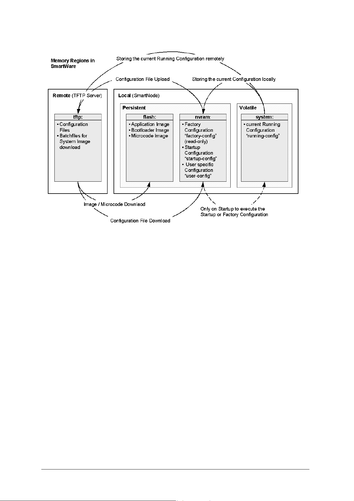
58 System Image Handling
Figure 8-1: SmartNode Memory Regions Logically Defined in SmartWare
8.3 Boot Procedure and Bootloader
During a normal boot procedure of a SmartNode the bootstrap application checks the persistent
memory in the logical region nvram: for an application image. Following that the application image is
executed, that is SmartWare is started module by module. Shortly before SmartWare is fully started
up the configuration “startup-config” is copied from the logical region nvram: of flash memory as
“running-config” into the volatile memory system: and is used to parameterize SmartWare. Figure
8-2 illustrates the boot procedure.
Software Configuration Guide, Revision 1.03

System Image Handling 59
Figure 8-2: Boot Procedure
There are two situations during bootstrap during which the bootloader takes control. The bootstrap
application checks the status of the Reset button on the back plane of the SmartNode, and if the
system button has been pressed it launches the bootloader. The bootloader is also launched if a valid
application image is not available.
The bootloader ensures that basic operations, network access and downloads are possible in cases of
interrupted or corrupted application image downloads. When the bootloader is started, the LED
ACT is blinking on the front panel of the SmartNode to display this state. When downloading an
application image the bootstrap only switches to the newly loaded application image if it is valid.
Otherwise the bootstrap will still use the previous application image if the download was not
successful.
If the application image is valid it is started, and SmartWare is brought into operation module by
module. During this system initialization phase the status of the Reset button on the back plane of
the SmartNode is checked. If the button has been pressed the factory configuration is loaded into the
volatile memory and is used to parameterize SmartWare. If the button has not been pressed the
startup configuration is loaded into the volatile memory and is used to parameterize SmartWare.
8.4 Factory Configuration
Inalp SmartNodes are delivered with a factory configuration stored in the logical region nvram: of the memory. It is used to initially parameterize the network and component settings of SmartWare, which make sense at the very beginning. Moreover if a SmartWare is malfunctioning resetting to the initial state is done by reloading the factory configuration. The factory configuration consists of:
• Default settings for the IP networking subsystem,
Software Configuration Guide, Revision 1.03

60 System Image Handling
• Default settings for H.323 and ISoIP gateway subsystem, and
• Default settings for the quality of service subsystem
As soon as a user-specific configuration is created and stored as startup configuration, the factory
configuration will no longer used but it remains in the persistent memory.. At any time during
operation of a SmartNode it is possible to switch back to the factory configuration. The restoration
procedure for restoring the default settings is described in the companion volume Hardware
Installation Guide.
8.5 Warning
Avoid downloading any system image if you do not completely understand what you have to do!
8.6 System Image Handling Task List
To load and maintain system images perform the tasks described in the following sections:
• Display System Image Information
• Copy System Images from a Network Server to Flash Memory
• Copy driver software from a Network Server to Flash Memory
8.7 Display System Image Information
Procedure
To display information about system images and driver software
Mode
Administrator execution
Command Purpose
show version
Example: Display System Image Information
The following example shows the information that is available for a SmartNode 2000 series device
with an optional IC-4BRV interface card mounted in slot 2.
SN#show version
Product name : SN2300
Software Version : SmartWare R2.00 BUILD22031
Supplier :
Provider :
Subscriber :
Information for Slot 0:
SN2300 (Admin State: Application Started, Real State: Application
Started)
Hardware Version : 1, 1
Serial number : 100000021579
PLD Version : 23010204h
Software Version : SmartWare R2.00 BUILD22031
Information for Slot 1:
Lists the system software release version, information about
optional interface cards mounted in slots, and other
information.
Software Configuration Guide, Revision 1.03

System Image Handling 61
this Slot is empty
Information for Slot 2:
IC-4BRV (Admin State: Application Started, Real State: Kernel
Started)
Hardware Version : 1
PLD Version : 170001h
Software Version : Build 24026, min required : Build 24027
Loader Version : Build 39, min required: Build 39
Information for Slot 3:
this Slot is empty
8.8 Copy System Images from a Network Server to Flash
Memory
As mentioned above the system image file contains the application software that runs SmartWare; it
is loaded in the flash memory at the Inalp Networks factory. Since most of the voice and data
features of the SmartNode are defined and implemented within the application software, upgrading
to a new release might be necessary if you want to have additional voice and data features available.
A new system image file has to be stored permanently into the flash memory of your SmartNode to
be present when booting the device.
Since the system image file is preloaded at the Inalp Networks factory, you will only have to
download new SmartWare application software if a major software upgrade is necessary or if
recommended by Inalp Networks. Under normal circumstances downloading a system image file
should not be needed.
Downloading a new system image file means storing it permanently at a defined location within the
SmartNode flash memory. To store the system image file a special download script file has to be
used. This script file defines how the system image file is to be handled and where it is to be stored.
You cannot download any system image file without an appropriate script file.
Each line in script file is a command for the CLI of your SmartNode. To download a system image
file, which will replace the currently running SmartWare application software, a script file with only
one command is necessary.
Comment lines must have a hash character # in column one and can appear anywhere in the script
file. Comment lines contain information for administrators or operators who maintain or use the
script file.
The following example shows a script file used to download a system image and command line
syntax definition file from a TFTP server.
# script file for system image download
# Inalp Networks AG. 2001-10-24
image.bin 1369474 21; ver 2300.1,2300.2;
cli.xml
+/flash/cli/spec.xml
#the next line deletes the whole embedded file system
*UÊDä
Note: The script file includes a 32-bit CRC on the last line, displayed as four characters when seen in
an ordinary text editor. Do not delete the line containing the CRC entry or the download will fail!
Software Configuration Guide, Revision 1.03

62 System Image Handling
The script file is downloaded with the copy commands. The copy command source defines the TFTP
path to the script file and the target is set use the script parser. After downloading the script file the
system image file and command line syntax definition file download is started automatically.
Note: When encountering problems due to memory exhaustion (message "Parsing batch
file...% APP - OUT OF MEMORY.") shutdown the H.323 gateway prior to initiating the
download command as follows (which will temporarily free the required memory):
SN(cfg)#gateway h323 h323
SN(gw-h323)[h323]#shutdown
After the successful download either issue the 'reload' command (in order to start the IPNode with
the new software) or restart the H.323 gateway thus enabling calls again (with the current software):
SN(cfg)#gateway h323 h323
SN(gw-h323)[h323]#no shutdown
Procedure
To download a script file
Mode
Administrator execution
Command Purpose
Step 1 node(cfg)# copy tftp://node-ip-adress/b
flash:
Example: Copy System Images from a Network Server to Flash Memory
The following example shows how to download the system image file and command line syntax
definition file from the TFTP server at IP address 172.16.36.80. The download is defined by a script
file, which has to be downloaded first. After downloading the script file the system image file and
command line syntax definition file are downloaded automatically.
SN>enable
SN#configure
SN(cfg)#copy tftp://172.16.36.80/sn2300/BUILD22032/b flash:
Completed image download
Completed file download /flash/cli/spec.xml
SN(cfg)#
Downloads the script file b from the TFTP
server at address node-ip-address and starts
the system image download process. This
progress is visualized with a counter,
counting up from 0 to 100% according to
the downloaded amount of the file size for
each file that needs to be downloaded.
8.9 Copy Driver Software from a Network Server to Flash
Memory
Driver software images contain driver software that is to be downloaded to hardware devices such
as optional interface cards.
Software Configuration Guide, Revision 1.03

System Image Handling 63
Downloading a driver software image file means storing it permanently at a defined location within
the flash memory on the motherboard or in the non-volatile memory of an optional interface card. To
download driver software image file a special download script file must be used.
The following example shows a script file used to download a driver software image file from a
TFTP server for an IC-4BRV interface card.
# script file for driver software image download
# Inalp Networks, Inc. 2001-10-24
;
/IC-4BRVoIP_Vx_R2.00_BUILD24028
+/flash/bin/pmc000216a6
4¼—
This script file defines how the driver software image file is to be handled and where it is to be
stored.
Note: You cannot download any driver software image file without an appropriate script file.
Procedure
To download a driver software image file
Mode
Administrator execution
Command Purpose
Step 1 node(cfg)# copy tftp://node-ip-adress/b flash:
Example: Copy Driver Software from a Network Server to Flash Memory
The following example shows how to download the driver software image file from the TFTP server
at IP address 172.16.36.80. The download is defined by a script file, which has to be downloaded first.
After downloading the script file the driver software image file is downloaded automatically.
SN>enable
SN#configure
SN(cfg)#copy tftp://172.16.36.80/IC-4BRVoIP/BUILD24028/b flash:
Completed file download /flash/bin/pmc000216a6
SN(cfg)#
Downloads the script file b from the
TFTP server at address node-ip-address
and starts the driver software image
download process. This progress is
visualized with a counter, counting up
from 0 to 100% according to the
downloaded amount of the file size for
each file that needs to be downloaded.
Software Configuration Guide, Revision 1.03

64 Configuration File Handling
9 CONFIGURATION FILE HANDLING
This chapter describes how to up- and download configuration files from and to a SmartNode 1000
or 2000 series devices. A configuration file is a batch file of SmartWare commands that are used
within the software modules that are performing specific functions of the SmartNode. Some aspects
of configuration file management are also described in this chapter. Refer to Chapter 4,
“Administrator Execution Mode” in the SmartWare Command Reference Guide for a complete
description of the commands related to this chapter. See also Chapter 8, “System Image Handling”,
of this document.
This chapter includes the following sections:
• Introduction
• Factory Configuration
• Warnings
• Configuration File Handling Task List
9.1 Introduction
All Inalp Networks SmartNode devices are shipped with a factory configuration file which is stored
in the flash memory of the SmartNode.
A configuration file is like a script file containing SmartWare commands that can be loaded into the
system. Configuration files may also contain only partial configurations. This allows you to keep a
library of command sequences that you may want to use as required. By default the system
automatically loads the factory configuration from the flash memory if no user-specific configuration
is defined as the startup configuration.
Changing the current running configuration is possible as follows:
• You may change the running configuration interactively. Interactive configuring requires
that you access the CLI using the enable command to enter administrator execution mode.
Then you must switch to the configuration mode by typing the command configure. Once in
configuration mode you can enter the configuration commands that are necessary to
configure your SmartNode.
• You can also create a new configuration file or modify an existing one offline. Configuration
files can be copied from the SmartNode flash memory to a remote server. Transferring
configuration files between the flash memory and a remote system requires the trivial file
transfer protocol (TFTP). The TFTP server must be reachable through one of the SmartNode
network interfaces.
See Chapter 6, “Accessing the SmartWare Command Line Interface”, of this document for
information concerning access to the CLI.
In the following sections the emphasis is on SmartWare memory regions and on software
components that can be copied within the memory or be up/downloaded between a TFTP server and
the memory of the SmartNode. Since SmartWare uses a specific vocabulary in naming those software
components, refer back to Chapter 1, “Terms and Definitions”, to ensure that you understand the
concepts. Moreover re-read Chapter 8, “System Image Handling”, for a basic understanding of how
SmartWare uses system memory.
Software Configuration Guide, Revision 1.03

Configuration File Handling 65
9.1.1 Understanding Configuration Files
Configuration files contain SmartWare commands that are used to customize the functionality of
your SmartNode device. During system startup the SmartWare command parser reads the factory or
startup configuration file command-by-command, organizes the arguments and dispatches each
command to the command shell for execution. If, during operation of a SmartNode, you enter a
command using the CLI of SmartWare, you alter the running configuration accordingly. In other
words you are modifying a live, in-service system configuration.
Figure 9-1 below shows the characteristics of a configuration file. This configuration is stored on a
TFTP server in the file SN2300_001.cfg for later download to the SmartNode SN. The command
syntax is identical for commands entered by the use of the CLI and commands contained in
configuration files. For better comprehension SmartWare allows comments within configuration
files. To add a line with a comment to your configuration file simply begin the line with the hash (#)
character. The command parser skips everything after the hash character to the end of the line.
#----------------------------------------------------------------#
# SmartNode IP and Voice configuration #
#----------------------------------------------------------------#
# #
# Node: SN #
# Config: SN2300_001.cfg #
# Model: SN2300 0001-0001 #
# Serial No.: 100000021579 #
# Administrator: LB #
# Date: 12/10/2001 #
# #
#----------------------------------------------------------------#
# SNTP configuration used for time synchronization
cli version 2.00
sntp-client
sntp-client server primary 172.16.1.10 port 123 version 4
sntp-client poll-interval 600
sntp-client gmt-offset + 01:00:00
# system definitions
system
clock-source 1 2
hostname SN
# IP context configuration
context ip router
route 0.0.0.0 0.0.0.0 172.19.32.2 1
route 172.19.41.0 255.255.255.0 172.19.33.250
route 172.19.49.0 255.255.255.0 172.19.33.250
multicast-send default-interface lan
# CS context configuration
context cs switch
no number-prefix national
no number-prefix international
use tone-set-profile default
called-party rtab 201 dest-interface telecom-operator
called-party rtab 202 dest-interface telecom-operator
no shutdown
# interface LAN used for connection to internal network
interface lan
ipaddress 172.19.33.30 255.255.255.0
Software Configuration Guide, Revision 1.03

66 Configuration File Handling
mtu 1500
# interface WAN used for connection to access network
interface wan
ipaddress 172.19.32.30 255.255.255.0
mtu 1500
# interface used to access the PSTN telecom operator
interface pstn pstn-operator
routing dest-interface h323
bind port 1 0
# interface used to access the VoIP telecom provider
interface h323 voip-provider
routing dest-table rtab
remoteip 172.19.33.60
# H.323 gateway primarily used
gateway h323
codec g711alaw64k 10 20
codec g711ulaw64k 10 20
faststart
no ras
gatekeeper-discovery auto
bind interface lan router
use voip-profile default
no shutdown
port ethernet 0 0
medium auto
encapsulation ip
bind interface lan router
no shutdown
port ethernet 0 1
medium 10 half
encapsulation ip
bind interface wan router
no shutdown
Figure 9-1: Sample Configuration File
Each configuration file that is stored in the flash memory needs a unique name. The user has to
assign a file name to any user-specific configuration. SmartWare predefines some names for
configuration files. These are the file names used to represent the factory configuration, startup
configuration and running configuration, which are factory-config, startup-config and running-config.
Refer back to Chapter 1, “Terms and Definitions”, to learn more about configuration file types.
9.2 Factory Configuration
Inalp SmartNodes are delivered with a factory configuration in the logical region nvram: of the SmartNode that is used to initially parameterize the network and component settings of SmartWare that are most useful when starting initially. Moreover, if a SmartWare is malfunctioning, resetting to the initial state is possibleby reloading the factory configuration. The factory configuration consists of:
• Default settings for the IP networking subsystem,
• Default settings for H.323 and ISoIP gateway subsystem, and
• Default settings for the quality of service subsystem
Software Configuration Guide, Revision 1.03

Configuration File Handling 67
As soon as a user-specific configuration is created and stored as the startup configuration, the factory
configuration is no longer used, but still remains in the persistent memory. At any time during the
operation of a SmartNode it is possible to switch back to the factory configuration. The restoration
procedure for restoring the default settings is described in the companion volume Hardware
Installation Guide.
9.3 Warnings
Avoid downloading any configuration file if you do not completely understand what you have to
do! If a configuration file download fails or succeeds only partially your SmartNode device cannot
start up without a support intervention at the Inalp Networks factory.
9.4 Configuration File Handling Task List
This Section describes how to create, load, and maintain configuration files. Configuration files
contain a set of user-configured commands that customize the functionality of your SmartNode
device so as to suit your own operating requirements.
The tasks in this chapter assume that you have at least a minimal configuration running on your
system. You can create a basic configuration file using the configure command; see Chapter 9.10,
“Modifying the Running Configuration at the CLI”, in this guide for details.
To display, copy, delete, and down- or upload configuration files perform the tasks described in the
following sections:
• Copy Configurations within the Local Memory
• Replacing the Startup Configuration with a Configuration from Flash Memory
• Copy Configurations to and from a Remote Storing Location
• Replacing the Startup Configuration with a Configuration downloaded from TFTP Server
• Displaying Configuration File Information
• Modifying the Running Configuration at the CLI
• Modifying the Running Configuration Offline
• Deleting a Specified Configuration
9.5 Copy Configurations within the Local Memory
Configuration files may be copied within the local memory in order to switch between different
configurations. Remember the different local memory regions in SmartWare as shown in Figure 9below.
In the majority of cases, the interactively modified running configuration known as the running-
config, which is to be found in the volatile memory region system:, is copied to the persistent memory
region nvram:. This running config is stored under the name startup-config and replaces the existing
startup configuration.
The current running configuration can be copied to the persistent memory region nvram: under a
user-specified name, if that configuration is to be preserved.
In addition, an already existing configuration is usually copied to the persistent memory region
nvram: using a user-specified name, for conservation or later activation.
Software Configuration Guide, Revision 1.03
2

68 Configuration File Handling
Figure 9-2: Local Memory Regions in SmartWare
As shown in Figure the local memory regions are identified by their unique names, like nvram:
which is located in flash memory and system:, which is the system RAM, i.e. the volatile memory. As
already mentioned, within the same memory region any configuration file needs a unique name so
for example it is not possible to have two configurations files with the name running-config in the
memory region nvram:.
As you might expect, the copy command does not move but replicates a selected source to a target
configuration file in the specified memory region. Therefore the source configuration file is not lost
after the copy process. There are three predefined configuration files names for which the
specification of the memory region is optional, namely the files factory-config, startup-config and
running-config.
Procedure
To copy a specified configuration with another name in local memory
Mode
Administrator execution
Command Purpose
9-2
Step 1 node#copy {factory-config | startup-config
| running-config | nvram: source-name }
nvram:target-name
Copies the selected source configuration
file source-name as target configuration
file target-name in local memory.
Software Configuration Guide, Revision 1.03

Configuration File Handling 69
Example: Backing Up the Startup Configuration
The following example shows how to make a backup copy of the startup configuration. In a first step
the startup-config is copied under the name backup within the flash memory region nvram:.
SN#copy startup-config nvram:backup
9.6 Replacing the Startup Configuration with a
Configuration from Flash Memory
The startup configuration is replaced by a configuration that is already present in the flash memory,
by copying it to that area of the flash memory where the startup configuration is to be stored.
Procedure
To replace the startup configuration with another present in flash memory
Mode
Administrator execution
Command Purpose
Step 1 node# copy nvram:new-startup startup-config
Replaces the existing persistent startup
configuration with the startup
configuration new-startup already
present in flash memory.
Note: It is assumed that the configuration new-startup that is present in flash memory was previously
copied to the flash memory, e.g. from a TFTP server using the copy command.
Example: Replacing the Startup Configuration with a Configuration from Flash Memory
The following example shows how to overwrite and therefore replace the persistent startup
configuration in the flash memory of a SmartNode with the configuration contained in the file new-
startup already present in the flash memory.
Step 1
First replace the current startup configuration, using the copy command, into the flash memory area
where the startup configuration has to be stored.
SN#copy nvram:new-startup startup-config
Step 2
Check the content of the persistent startup configuration by listing its command settings with the
show command.
SN#show startup-config
Startup configuration:
#----------------------------------------------------------------#
# SmartWare R2.00 BUILD22031 #
# 2001-10-25T09:20:42 #
# Generated configuration file #
#----------------------------------------------------------------#
cli version 2.00
Software Configuration Guide, Revision 1.03

70 Configuration File Handling
snmp community public rw
…
framerelay
exit
SN#
9.7 Copy Configurations to and from a Remote Storage
Location
Configuration Files may be copied from local memory (persistent or volatile region) to a remote data
store. Remember the different store locations; they are the local memory in your SmartNode and the
remote data store on a server system. See Figure 9-3. A remote storage location is mostly used to
store ready configurations for later download to a certain SmartNode. A TFTP server has to be used
as a remote data store. From within SmartWare this remote TFTP server is represented by the
memory region tftp: in combination with the IP address of the TFTP server and the name and path of
the configuration file. We will explain the usage of the remote memory region tftp: in the following
section more detailed. Another typical task is uploading the current running configuration to the
remote data store for backup purpose, or if an extensive configuration file is to be edited on the
remote host. In this case the running configuration, named running-config, which is to be found in the
volatile memory region system: is transferred to the TFTP server. On the TFTP server the running
configuration is stored to a file whose name is defined as one of the arguments of the copy
command.
Figure 9-3: Remote Memory Regions for SmartWare
Finally configuration files, i.e. the startup configuration or a user-specific configuration that is stored
in the persistent memory region nvram: are often uploaded to the remote data store for backup, edit
Software Configuration Guide, Revision 1.03

Configuration File Handling 71
or cloning purposes. The latter procedure is very helpful when you have several SmartNode devices
each using a configuration which does not greatly differ from the others, or which is the same for all
devices. During the configuration of the first SmartNode according to your requirements, the
running configuration of this device, named running-config and which is to be found in the volatile
memory region system: is edited. Next the configuration is tested and if everything is as required, the
running configuration is copied as startup configuration, named startup-config, to the persistent
memory region nvram: of the target device. After this the startup configuration is transferred to the
TFTP server from where it can be distributed to other SmartNode devices, which therefore get clones
of the starting system if the configuration does not need any modifications.
9.8 Replacing the Startup Configuration with a
Configuration downloaded from TFTP Server
From within the administration execution mode, the startup-configuration is replaced by
downloading a configuration from the TFTP server into the flash memory area where the startup
configuration has to be stored.
Procedure
To copy a specified configuration with another name in flash memory
Mode
Administrator execution
Command Purpose
Step 1 node(cfg)# copy tftp://ip-adress/new-startup
nvram:startup-config
Example of Configuration download from TFTP Server
The following example shows how to overwrite and therefore replace the persistent startup
configuration in the flash memory of a SmartNode with the configuration contained in the file new-
startup located on the TFTP server at IP address 172.16.36.80.
Step 1
First download the startup configuration with the copy command into the flash memory area where
the startup configuration is to be stored.
SN>enable
SN#configure
SN(cfg)#copy tftp://172.16.36.80/user/new-startup nvram:startup-
config
Download...100%
SN(cfg)#
Downloads the configuration file newstartup from the TFTP server at address
ip-address replacing the existing
persistent startup configuration. This
progress is visualized with a counter,
counting up from 0 to 100% according
to the downloaded amount of the file
size. If the download should fail an
error message “% FileTransfer - Get
failed” is displayed.
Software Configuration Guide, Revision 1.03

72 Configuration File Handling
Step 2
Check the content of the persistent startup configuration by listing its command settings with the
show command.
SN#show nvram:startup-config
Startup configuration:
#----------------------------------------------------------------#
# SmartWare R2.00 BUILD22031 #
# 2001-10-25T09:20:42 #
# Generated configuration file #
#----------------------------------------------------------------#
cli version 2.00
snmp community public rw
…
…
framerelay
exit
SN#
9.9 Displaying Configuration File Information
Procedure
To display information about configuration files
Mode
Administrator execution
Command Purpose
show nvram: List of all persistent configurations
show running-config Displays the contents of the running configuration file
show startup-config Displays the contents of the startup configuration file
9.10 Modifying the Running Configuration at the CLI
The SmartWare accepts interactive modifications on the currently running configuration via the CLI.
Interactive configuring needs access to the CLI. Use the enable command to enter administrator
execution mode, and then switch into the configuration mode by typing the command configure.
Once in configuration mode you can enter the configuration commands that are necessary to your
SmartNodes operating. When you configure SmartWare using the CLI, the shell executes the
commands as you enter them.
When you log-in to a SmartNode using the CLI all commands entered directly modify the running
configuration, which is located in the volatile memory region system: (or RAM) of your SmartNode.
Remember that this memory is - as its name suggests - volatile, therefore if your modifications shall
be permanent you have to copy the configuration to the persistent memory. In most cases you will
store it as the upcoming startup configuration and therefore store it in the persistent memory region
nvram: under the name startup-config. On the next start-up the system will initialize itself using the
modified configuration. As a final step the SmartNode has to be restarted using the reload
command.
Software Configuration Guide, Revision 1.03

Configuration File Handling 73
Procedure
To modify the running configuration at the CLI and store it as the startup configuration
Mode
Administrator execution
Command Purpose
Step 1 node#configure
Step 2
Step 3 node(cfg)#copy running-config startup-
config
Step 4 node(cfg)#reload
Example: Modifying the Running Configuration at the CLI
The following example shows how to modify the currently running configuration via the CLI and
save it as the startup configuration.
SN#configure
SN(cfg)#…
SN(cfg)#copy running-config startup-config
SN(cfg)#reload
Press 'yes' to restart, 'no' to cancel : yes
The system is going down
Enters administrator configuration
mode
Enter all the necessary configuration
commands.
Saves the running configuration file as
upcoming startup configuration
Restarts the system
9.11 Modifying the Running Configuration Offline
In cases of complex configuration changes, which are easier to do offline, a SmartNode’s running
configuration may be stored on a TFTP server and there edited and saved. Since the SmartNode is
acting as a TFTP client, all file transfer operations are initiated from the SmartNode.
First the running configuration, named running-config, has to be uploaded from the SmartNode to the
TFTP server. After that the configuration file located on the TFTP server gets edited using any
regular text editor. Followed by downloading the configuration back to the SmartNode as upcoming
startup configuration and therefore store it in the persistent memory region nvram: under the name
startup-config. Finally the SmartNode has to be restarted using the reload command to activate the
changes.
Note: Consider that a user-specific configuration file does not manipulate any function of SmartWare
until it is copied to - and therefore replaces - the configuration file startup-config. Downloading
configuration files to flash memory using a name other then startup-config is typically useful to
activate any configuration changes or to store configuration for backup purposes in the flash
memory of the SmartNode.
Procedure
The procedure necessary to modify the running configuration offline
Mode
Administrator execution
Software Configuration Guide, Revision 1.03

74 Configuration File Handling
Command Purpose
Step 1 node#copy running-config tftp://node-ip-
adress/current-config
Step 2
Step 3 node#copy tftp://node-ip-adress/current-
Offline editing of the configuration file
config nvram: startup-config
Uploads the current running configuration
as file current-config to the TFTP server at
address node-ip-address. This progress is
visualized with a counter, counting up
from 0 to 100% according to the
downloaded amount of the file size. If the
upload should fail an error message “%
FileTransfer - Put failed” is displayed.
current-config on the TFTP server using any
regular text editor.
Downloads the modified configuration file
current-config from the TFTP server at
address node-ip-address into the persistent
memory region nvram: using the name
startup-config. This progress is visualized
with a counter, counting up from 0 to 100%
according to the downloaded amount of
the file size. If the download should fail an
error message “% FileTransfer - Get failed”
is displayed.
Step 4 node#reload
Example: Modifying the Running Configuration Offline
The following example shows the commands used to upload the running configuration from the
SmartNode to the file current-config on a TFTP server at IP address 172.16.36.80. The uploaded
configuration file will be written into the root directory specified by the TFTP server settings, and
overwrites any existing file with the same name. Read your TFTP server manual to get a thorough
understanding of its behavior. After this the configuration file is available for offline editing on the
TFTP server. Following the modified configuration file current-config is downloaded from the TFTP
server, at IP address 172.16.36.80, to the SmartNode’s persistent memory region nvram: using the
name startup-config. Finally the SmartNode has to be restarted.
SN#copy running-config tftp://172.16.36.80/user/current-config
Upload...100%
At this point in time the offline editing of the configuration file current-config on the TFTP server
takes place.
SN#copy tftp://172.16.36.80/user/ current-config nvram:startup-config
Download...100%
SN#reload
Press 'yes' to restart, 'no' to cancel : yes
The system is going down
Restarts the system
9.12 Deleting a Specified Configuration
You can delete configuration files from the SmartNode flash memory region nvram:.
Software Configuration Guide, Revision 1.03

Configuration File Handling 75
Procedure
To delete a specified configuration in flash memory
Mode
Administrator execution
Command Purpose
Step 1 node#show nvram:
Step 2 node#erase name
Example: Deleting a Specified Configuration
The following example shows how to delete a specific configuration from among a set of three
available configurations in Flash memory. The configuration named “isoip-config” is to be deleted,
since it is no longer used.
Step 1
First the command show nvram: is used with to list all available configurations.
SN#show nvram:
Persistent configurations:
backup
minimal
startup-config
factory-config
Step 2
Next the configuration named minimal has to be deleted explicitly.
SN#erase nvram:minimal
Lists the loaded configurations
Deletes the configuration name from flash memory.
Step 3
The command show nvram: is entered again to check if the selected configuration was deleted
successfully from the set of available configurations.
SN#show nvram:
Persistent configurations:
backup
startup-config
factory-config
Software Configuration Guide, Revision 1.03

76 Basic System Management
10 BASIC SYSTEM MANAGEMENT
This chapter describes parameters that report basic system information to the operator or
administrator, and their configuration. Refer to Chapter 5, “System Mode”, in the SmartWare
Command Reference Guide for a complete description of the commands related to this chapter.
This chapter includes the following sections:
• Overview
• Basic System Management Configuration Task List
10.1 Overview
There are basic SmartWare parameters that need to be established when first setting up a new
system. The administrator needs to define the system’s hostname, set the location of the system,
provide reference contact information, and set the clock.
In addition basic management tasks such as checking the CRC of configuration files, displaying the
currently running SmartWare commands, moving SmartWare commands back into foreground,
setting the system banner, enabling the embedded web server, and other task of system character are
described in this chapter.
10.2 Basic System Management Configuration Task List
All tasks in the following sections are optional, though some such as setting time and calendar
services and system information are highly recommended.
To configure basic system parameters, perform the tasks described in the following sections.
• Setting System Information
• Setting the System Banner
• Setting Time and Date
• Display Clock Information
• Display Time since last Restart
• Configuring and Starting the Web Server
• Determining and Defining the active CLI Version
• Restarting The System
• Displaying the System Event Log
• Controlling Command Execution
• Displaying the Checksum of a Configuration
10.3 Setting System Information
The system information includes the following parameter:
• Contact
• Hostname
• Location
• Provider
• Subscriber
• Supplier
By default there is no information specified for any of the above parameters.
Software Configuration Guide, Revision 1.03

Basic System Management 77
System contact information tells the user how to contact the information service, e.g. the help line of
the service provider. The contact information may be any alphanumeric string, including spaces, that
is no longer than one line. This entry corresponds to the MIB II system sysContact object.
The system name, also called the hostname, is used to uniquely identify the SmartNode in your
network. The selected name should follow the rules for ARPANET hostnames. Names must start
with a letter, end with a letter or digit, and have as interior characters only letters, digits, and
hyphens. Names must be 63 characters or fewer. For more information, refer to RFC 1035. This entry
corresponds to the MIB II system sysName object. After setting the hostname of the SmartNode the
CLI prompt will be replaced with the chosen name.
Assigning explanatory location information to describe the system physical location of your
SmartNode (e.g. server room, wiring closet, 3rd floor, etc.) is very supportive. This entry corresponds
to the MIB II system sysLocation object.
The system provider information is used to identify the provider contact for this SmartNode device,
together with information on how to contact this provider. The provider is a company making
services available to subscribers. The provider information may be any alphanumeric string,
including spaces, that is no longer than one line. This entry corresponds to the Inalp enterprise
specific MIB provider object.
The system subscriber information is used to get in touch with subscriber for this SmartNode device,
together with information on how to contact this subscriber. The subscriber is a company or person
using one or more services from a provider. The subscriber information may be any alphanumeric
string, including spaces, that is no longer than one line. This entry corresponds to the Inalp
enterprise specific MIB subscriber object.
The system supplier information is used to get in touch with the supplier for this SmartNode device,
together with information on how to contact this supplier. The supplier is a company delivering
SmartNode devices to a provider. The supplier information may be any alphanumeric string,
including spaces, that is no longer than one line. This entry corresponds to the Inalp enterprise
specific MIB supplier object.
Procedure
To set all the system information for your SmartNode
Mode
Configure
Command Purpose
Step 1 node(cfg)#system contact information
Step 2 node(cfg)#system hostname information
Step 3 node(cfg)#system location information
Step 4 node(cfg)#system provider information
Step 5 node(cfg)#system subscriber
information
Step 6 node(cfg)#system supplier information
Sets the contact information to information
Sets the hostname to information
Sets the location information to information
Sets the provider information to information
Sets the subscriber information to information
Sets the supplier information to information
Software Configuration Guide, Revision 1.03

78 Basic System Management
Note: If system information has to be formed out of more than one word the information is enclosed
by double quotes
Example: Setting System Information
The following example shows the commands used to configure the contact information for your
device, if you start from the operator execution mode.
172.16.40.77(cfg)#system contact "Bill Anybody, Phone 818 700 1504"
172.16.40.77(cfg)#system hostname SN
SN(cfg)#system location “Wiring Closet, 3rd Floor”
SN(cfg)#system provider “Best Internet Services, contact@bis.com,
Phone 818 700 2340”
SN(cfg)# system subscriber “Mechanical Tools Inc.,
jsmith@mechtool.com, Phone 818 700 1402”
SN(cfg)# system supplier “WhiteBox Networks Inc.,
contact@whitebox.com, Phone 818 700 1212”
10.4 Setting the System Banner
The system banner is displayed on all systems that connect to your SmartNode via Telnet or a serial
connection: see Figure 10-1 below. It appears at login and is useful for sending messages that affect
administrators and operators, such as scheduled maintenance or system shutdowns. By default no
banner is present on login.
To create a system banner use the banner command followed by the message you want displayed. If
the banner message has to be formed out of more than one word the information is enclosed by
double quotes. Adding the escape sequence “\n” to the string forming the banner creates a newline
on the connected terminal screen. Use the no banner command to delete the message.
Figure 10-1: System Banner with Message to Operators
Procedure
To set a message for the system banner of your SmartNode
Mode
Configure
Command Purpose
Step 1 node(cfg)#banner message
Example: Setting the System Banner
The following example shows how to set a message for the system banner for your device, if you
start from the configuration mode.
Sets the message for the system banner to message
Software Configuration Guide, Revision 1.03

Basic System Management 79
SN(cfg)#banner "#\n# Inalp Networks, Inc.\n#\n# Security
Information:\n#\n# The password of all operators has changed please
contact the administrator.\n#"
10.5 Setting Time and Date
All SmartNode devices provide time-of-day and date services. These services allow the products to
accurately keep track of the current time and date. The system clock specifies year, month, day, hour,
minutes, and optionally seconds. The time is in 24-hour format yyyy-mm-ddThh:mm:ss and is
retained after a reload.
Procedure
To set both date and time of the clock
Mode
Configure
Command Purpose
Step 1 node(cfg)#clock set yyyy-mm-
ddThh:mm:ss
Note: SmartWare Release 2.00 includes an integrated SNTP client, which allows synchronization of
time-of-day and date to a reference time server. Refer to Chapter 29, “SNTP Client Configuration”,
for more details.
Example: Setting Time and Date
The following example shows the commands used to set the system clock of your device to August 6,
2001 at 16:55:57, if you start from the operator execution mode.
SN(cfg)#clock set 2001-08-06T16:55:57
Sets the system clock to yyyy-mm-ddThh:mm:ss
10.6 Display Clock Information
Procedure
To display the current date and time
Mode
Both in operator and administrator execution
Command Purpose
Step 1 node>show clock
Example: Display Clock Information
The following example shows the commands used to display the time and date settings of your
device in local time, if you start from the operator execution mode.
SN>show clock
2001-08-06T16:55:57
Display the local time.
Software Configuration Guide, Revision 1.03

80 Basic System Management
10.7 Display Time since last Restart
Procedure
To display the time since last restart
Mode
Operator execution
Command Purpose
Step 1 node>show uptime
Example:
The following example shows how to display the uptime of your device, if you start from the
configuration mode.
SN>show uptime
The system is up for 1 days, 23 hours, 44 minutes, 18 seconds
Display the time since last restart.
10.8 Configuring and Starting the Web Server
SmartNode includes an embedded web server, which can be used together with a customer-specific
Java applet that must be downloaded into the persistent memory region of your SmartNode. Applets
are similar to applications but they do not run as standalones. Instead, applets adhere to a set of
conventions that lets them run within a Java-compatible browser. With a Java applet, custom-specific
configuration tasks of SmartWare are possible using a browser instead of accessing the SmartWare
CLI via Telnet or the serial console.
Without a Java applet the value of the embedded web server is limited. Contact Inalp Networks for
any questions about custom designed Java configuration tools for SmartWare.
Procedure
To set the webserver language and the listening port.
Mode
Configure
Command Purpose
Step 1 node(cfg)#webserver lang {de
| en}
Step 3 node(cfg)#webserver port
number
Example: Configuring and Starting the Web Server
The following example shows how to set the webserver language and the listening port of your
device, if you start from the configuration mode.
SN(cfg)#webserver lang en
SN(cfg)#webserver port 80
Sets the language to either German (de) or English
(en)
Sets the listening port number in the 1 to 65535,
default port number for web server is 80
Software Configuration Guide, Revision 1.03

Basic System Management 81
10.9 Determining and Defining the active CLI Version
SmartWare allows having a number of CLI version installed together, whereas only one CLI version
is activated. There are commands available to determine the currently running CLI version and if
necessary switch to another CLI version. The idea of having several CLI version available on a
system is mostly to offer reduced or enhanced command sets to users.
Procedure
To determine the runinng CLI version and define another CLI version
Mode
Configure
Command Purpose
Step 1 node(cfg)#show version cli
Step 2 node(cfg)#cli version
version.revision
Example: Defining the desired CLI Version
The following example shows how to determine the runinng CLI version and define CLI version 2.10
for your device, if you start from the configuration mode.
SN(cfg)#show version cli
CLI version : 2.00
SN(cfg)#cli version 2.10
Displays the currently running CLI version
Selects the active CLI version in the form
version.revision
10.10 Restarting The System
In case the SmartNode has to be restarted, the reload command must be used. The reload command
includes a two-step dialog, where the user is allowed to store any unsaved configuration data and
finally confirms the system restart.
Warning
Restarting the system interrupts running data transfers and all voice calls established via the
SmartNode that is to be restarted.
Procedure
To restart the currently running system.
Mode
Administrator execution
Command Purpose
Step 1 node#reload
Example: Restarting The System
The following example shows how to restart the currently running system, if you start from the
administrator execution mode.
SN#reload
System configuration has been changed.
Press 'yes' to store, 'no' to drop changes : yes
Restarts the system
Software Configuration Guide, Revision 1.03

82 Basic System Management
Press 'yes' to restart, 'no' to cancel : yes
The system is going down
10.11 Displaying the System Event Log
The system event log contains warnings and information from system components of SmartWare. In
case of problems it is often useful to check the system log for any information about malfunctioning
system components.
Procedure
To display system event log warnings and information
Mode
Operator execution
Command Purpose
Step 1 node>show log event
Example: Displaying System Event Logs
The following example shows how to display system event log warnings and information of your
device, if you start from the operator execution mode.
SN#show log event
2002-03-13T11:39:13 : LOGINFO : DSP driver for AC4804 created.
2002-03-13T11:39:13 : LOGINFO : Using PLD in 2 channel mode.
2002-03-13T11:39:24 : LOGINFO : Link down on interface eth0.
2002-03-13T11:39:25 : LOGINFO : Link up on interface eth0.
2002-03-13T11:39:25 : LOGINFO : Link down on interface eth1.
2002-03-13T11:39:25 : LOGINFO : Link up on interface eth1.
2002-03-13T11:39:44 : LOGINFO : Cold start.
Displays system event log
10.12 Displaying the System Reset Log
The system reset log contains the reason for a system reset. In case of problems it is often useful to
check the system reset log for any information about the origin of a reset.
Procedure
To display system reset log that contains the reason for a system reset
Mode
Operator execution
Command Purpose
Step 1 node>show log reset
Example: Displaying System Reset Logs
The following example shows how to display system reset log warnings and information of your
device, if you start from the operator execution mode.
SN#show log reset
2001-01-01T00:00:58 : First start
2001-01-01T00:02:25 : First start
2002-03-11T11:15:51 : First start
2002-03-11T11:29:23 : First start
Displays system reset log
Software Configuration Guide, Revision 1.03

Basic System Management 83
2001-03-12T08:24:15 : First start
2002-03-12T08:38:37 : First start
2002-03-12T10:37:31 : First start
10.13 Controlling Command Execution
The SmartWare command shell includes a basic set of commands that allow you to control the
execution of other running commands. In SmartWare the commands jobs and fg are used for such
purposes. The command jobs lists all running commands, and fg allows switching back a suspended
command to the foreground. Moreover using Ctrl-Z suspends an active command and lets the
system prompt reappear. With Ctrl-C the currently active command can be terminated.
Procedure
To suspend an active command, list the running commands, switching back a suspended command,
and terminat a currently active command
Mode
Administrator execution
Command Purpose
Step 1
Step 2 node#<Ctrl-Z>
Step 3
Step 4 node#jobs
Step 5 node#fg jobid
Step 6 node#<Ctrl-C>
Example: Controlling Command Execution
The following example shows how to suspend an active command, list the running commands,
switch back a suspended command and terminate a currently active command on your device, if you
start from the configuration mode.
SN>ping 172.16.36.80 1000 timeout 3
Sending 1000 ICMP echo requests to 172.16.36.80, timeout is 3
seconds:
Reply from 172.16.36.80: Time <10ms
Reply from 172.16.36.80: Time <10ms
Reply from 172.16.36.80: Time <10ms
Reply from 172.16.36.80: Time <10ms
Ctrl-Z suspend active command
% Suspended
System prompt reappears and is ready to execute further commands
SN>show ip interface
-----------------------------------------------------------Context: router
Execute the first command
Suspend the active command and get system
prompt back
Execute the second command
Shows the currently running commands
Brings job with jobid back to foreground
Terminates the the currently running command
Software Configuration Guide, Revision 1.03

84 Basic System Management
…
Show the currently running commands
SN>jobs
* [run ] jobs
0 [bg ] ping
Bring job 0 to foreground
SN>fg
% Resumed [ping]
Reply from 172.16.36.80: Time <10ms
Reply from 172.16.36.80: Time <10ms
Ctrl-C Terminate current command
% Aborted (ping)
10.14 Displaying the Checksum of a Configuration
In SmartWare configuration files, e.g. startup configuration, running configuration, and user-specific
configuration, contain a checksum entry. This checksum informs the user about the validity and
helps distinguish configuration files on the basis of the checksum.
Procedure
To display the checksum of a configuration
Mode
Administrator execution
Command Purpose
Step 1 node#show crc filename
Example: Displaying the Checksum of a Configuration
The following example shows how to display the checksum of the configuration test of your device,
if you start from the configuration mode.
SN#show crc nvram:test
File nvram: test:
checksum: 0xfaddc88a
Displays checksum of a configuration
Software Configuration Guide, Revision 1.03

IP Context Overview 85
11 IP CONTEXT OVERVIEW
This chapter outlines the SmartWare Internet protocol (IP) context, together with its related
components. You will get the fundamental understanding on how to set up your SmartNode to
make use of IP related services.
In the following sections configuration steps necessary to put together certain IP services are
illustrated, together with the references to the related chapters that explain the issue in more details.
Understanding the information given in the following chapters requires that you carefully read to
the end of this chapter. Prior proceeding with this chapter make that you feel comfortable with the
underlying SmartWare configuration concept by reading Chapter 4, “Configuration Concepts”.
Moreover refer to Chapter 14, “Context IP Mode”, in the SmartWare Command Reference Guide for
an in depth description of the related commands.
This chapter includes the following sections:
• Introduction
• IP Context Overview Configuration Task List
11.1 Introduction
The IP context in SmartWare is a high level conceptual entity that is responsible for all IP related
protocols and services for data and voice. In a first approximation the IP context performs the same
function as a standalone IP router. Every context is defined by a name; therefore the IP context is
named router for default. This IP context may contain interface static routes, RIP parameters, NAPT,
QoS and access control profiles, and related ISoIP or H.323 gateways.
In Figure 11-1 below, the IP context with all its related elements is contained within the area on the
left, which has a grey fill. On the right side the related CS context is shown, which communicates
with the IP context via different types of gateways. Since the CS context and its related components
are not the subject of this chapter, they are illustrated in Figure 11-1 with grey lines instead of black.
Software Configuration Guide, Revision 1.03

86 IP Context Overview
Figure 11-1: IP Context and Related Elements
The IP context undertakes the task of doing all IP related transport of data and voice packets via the
logical interfaces and available gateways. In addition using profiles, which together with the IP
context pinpoint how packets have to be handled for specific services, enhances the possible field of
application. Moreover voice packets are transported via a voice gateway to the CS context for further
processing and forwarding to the PSTN.
11.2 IP Context Overview Configuration Task List
As previously described this chapter outlines the IP context configuration. For that reason it will not
give you all the details of a configuration task, but guides you to the chapters in which you will find
the full description.
• All the information you need to configure an IP Interface is to be found in Chapter 12, “IP
Interface Configuration”.
• Information regarding network address port translation (NAPT) in Chapter 13, “NAPT
Configuration”.
• If you need to configure a physical port, Chapter 14, “Ethernet Port Configuration” or
Chapter 16, “Serial Port Configuration” may help you.
• To set up the IP router contained within SmartWare, Chapter 17, “Basic IP Routing
Configuration” and Chapter 18, “Routing Information Protocol (RIP) Configuration” gives
you the necessary inside information.
• Related to network security requirements, Chapter 19, “Access Control List Configuration”
provides essential knowledge.
Software Configuration Guide, Revision 1.03

IP Context Overview 87
• Finally if your network shall provide better service to selected network traffic, Chapter 15,
“Link Scheduler Configuration” will help you with getting in-depth knowledge about
quality of service (QoS) management with SmartWare.
The basic tasks involved in IP context configuration are described in the following sections. Many
parameters have acceptable default values, which in most cases do not need to be explicitly
configured. Hence not all of the configuration tasks below are required. Depending on your
application scenario, some tasks are mandatory or might be optional. The following tasks set up on a
bottom-up approach, starting from the ports, followed by the interfaces up to the services running on
the SmartNode, as shown in Figure 11-1. The first tasks below shall help you obtaining the necessary
overview, in view of the fact that there is always a risk getting lost in details before gaining a general
understanding of the whole network.
• Planning your IP Configuration
• Configuring Ethernet and Serial Ports
• Creating and Configuring IP Interfaces
• Configuring NAPT
• Configuring Static IP Routing
• Configuring RIP
• Configuring Access Control Lists
• Configuring Quality of Service
11.3 Planning your IP Configuration
Network connection considerations are provided for several types of physical ports types in the
following subsections. Drawing a network overview diagram displaying all neighbouring IP nodes
and serial connected elements is recommended. Do not begin configuring the IP context until you
have completed the planning of your IP environment.
11.3.1 IP Interface Related Information
Setting up the basic IP connectivity for your SmartNode requires the following information:
• IP addresses used for Ethernet LAN and WAN ports
• IP Subnet mask used for Ethernet LAN and WAN ports
• Length for Ethernet cables
• IP addresses of central H.323 Gatekeeper
• IP addresses of central PSTN Gateway for H.323 and ISoIP based calls
• IP addresses of central TFTP Server used for configuration up- and download
11.3.2 Serial Interface Related Information
The SmartNode 2300 supports both the V.35 and X.21 standard for synchronous serial interfaces with
speeds up to 2 Mbit/s. Devices that communicate over a serial interface are divided into two classes:
• Data terminal equipment (DTE): The device at the user end of the user-to-network interface.
The DTE connects to a data network via data DCE, and typically uses clocking signals
generated by the DCE.
• Data communications equipment (DCE): The device at the network end of the user-tonetwork interface. The DCE provides a physical connection to the network, forwards traffic,
and provides a clocking signal used to synchronize data transmission between DCE and
DTE devices.
Software Configuration Guide, Revision 1.03

88 IP Context Overview
The most important difference between these types of devices is that the DCE device supplies the
clock signal that paces the communications on the interface.
Note: The SmartNode 2300 is working as a DTE per default.
Before you connect a device to the synchronous serial port, labelled SERIAL 0/0 on SmartNode 2300,
you need to check the following:
• Confirm that the device you are connecting to is a DCE providing a clock signal on the
synchronous serial interface.
• Type of connector, male or female, required connecting at the device
• Signalling protocol required by the device must be X.21 or V.35
11.3.3 QoS Related Information
Check with your access service provider if there are any QoS related requirements, which you need
to know prior to configuring SmartWare QoS management. Check the following with your access
service provider:
• What is the dedicated bandwidth, which you have agreed with your access service provider?
• How does your provider perform packet classification, e.g. which ToS bits have to be used to
define the supported classes of service?
11.4 Configuring Ethernet and Serial Ports
In SmartWare Ethernet and serial ports represent the physical connectors on the SmartNode
hardware. Since ports are closely-knit with the physical structure of a SmartNode, they cannot be
created but have to be configured. The configuration of a port includes parameters for the physical
and data link layer such as framing and encapsulation formats or media access control. Before any
higher-layer user data can flow through a physical port, you must associate that port with an
interface within the IP context. This association is referred to as a binding.
For information and examples on how to configure an Ethernet port refer to Chapter 14, “Ethernet
Port Configuration” or for a serial port to Chapter 16, “Serial Port Configuration” later in this user
guide.
11.5 Creating and Configuring IP Interfaces
Today SmartWare supports one instance of the IP context, named “router”. The number and names
of IP interfaces depend upon your application scenario. In SmartWare, an interface is a logical
construct that provides higher-layer protocol and service information, such as layer 3 addressing.
Hence interfaces are configured as part of IP context and represent logical entities that are only
usable if a physical port is bound to them.
An interface name can be any arbitrary string, but for ease of identification self-explanatory names
should be used which depict the use of the interface. An example is using names like “lan” for an IP
interface that connects to the LAN and “wan” for an interface that connects to the access network or
WAN. Avoid names that represent the nature of the underlying physical port for logical interfaces,
like “eth0” or “serial0”, to represent Ethernet port 0 or serial port 0, since IP interfaces are not strictly
bound to a certain physical port. During the operation of a SmartNode it is possible to move an IP
interface to another physical port, e.g. from an Ethernet to a serial port. For that reason it would be
more than misleading, if an interface holds a name like “eth0”, but actuality is assigned to a serial
Software Configuration Guide, Revision 1.03

IP Context Overview 89
port. Therefore it is in your interest to decouple a logical interface from a physical port, by giving
names to interfaces that describe their usage and not the physical constitution.
As for any IP interface several IP related configuration parameters are necessary to define the
behaviour of such an interface. The most obvious parameters are the IP address and an IP netmask
that belongs to it.
For information and examples on how to create and configure an IP interface refer to Chapter 12, “IP
Interface Configuration” later in this user guide.
11.6 Configuring NAPT
Network Address Port Translation (NAPT), which is an extension to NAT, uses TCP/UDP ports in
addition to network addresses (IP addresses) to map multiple private network addresses to a single
outside address. Therefore NAPT allows small offices to save money by requiring only one official
outside IP address to connect several hosts via a SmartNode to the access network. Moreover NAPT
provides additional security, because the IP addresses of hosts attached via the SmartNode are made
invisible to the outside world. Configuring NAPT is done by creating a profile that is afterwards
used on an explicit IP interface. In the terminology of SmartWare an IP interface uses a NAPT profile,
as shown in Figure
For information and examples on how to configure Network Address Port Translation (NAPT) refer
to Chapter13, “NAPT Configuration” later in this user guide.
11-1.
11.7 Configuring Static IP Routing
SmartWare allows defining static routing entries, which are table mappings established by the
network administrator prior to the beginning of routing. These mappings do not change unless the
network administrator alters them. Algorithms that use static routes are simple to design and work
well in environments in which network traffic is relatively predictable and where network design is
relatively simple.
For information and examples on how to configure static IP routing refer to Chapter 17, “Basic IP
Routing Configuration” later in this user guide.
11.8 Configuring RIP
The Routing Information Protocol (RIP) is a distance-vector protocol that uses hop count as its
metric. RIP is widely used for routing traffic in the global Internet and is an interior gateway protocol
(IGP), which means that it performs routing within a single autonomous system.
RIP sends routing-update messages at regular intervals and also when the network topology
changes. When a router receives a routing update that includes changes to an entry, it updates its
routing table to reflect the new route. The metric value for the path is increased by one, and the
sender is indicated as the next hop. RIP routers maintain only the best route (the route with the
lowest metric value) to a destination. After updating its routing table, the router immediately begins
transmitting routing updates to inform other network routers of the change. These updates are sent
independently of the regularly scheduled updates that RIP routers send.
RIP uses a single routing metric (hop count) to measure the distance between the source and a
destination network. Each hop in a path from source to destination is assigned a hop-count value,
which is typically 1. When a router receives a routing update that contains a new or changed
Software Configuration Guide, Revision 1.03

90 IP Context Overview
destination-network entry, the router adds one to the metric value indicated in the update and enters
the network in the routing table. The IP address of the sender is used as the next hop.
RIP prevents routing loops from continuing indefinitely by implementing a limit on the number of
hops allowed in a path from the source to a destination. The maximum number of hops in a path is
15. If a router receives a routing update that contains a new or changed entry, and if increasing the
metric value by one causes the metric to be infinity (that is, 16), the network destination is considered
unreachable.
For information and examples on how to configure Routing Information Protocol (RIP) refer to
Chapter 18, “Routing Information Protocol (RIP) Configuration” later in this user guide.
11.9 Configuring Access Control Lists
Packet filtering helps to control packet movement through the network. Such control can help to
limit network traffic and to restrict network use by certain users or devices. To permit or deny
packets from crossing specified interfaces, SmartWare provides access control lists.
An access control list is a sequential collection of permit and deny conditions that apply to packets
on a certain interface. Access control lists can be configured for all routed network protocols (IP,
ICMP, TCP,UDP, and SCTP) to filter the packets of those protocols as the packets pass through a
SmartNode. SmartWare tests packets against the conditions in an access list one by one. The first
match determines whether SmartWare accepts or rejects the packet. Because SmartWare stops testing
conditions after the first match, the order of the conditions is critical. If no conditions match, the
software rejects the address.
For information and examples on how configure access control lists refer to Chapter 19, “Access
Control List Configuration” later in this user guide.
11.10 Configuring Quality of Service
In SmartWare the link scheduler allows the definition of quality of service (QoS) profiles for network
traffic on a certain interface, as shown Figure 11-1 on 86. Qopage S refers to the ability of a network
to provide improved service to selected network traffic over various underlying technologies
including Frame Relay, Ethernet and 802.x type networks, and IP-routed networks. In particular,
QoS features provide improved and more predictable network service by providing the following
services:
• Supporting dedicated bandwidth
• Improving loss characteristics
• Avoiding and managing network congestion
• Shaping network traffic
• Setting traffic priorities across the network
The SmartWare QoS features described in Chapter 15, “Link Scheduler Configuration” later in this
user guide address these diverse and common needs.
Software Configuration Guide, Revision 1.03

IP Interface Configuration 91
12 IP INTERFACE CONFIGURATION
This chapter provides a general overview of SmartNode interfaces and describes the tasks involved
in configuring them. For detailed information on command syntax and usage guidelines for the
commands listed in section “IP Interface Configuration Task List”, refer to Chapter 15, “Interface
Mode” of the SmartWare Command Reference Guide.
This chapter includes the following sections:
• Introduction
• IP Interface Configuration Task List
• Examples
12.1 Introduction
Within the Inalp SmartWare, an interface is a logical entity that provides higher-layer protocol and
service information, such as Layer 3 addressing. Interfaces are configured as part of a context and are
independent of physical ports and circuits. The separation of the interface from the physical layer
allows for many of the advanced features offered by the SmartWare. For higher-layer protocols to
become active, a physical port or circuit must be bound to an interface. Therefore it is possible to
bind an IP interface physically to an Ethernet, SDSL or Frame Relay port, according to the
appropriate transport network layer.
12.2 IP Interface Configuration Task List
To configure interfaces, perform the tasks in the following sections:
• Creating an IP Interface
• Deleting an IP Interface
• Setting the IP Address and Netmask
• ICMP Message Processing
• ICMP Redirect Messages
• Router Advertisement Broadcast Message
• Defining the MTU of the Interface
• Configuring an Interface as a Point-to-Point Link
• Displaying IP Interface Information
• Testing Connections with the ping Command
12.3 Creating an IP Interface
Interface names can be any arbitrary string. Use self-explanatory names for your interfaces, which
reflect their usage.
Procedure
To create an IP interface
Mode
Context IP
Software Configuration Guide, Revision 1.03

92 IP Interface Configuration
Command Purpose
Step 1 node(ctx-ip)[router]#interface
name
Step 2 node(if-ip)[name]#
Example: Create IP Interfaces
The procedure illustrated below assumes that you would like to create an IP interface named lan Use
the following commands in administrator configuration mode.
SN>enable
SN#configure
SN(cfg)#context ip router
SN(ctx-ip)[router]#interface lan
SN(if-ip)[lan]#
Creates the new interface name, which represents
an IP interface. This command also places you in
interface configuration mode for the interface just
created.
You are now in the interface configuration mode,
where specific configuration parameters for IP
interface name can be entered
12.4 Deleting an IP Interface
Almost every configuration command has a no form. In general, use the no form to disable a feature
or function. Use the command without the no keyword to re-enable a disabled feature or to enable a
feature that is disabled by default.
Delete an existing interface in the IP context is often necessary. The illustrated procedure below
assumes that you would like
Procedure
To delete the IP interface name
Mode
Context IP
Command Purpose
Step 1 node(ctx-ip)[router]#no
interface name
Example: Delete IP Interfaces
The illustrated procedure below assumes that you would like to delete an IP interface named
external. Use the following commands in IP context configuration mode.
First list the existing interfaces:
SN(ctx-ip)[router]#interface <?>
<interface> New interface
lan Existing interface
wan Existing interface
external Existing interface
internal Existing interface
Deletes the existing interfaces name
Software Configuration Guide, Revision 1.03

IP Interface Configuration 93
Now delete the interfaces named “eth3” with the no interface command:
SN(ctx-ip)[router]#no interface external
Finally list the interfaces again to check if the appropriate interface was deleted:
SN(ctx-ip)[router]#interface <?>
<interface> New interface
lan Existing interface
wan Existing interface
internal Existing interface
12.5 Setting the IP Address and Netmask
Each IP interface needs its explicit IP address and an appropriate network mask to be set.
Procedure
To set the IP address to ip-address and the network mask to netmask or enable IP processing for IP
interface name without assigning an explicit IP address, use the ipaddress interface configuration
command. The ipaddress command offers the following options:
unnumbered
Enables IP processing on an interface without assigning an explicit
IP address to the interface.
ip-address Specifies the IP address of the subscriber in the form A.B.C.D.
netmask Specifies the network mask in the form A.B.C.D. A network mask of at
least 24 bits must be entered; that is, a mask in the range 255.255.255.0
through 255.255.255.255.
Mode
Context IP. This command also places you in interface configuration mode.
Command Purpose
Step 1 node(ctx-ip)[router]#interface
name
Step 2 node(if-ip)[name]# ipaddress
{unnumbered | (ip-address
netmask)}
Example: Configure IP Interface Address and Netmask
To set the IP address to 192.168.1.3 and netmask to 255.255.255.0 of IP interface lan, use the following
commands in IP context configuration mode.
SN(ctx-ip)[router]#interface lan
SN(if-ip)[lan]#ipaddress 192.168.1.3 255.255.255.0
Selects the existing interface name, which shall be
configured
Sets the IP address ip-address and netmask
netmask for interface name
12.6 ICMP Message Processing
The IP suite offers a number of services that control and manage IP connections. Internet Control
Message Protocol (ICMP) provides many of these services. Routers send ICMP messages to hosts or
Software Configuration Guide, Revision 1.03

94 IP Interface Configuration
other routers when a problem is discovered with the Internet header. For detailed information on
ICMP, see RFC 792. SmartWare supports following ICMP message processing features:
• ICMP redirect messages
• Router advertisement broadcast message
12.7 ICMP Redirect Messages
Routes are sometimes less than optimal. For example, it is possible for the router to be forced to
resend a packet through the same interface on which it was received. If the router resends a packet
through the same interface on which it was received, the SmartWare application software sends an
ICMP redirect message to the originator of the packet telling the originator that the router is on a
subnet directly connected to the receiving device, and that it must forward the packet to another
system on the same subnet. The software sends an ICMP redirect message to the originator of the
packet because the originating host presumably could have sent that packet to the next hop without
involving this device at all. The redirect message instructs the sender to remove the receiving device
from the route and substitute a specified device representing a more direct path. This feature is
enabled by default.
The SmartWare ICMP message processing offers two options for host route redirects:
• accept which accepts ICMP redirect messages
• send which sends ICMP redirect messages
Procedure
To enable the sending or accepting of ICMP redirect messages on interface name, if this feature was
disabled
Mode
Interface
Step 1 node(ctx-ip)[router]#interface
Step 2 node(if-ip)[name]#icmp redirect
Example: ICMP Redirect Messages
The following example shows how to configure ICMP messages processing to accept ICMP redirect
messages on IP interface lan. Use the following commands in IP context configuration mode.
Command Purpose
Selects interface name for ICMP message
name
{ accept | send}
SN(ctx-ip)[router]#interface lan
SN(if-ip)[lan]#icmp redirect accept
processing configuration
Enables sending or accepting of ICMP redirect
messages
12.8 Router Advertisement Broadcast Message
This message configures the behavior of the router when receiving an ICMP router solicitation
messages, and determines if the router shall send periodic ICMP router advertisement messages or
not.
By default ICMP router advertisement messages are sent, either as a reply for ICMP router
solicitation messages or periodically. If the feature is disabled ICMP router advertisement messages
are not sent in any case, neither as a reply for ICMP router solicitation messages nor periodically.
Software Configuration Guide, Revision 1.03

IP Interface Configuration 95
Procedure
To enable sending router advertisement broadcast messages on interface name, if this feature was
disabled
Mode
Interface
Step 1 node(ctx-ip)[router]#interface
Step 2 node(if-ip)[name]# icmp router-
Example: Router Advertisement Broadcast Message
The following example shows how to enable sending router advertisement broadcast messages on IP
interface lan. Use the following commands in IP context configuration mode.
Command Purpose
Selects interface name for ICMP message
name
discovery
SN(ctx-ip)[router]#interface lan
SN(if-ip)[lan]#icmp router-discovery
processing configuration
Enables sending of router advertisement
broadcast messages
12.9 Defining the MTU of the Interface
All interfaces have a default MTU packet size. You can adjust the IP MTU size so that the SmartWare
application software will fragment any IP packet that exceeds the MTU set for an interface. The
default MTU packet size is set to 1500 for an interface.
Note: All devices on a physical medium must have the same protocol MTU in order to operate
accurately.
Procedure
To set the MTU packet size to size on interface name
Mode
Interface
Step 1 node(ctx-ip)[router]#interface
Step 2 node(if-ip)[name]#mtu size
Example: Defining the MTU of the Interface
The following example shows how to define the MTU of the IP interface lan to 1000. Use the
following commands in IP context configuration mode.
Command Purpose
Selects interface name for ICMP message
name
SN(ctx-ip)[router]#interface lan
SN(if-ip)[lan]#
mtu 1000
processing configuration
Sets the IP MTU packet size to size for the
interface name. A possible value for MTU packet
size has to be in the range from 48 to 1500.
Software Configuration Guide, Revision 1.03

96 IP Interface Configuration
12.10 Configuring an Interface as a Point-to-Point Link
A point-to-point network joins a single pair of routers. It is in particular used for interfaces, which
have a binding to a frame relay PVC.
Procedure
Configure the interface ifname as point-to-point link
Mode
Configure
Command Purpose
Step 1 node(cfg)#context ip router
Step 2 node(ctx-ip)[router]#interface
name
Step 3 node(if-ip)[name]#point-to-
point
Example: Configuring an Interface as a Point-to-Point Link
The following example shows how to define interface lan as point-to-point link. Use the following
commands in configuration mode.
SN(cfg)#context ip router
SN(ctx-ip)[router]#interface lan
SN(if-ip)[lan]#point-to-point
Selects the IP router context
Selects the defined interface name for
configuration
Configures interface ifname as point-to-point link
12.11 Displaying IP Interface Information
SmartWare contains the show ip interface command, which displays IP information for all
interfaces. The command is available in operator execution mode or in any of the administrator
execution modes.
Procedure
To display IP Interface information
Mode
Operator execution or any Administrator execution
Command Purpose
Step 1 node>show ip interface
Example: Displaying IP Interface Information
The following example shows how to display IP information for all interfaces using the show ip
interface command from operator execution mode.
SN>show ip interface
-----------------------------------------------------------Context: router
Name: lan
IP Address: 172.16.40.77 255.255.0.0
MTU: 1500
Displays IP information for all interfaces
Software Configuration Guide, Revision 1.03

IP Interface Configuration 97
ICMP router-discovery: enabled
ICMP redirect: send only
State: OPENED
Binding: ethernet 0 0 0/ethernet/ip
-----------------------------------------------------------Context: router
Name: wan
IP Address: 172.17.100.210 255.255.255.0
MTU: 1500
ICMP router-discovery: enabled
ICMP redirect: send only
State: CLOSED
Binding: ethernet 0 0 1/ethernet/ip
…
12.12 Testing Connections with the ping Command
As an aid to diagnosing basic network connectivity, many network protocols support an echo
protocol. The protocol involves sending a special datagram to the destination host, then waiting for a
reply datagram from that host. Results from this echo protocol can help in evaluating the path-tohost reliability, delays over the path, and whether the host can be accessed or is functioning.
Procedure
To invoke the echo protocol to the destination host at IP address ip-address
Mode
Either operator or administrator execution
Step 1 node>ping ip-address
When using ping for fault isolation, it should first be run on the respective SmartNode interface, to
verify that the local LAN or WAN interface is up and running. Then hosts and gateways further and
further away should be “pinged”. Round-trip times and packet loss statistics are computed. If
duplicate packets are received, they are not included in the packet loss calculation, although the
round trip time of these packets is used in calculating the minimum/average/maximum round-trip
time numbers. When five ICMP echo requests packets have been sent and received a brief summary
is displayed.
Testing Connections with the ping Command Example
The following example shows how to invoke the echo protocol to the destination host at IP address
172.16.1.10 using the ping command from operator execution mode.
Command Purpose
Sends ICMP ECHO_REQUEST packets to
network hosts at IP address ip-address
SN>ping 172.16.1.10
Sending 5 ICMP echo requests to 172.16.1.10, timeout is 1 seconds:
Reply from 172.16.1.10: Time <10ms
Reply from 172.16.1.10: Time <10ms
Reply from 172.16.1.10: Time <10ms
Reply from 172.16.1.10: Time <10ms
Reply from 172.16.1.10: Time <10ms
Ping statistics for 172.16.1.10:
Packets: Sent 5, Received 5, Lost 0 (0% loss),
RTT: Minimum <10ms, Maximum <10ms, Average <10ms
Software Configuration Guide, Revision 1.03

98 IP Interface Configuration
12.13 Examples
12.13.1 Deleting an IP Interface Example
The following example shows how to delete an IP interface named wan, use the no command as
following demonstrated in IP context configuration mode.
List the existing interfaces in the IP context:
SN(ctx-ip)[router]#interface <?>
<interface> New interface
lan Existing interface
wan Existing interface
Delete the interface wan by using the use the no form of the interface command.
SN(ctx-ip)[router]#no interface wan
List the interfaces again to make sure that interface wan no longer exists:
SN(ctx-ip)[router]#interface <?>
<interface> New interface
lan Existing interface
Software Configuration Guide, Revision 1.03

NAPT Configuration 99
13 NAPT CONFIGURATION
13.1 Overview
This chapter provides a general overview of Network Address Port Translation and describes the
tasks involved in configuring it. For detailed information on command syntax and usage guidelines
for the commands listed in section “Configuring Network Address Port Translation Task List”, refer
to Chapter 10, “Profile NAPT Mode” of the SmartWare Command Reference Guide.
This chapter includes the following sections:
• Introduction
• Configuring Network Address Port Translation
• NAPT Configuration Task List
13.2 Configuring Network Address Port Translation
Two key problems facing the Internet are depletion of IP address space and scaling in routing.
Network Address Port Translation (NAPT) is a feature that allows the IP network of an organization
to appear from the outside to use different IP address space than that which it is actually using.
Thus, NAPT allows an organization with nonglobally routable addresses to connect to the Internet
by translating those addresses into globally routable address space.
NAPT also allows a more graceful renumbering strategy for organizations that are changing service
providers or voluntarily renumbering into classless interdomain routing (CIDR) blocks. NAPT is
described in RFC 1631.
With SmartWare, Release 2.00, NAPT supports all H.225 and H.245 signalling message types,
including fast connect and alerting as part of the H.323 version 2 specification. Any product that
makes use of these signalling message types will be able to pass through a SmartWare, Release 2.00,
NAPT configuration without any static configuration.
Note: H.323 voice packets will not pass through a SmartWare, Release 2.00, NAPT configuration.
As a solution to the connectivity problem, NAPT is practical only when relatively few hosts in a stub
domain communicate outside the domain at the same time. When this is the case, only a small subset
of the IP addresses in the domain must be translated into globally unique IP addresses when outside
communication is necessary, and these addresses can be reused when no longer in use.
13.3 NAPT Configuration Task List
To configure NAPT, perform the tasks in the following sections:
• Creating a NAPT Profile
• Adding a Static NAPT Entry
• Removing a Static NAPT Entry
• Configuring an ICMP Default Server
• Removing an ICMP Default Server
• Configuring an NAPT Interface
• Display NAPT Configuration Information
Software Configuration Guide, Revision 1.03

100 NAPT Configuration
13.4 Creating a NAPT Profile
A NAPT profile can be bound to the global interface. The profile defines which packets to ports
destined to the global interface should be forwarded to which hosts on the local network.
Furthermore a host can be specified to get all ICMP messages, namely the ICMP default server.
This command creates and enters new profiles, enters existing profile or removes existing profile.
After entering the profile, the commands static and icmp default are available to configure the
profile.
Procedure
To create the new NAPT profile
Mode
Configure
Step 1 node(cfg)#profile napt name
Example: Creating a NAPT Profile
The following example shows how to create the new NAPT profile access. Use the following
command in configuration mode.
Command Purpose
Creates the new NAPT profile name
SN(cfg)#profile napt access
13.5 Adding a Static NAPT Entry
The command static defines that all packets arriving on the global interface at port are forwarded to
the host with IP address ip-address in the local network This and similar commands can be entered to
build up a static port translation table that is used by the router.
Modifications to static entries of a bound profile immediately reconfigure the static port-mapping
table of the router. However if you remove a static entry, the router continues forwarding packets to
the previously configured host in the local network until the connection terminates or a timeout
occurs.
Procedure
To add a static NAPT entry to the NAPT profile
Mode
Configure
Command Purpose
Step 1 node(cfg)#profile napt name
Step 2 node(pf-napt)[name]#static {tcp
| udp} port ip-address
Selects the existing NAPT profile name for
configuration
Defines that all packets arriving on the global
interface at port port are forwarded to the host
with IP address ip-address in the local network
Software Configuration Guide, Revision 1.03
 Loading...