

Page 1
SmartNode 1000 and 2000 Series
VoIP Media Gateways
Getting Started Guide
Sales Office: +1 (301) 975-1000
Technical Support: +1 (301) 975-1007
E-mail: support@patton.com
WWW: www.patton.com
Document Number: 13206U1-001 Rev. I
Part Number: 07MDSN2000-GS
Revised: October 19, 2006
Page 2

Patton Electronics Company, Inc.
7622 Rickenbacker Drive
Gaithersburg, MD 20879 USA
tel: +1 (301) 975-1000
fax: +1 (301) 869-9293
support: +1 (301) 975-1007
url: www.patton.com
e-mail: support@patton.com
Copyright Statement
Copyright © 2003-2006, Patton Electronics Company. All rights reserved.
Trademark Statement
The terms SmartWare and SmartNode are trademarks of Patton Electronics Company.
All other trademarks presented in this document are the property of their respective
owners.
Notices
The information contained in this document is not designed or intended for use as
critical components in human life-support systems, equipment used in hazardous
environments, or nuclear control systems. Patton Electronics Company disclaims any
express or implied warranty of fitness for such uses.
The information in this document is subject to change without notice. Patton Elec-
tronics assumes no liability for errors that may appear in this document.
Any software described in this document is furnished under license and may be used
or copied only in accordance with the terms of such license.
Page 3

Contents
Contents ......................................................................................................................................................... 3
Compliance Information ................................................................................................................................ 9
Radio and TV Interference (FCC Part 15) ........................................................................................................9
...............................................................................................................................Declaration of Conformity 9
Compliance .............................................................................................................................................................9
EMC .................................................................................................................................................................9
Safety ................................................................................................................................................................9
PSTN Regulatory (SN1200 & SN1400) ...........................................................................................................9
PSTN Regulatory (SN1200 & SN1400) ...........................................................................................................9
FCC Part 68 (ACTA) Statement (SN2300 & SN2400 with T1V Card) .........................................................10
Industry Canada Notice (SN2300 & SN2400 with T1V Card) ......................................................................10
Service ............................................................................................................................................................11
About this guide ........................................................................................................................................... 13
Audience............................................................................................................................................................... 13
How to read this guide ......................................................................................................................................... 13
Structure............................................................................................................................................................... 14
Precautions ........................................................................................................................................................... 14
Safety when working with electricity ...............................................................................................................15
Preventing Electrostatic Discharge Damage ....................................................................................................16
General Observations ......................................................................................................................................16
Typographical conventions used in this document................................................................................................ 17
General conventions .......................................................................................................................................17
Mouse conventions .........................................................................................................................................17
1 General Information...................................................................................................................................... 19
Introduction..........................................................................................................................................................21
SmartNode 1200 description.................................................................................................................................22
Front panel .....................................................................................................................................................22
Rear panel .......................................................................................................................................................23
Clock mode configuration (Model SN1200) ...................................................................................................25
SmartNode 1400 description.................................................................................................................................25
Front panel .....................................................................................................................................................25
Rear panel .......................................................................................................................................................26
Clock mode configuration (Model SN1400) ...................................................................................................27
SmartNode 2300 description.................................................................................................................................28
Front panel .....................................................................................................................................................29
Rear panel .......................................................................................................................................................29
Expansion slots ..........................................................................................................................................30
On-board ports .........................................................................................................................................30
SmartNode 2400 description.................................................................................................................................32
Front panel .....................................................................................................................................................32
3
Page 4

Contents
SmartNode 1000 and 2000 Series Getting Started Guide
Rear panel .......................................................................................................................................................33
Expansion slots ..........................................................................................................................................33
On-board ports .........................................................................................................................................33
Interface cards descriptions....................................................................................................................................35
IC-4FXS Gateway interface card for 4 analog FXS ports .................................................................................35
Front panel ...............................................................................................................................................35
Ports ..........................................................................................................................................................36
Description ...............................................................................................................................................36
IC-4BRV 8-channel gateway interface card for ISDN BRI ..............................................................................37
Front panel ...............................................................................................................................................37
Ports ..........................................................................................................................................................37
Description ...............................................................................................................................................38
Operating modes .......................................................................................................................................38
Hardware bypass .......................................................................................................................................38
Network integration ..................................................................................................................................39
S-Bus line power .......................................................................................................................................41
Line power jumper settings .......................................................................................................................41
Jumper settings for IC-4BRV and PM-48V-INT (or PM-40V-INT) ..................................................42
IC-4BRV-8V 8-channel gateway interface card for ISDN BRI ........................................................................43
Front panel ...............................................................................................................................................44
Ports ..........................................................................................................................................................44
Description ...............................................................................................................................................44
Operating modes .......................................................................................................................................45
S-Bus line power .......................................................................................................................................45
Line power jumper settings .......................................................................................................................45
Jumper settings for IC-4BRV-8V ........................................................................................................46
IC-4BRV-8VR—8-channel gateway interface card for ISDN BRI with hardware bypass (emergency) relay ....46
IC-E1V 30-channel E1 gateway interface card for ISDN PRI .........................................................................47
Front panel ...............................................................................................................................................47
Interface ....................................................................................................................................................47
Description ...............................................................................................................................................47
Interface modes .........................................................................................................................................48
IC-E1V-0 E1 gateway interface card for ISDN PRI (circuit switching only) ...................................................48
IC-E1V-15 15-channel E1 gateway interface card for ISDN PRI ....................................................................48
IC-T1V 23-channel T1 gateway interface card for ISDN PRI ........................................................................48
Front panel ...............................................................................................................................................49
Interface ....................................................................................................................................................49
Description ...............................................................................................................................................49
Interface modes .........................................................................................................................................50
IC-T1V-0 T1 gateway interface card for ISDN PRI (circuit switching only) ...................................................50
IC-T1V-15 15-channel T1 gateway interface card for ISDN PRI ...................................................................50
2 Product Overview.......................................................................................................................................... 51
Introduction..........................................................................................................................................................53
4
Page 5

5
SmartNode 1000 and 2000 Series Getting Started Guide
Contents
System model of the SmartNode 1000 and 2000 Series.........................................................................................54
Voice routing.........................................................................................................................................................54
SmartNode deployment.........................................................................................................................................55
Customer premises gateway; multi-service providers .......................................................................................55
Small office or home office (SOHO) .........................................................................................................55
Small and medium enterprise (SME) .........................................................................................................56
Multi-service gateway/router for private enterprise networks ...........................................................................58
Company branch office .............................................................................................................................58
Company headquarters .............................................................................................................................59
IP access to the WAN .....................................................................................................................................59
ISDN Gateway; LAN-based PBX or call center applications ...........................................................................60
LAN-based telephony gateways (GW) .......................................................................................................60
3 Planning the installation ............................................................................................................................... 61
Introduction..........................................................................................................................................................63
Installation checklist ..............................................................................................................................................64
Site Log .................................................................................................................................................................64
Network information ............................................................................................................................................65
Network diagram ............................................................................................................................................65
IP related information .....................................................................................................................................65
ISDN related information ...............................................................................................................................65
S-Bus installation ......................................................................................................................................65
SmartNode BRI port configured in USR mode and connected to an S-Bus ..............................................66
SmartNode BRI port configured in NET mode ........................................................................................66
Installing an S-Bus power supply ...............................................................................................................66
Synchronous serial interface ............................................................................................................................66
Software tools........................................................................................................................................................67
Power source .........................................................................................................................................................67
Where to go next...................................................................................................................................................67
4 SmartNode 1200 installation......................................................................................................................... 69
Hardware installation ............................................................................................................................................71
Mounting the SmartNode 1200 ............................................................................................................................71
Desktop installation ........................................................................................................................................71
Wall-mounted installation ..............................................................................................................................72
Connecting cables..................................................................................................................................................73
Installing the Ethernet cables ..........................................................................................................................73
Installing the BRI cables ..................................................................................................................................74
External S-Bus power supply .....................................................................................................................76
Installing the power cord .................................................................................................................................79
5 SmartNode 1400 installation......................................................................................................................... 81
Hardware installation ............................................................................................................................................83
Mounting the SmartNode 1400 ............................................................................................................................83
Desktop installation ........................................................................................................................................83
Wall-mounted installation ..............................................................................................................................84
Page 6

Contents
SmartNode 1000 and 2000 Series Getting Started Guide
Connecting cables..................................................................................................................................................85
Installing the Ethernet cables ..........................................................................................................................85
Installing the BRI cables ..................................................................................................................................86
External S-Bus power supply .....................................................................................................................88
Installing the power cord .................................................................................................................................90
6 SmartNode 2300 installation......................................................................................................................... 91
Hardware installation ............................................................................................................................................93
Mounting the SmartNode 2300 ............................................................................................................................93
Desktop installation ........................................................................................................................................94
Rack-mounted installation ..............................................................................................................................94
Connecting cables..................................................................................................................................................96
Installing the Ethernet cables ..........................................................................................................................97
Installing the serial interface cable ...................................................................................................................98
Installing the interface card cables .................................................................................................................101
Installing the IC-4FXS interface card cables ............................................................................................101
Installing the IC-4BRV-8V interface card cables .....................................................................................102
Installing the IC-E1V interface card cables ..............................................................................................105
Installing the IC-T1V interface card cables ..............................................................................................106
Installing the power cord ...............................................................................................................................107
7 SmartNode 2400 installation....................................................................................................................... 109
Hardware installation ..........................................................................................................................................111
Mounting the SmartNode 2400 ..........................................................................................................................111
Desktop installation ......................................................................................................................................112
Rack-mounted installation ............................................................................................................................112
Connecting cables................................................................................................................................................114
Installing the Ethernet cables ........................................................................................................................115
Installing the interface card cables .................................................................................................................116
Installing the IC-4FXS interface card cables ............................................................................................117
Installing the IC-4BRV-8V interface card cables .....................................................................................118
Installing the IC-E1V interface card cables ..............................................................................................120
Installing the IC-T1V interface card cables ..............................................................................................121
Installing the power cord ...............................................................................................................................123
8 Line power module installation................................................................................................................... 125
Introduction........................................................................................................................................................127
Safety Recommendation......................................................................................................................................127
Internal PM-48V-INT or PM-40V-INT line power module installation.............................................................127
SmartNode 2300 line power module installation ..........................................................................................128
SmartNode 2400 line power module installation ..........................................................................................130
Completing the installation ...........................................................................................................................131
External S-Bus power supply ...............................................................................................................................132
9 Interface card installation............................................................................................................................ 133
Introduction........................................................................................................................................................135
6
Page 7

7
SmartNode 1000 and 2000 Series Getting Started Guide
Contents
Safety Recommendation......................................................................................................................................135
Installing interface cards ......................................................................................................................................136
Card locating screws ......................................................................................................................................137
10 Getting Started with the SmartNode Device ............................................................................................... 139
Introduction........................................................................................................................................................141
1. Configure IP address .......................................................................................................................................142
Power connection and default configuration .................................................................................................142
Connect with the serial interface ...................................................................................................................142
Login ............................................................................................................................................................143
Changing the IP address ...............................................................................................................................143
2. Connect the SmartNode to the network..........................................................................................................144
3. Load configuration ..........................................................................................................................................145
Bootloader...........................................................................................................................................................145
Start Bootloader and login ............................................................................................................................145
Main shell and domains ................................................................................................................................146
Route Table Manager (RTM) .......................................................................................................................147
Download Agent ...........................................................................................................................................148
Diagnostic .....................................................................................................................................................150
Additional information........................................................................................................................................150
11 Monitoring Status ....................................................................................................................................... 151
Status LEDs.........................................................................................................................................................153
12 Contacting Patton for assistance ................................................................................................................. 155
Introduction........................................................................................................................................................157
Contact information............................................................................................................................................157
Patton support headquarters in the USA .......................................................................................................157
Alternate Patton support for Europe, Middle East, and Africa (EMEA) ........................................................157
Warranty Service and Returned Merchandise Authorizations (RMAs).................................................................157
Warranty coverage ........................................................................................................................................157
Out-of-warranty service ...........................................................................................................................158
Returns for credit ....................................................................................................................................158
Return for credit policy ...........................................................................................................................158
RMA numbers ..............................................................................................................................................158
Shipping instructions ..............................................................................................................................158
A Specifications .............................................................................................................................................. 159
Physical description .............................................................................................................................................161
SN1200 ........................................................................................................................................................161
SN1400 ........................................................................................................................................................161
SN2300 ........................................................................................................................................................161
SN2400 ........................................................................................................................................................161
IC-4BRV-8V ................................................................................................................................................162
IC-E1V .........................................................................................................................................................162
IC-4FXS .......................................................................................................................................................162
Page 8

Contents
SmartNode 1000 and 2000 Series Getting Started Guide
Line power module .......................................................................................................................................162
T1/E1 daughter card
Hardware Interface (software selectable): .......................................................................................................163
Indication LEDs ......................................................................................................................................163
Identification of the SmartNode devices via SNMP.............................................................................................163
B Cabling ....................................................................................................................................................... 165
Introduction........................................................................................................................................................167
Serial console.......................................................................................................................................................167
Ethernet 10Base-T and 100Base-T......................................................................................................................168
V.35 and X.21.....................................................................................................................................................169
BRI......................................................................................................................................................................171
E1 PRI ................................................................................................................................................................173
T1 PRI ................................................................................................................................................................174
C Port pin-outs .............................................................................................................................................. 177
Introduction........................................................................................................................................................179
Console port........................................................................................................................................................179
Ethernet 10Base-T and 100Base-T port...............................................................................................................179
BRI port..............................................................................................................................................................179
FXS port..............................................................................................................................................................180
PRI port ..............................................................................................................................................................180
Serial port............................................................................................................................................................181
8
Page 9

Compliance Information
and TV
Radio
This equipment generates and uses radio frequency energy, and if not installed and used properly—that is, in
strict accordance with the manufacturer's instructions—may cause interference to radio and television reception. This equipment has been tested and found to comply with the limits for a Class B computing device in
accordance with the specifications in Subpart B of Part 15 of FCC rules, which are designed to provide reasonable protection from such interference in a commercial installation. However, there is no guarantee that interference will not occur in a particular installation. If the equipment causes interference to radio or television
reception, which can be determined by disconnecting the cables, try to correct the interference by one or more
of the following measures: moving the computing equipment away from the receiver, re-orienting the receiving
antenna, and/or plugging the receiving equipment into a different AC outlet (such that the computing equipment and receiver are on different branches).
Declaration of Conformity
We certify that the apparatus identified in this document conforms to the requirements of Council Directive
1999/5/EC on the approximation of the laws of the member states relating to Radio and Telecommunication
Terminal Equipment and the mutual recognition of their conformity.
The safety advice in the documentation accompanying this product shall be obeyed. The conformity to the
above directive is indicated by the CE sign on the device.
Interference (FCC Part 15)
Compliance
EMC
• FCC Part 15, Class B
• EN55022, Class B
• EN55024
Safety
• UL60950-1/CSA C22.2 No. 60950-1 (SN2300 & SN2400)
• IEC/EN 60950-1
• AS/NZS 60950-1 (SN2400
PSTN Regulatory (SN1200 & SN1400)
• TBR 3 (ISDN-BRI)
PSTN Regulatory (SN1200 & SN1400)
• FCC Part 68 (with T1V Card)
• CS-03 (with T1V Card)
• TBR 3 (with 4BRV Card)
• TBR 4 (with 4BRV Card
9
Page 10

10
Compliance Information
SmartNode 1000 and 2000 Series Getting Started Guide
• TBR 12 & 13 (with E1V Card)
• AS/ACIF S016:2001 (with E1V Card)
FCC Part 68 (ACTA) Statement (SN2300 & SN2400 with T1V Card)
This equipment complies with Part 68 of FCC rules and the requirements adopted by ACTA. On the bottom
side of this equipment is a label that contains—among other information—a product identifier in the format
US: AAAEQ##TXXXX. If requested, this number must be provided to the telephone company.
The method used to connect this equipment to the premises wiring and telephone network must comply with
the applicable FCC Part 68 rules and requirements adopted by the ACTA.
If this equipment causes harm to the telephone network, the telephone company will notify you in advance
that temporary discontinuance of service may be required. But if advance notice isn’t practical, the telephone
company will notify the customer as soon as possible. Also, you will be advised of your right to file a complaint
with the FCC if you believe it is necessary.
The telephone company may make changes in its facilities, equipment, operations or procedures that could
affect the operation of the equipment. If this happens the telephone company will provide advance notice in
order for you to make necessary modifications to maintain uninterrupted service.
If trouble is experienced with this equipment, for repair or warranty information, please contact our company.
If the equipment is causing harm to the telephone network, the telephone company may request that you disconnect the equipment until the problem is resolved.
Connection to party line service is subject to state tariffs. Contact the state public utility commission, public
service commission or corporation commission for information.
Industry Canada Notice (SN2300 & SN2400 with T1V Card)
This equipment meets the applicable Industry Canada Terminal Equipment Technical Specifications. This is
confirmed by the registration number. The abbreviation, IC , before the registration number signifies that registration was performed based on a Declaration of Conformity indicating that Industry Canada technical specifications were met. It does not imply that Industry Canada approved the equipment.
This Declaration of Conformity means that the equipment meets certain telecommunications network protective, operational and safety requirements. The Department does not guarantee the equipment will operate to
the user's satisfaction. Before installing this equipment, users should ensure that it is permissible to be connected to the facilities of the local telecommunications company. The equipment must also be installed using
an acceptable method of connection. In some cases, the company’s inside wiring associated with a single line
individual service may be extended by means of a certified connector assembly (telephone extension cord). The
customer should be aware that compliance with the above condition may not prevent degradation of service in
some situations. Repairs to some certified equipment should be made by an authorized maintenance facility
designated by the supplier. Any repairs or alterations made by the user to this equipment, or equipment malfunctions, may give the telecommunications company cause to request the user to disconnect the equipment.
Users should ensure for their own protection that the ground connections of the power utility, telephone lines
and internal metallic water pipe system, are connected together. This protection may be particularly important
in rural areas.
Compliance
Page 11

11
SmartNode 1000 and 2000 Series Getting Started Guide
Compliance Information
Service
All warranty and non-warranty repairs must be returned freight prepaid and insured to Patton Electronics. For
more information about warranty service, refer to “Warranty Service and Returned Merchandise Authorizations (RMAs)” on page 157. All returns must have a Return Materials Authorization number on the outside of
the shipping container. This number may be obtained from Patton Electronics Technical Services at:
• Tel: +1 (301) 975-1007
• Email: support@patton.com
• URL: http://www.patton.com
Note
Packages received without an RMA number will not be accepted.
Compliance
Page 12

12
Compliance Information
SmartNode 1000 and 2000 Series Getting Started Guide
Compliance 13
Page 13

About this guide
This guide provides hardware information concerning SmartNode devices and their interface cards. The installation of the cards and the cabling of the devices are also described. The goal is to enable you to install such
devices, alone or under supervision.
The information included in this guide consists of:
• Hardware descriptions of the SmartNodes
• Hardware descriptions of the extension interface cards
• Hardware installation instructions
• LED indications
• Cabling and pin-out data
Note
For software configuration information and initial SmartNode installation refer to the Software
Configuration Guide .
The guide describes three SmartNode models that are similar in functionality, but differ in the number and type of interfaces that they
support. Because of this some of the information provided may not
apply to your particular SmartNode model.
Audience
The guide is intended for the following audiences:
• Technical staff who are familiar with electronic circuitry, networking theory and have experience as an elec-
tronic or electromechanical technician.
• System administrators with a basic networking background and experience, but who might not be familiar
with the SmartNode.
• System administrators who are responsible for installing and configuring networking equipment and who
are familiar with the SmartNode.
How to read this guide
SmartWare is a complex and multifaceted operating system running on your SmartNode device. Without the
necessary theoretical background you will not be able to understand and consequently use all the features available. Therefore we recommend reading at least the chapters listed below to get a general idea about SmartWare
and the philosophy of contexts used for IP and circuit switching related configuration.
• Chapter 1, "General Information" on page 19
• Chapter 4, "SmartNode 1200 installation" on page 69
• Chapter 5, "SmartNode 1400 installation" on page 81
• Chapter 6, "SmartNode 2300 installation" on page 91
• Chapter 7, "SmartNode 2400 installation" on page 109
• Chapter 8, "Line power module installation" on page 125
• Chapter 9, "Interface card installation" on page 133
Page 14
About this guide
SmartNode 1000 and 2000 Series Getting Started Guide
Structure
This guide contains the following chapters and appendices:
• Chapter 1 provides information about SmartNode features and capabilities
• Chapter 2 contains an overview describing SmartNode operation
• Chapter 3 lists items and information that should be at hand before you begin installing the SmartNode
device
• Chapter 4 describes installing the SmartNode 1200
• Chapter 5 describes installing the SmartNode 1400
• Chapter 6 describes installing the SmartNode 2300
• Chapter 7 describes installing the SmartNode 2400
• Chapter 8 describes installing the line power module
• Chapter 9 describes installing interface cards
• Chapter 10 describes how to configure the SmartNode for operation
• Chapter 11 describes SmartNode status LEDs
• Chapter 12 provides information for contacting Patton Electronics
• Appendix A contains specifications for the SmartNode devices
• Appendix B provides cable recommendations
• Appendix C describes the router’s ports
For best results, read the contents of this guide before you install the router.
Precautions
This section lists safety warnings that you should be aware of before installing a SmartNode or an interface card
in a SmartNode.
Notes and cautions, which have the following meanings, are used throughout this guide to help you become aware
of potential problems. Warnings relate to personal injury issues, and Cautions refer to potential property damage.
Note
Calls attention to important information.
The shock hazard symbol and WARNING heading indicate a potential electric
shock hazard. Strictly follow the warning instructions to avoid injury caused
by electric shock.
The alert symbol and WARNING heading indicate a potential safety hazard.
Strictly follow the warning instructions to avoid personal injury.
14
Page 15
15
SmartNode 1000 and 2000 Series Getting Started Guide
The shock hazard symbol and CAUTION heading indicate a
potential electric shock hazard. Strictly follow the instructions to
avoid property damage caused by electric shock.
The alert symbol and CAUTION heading indicate a potential hazard. Strictly follow the instructions to avoid property damage.
Safety when working with electricity
This device contains no user serviceable parts. The equipment shall be
returned to Patton Electronics for repairs, or repaired by qualified service personnel.
About this guide
Mains Voltage: Do not open the case when the power cord is attached. For
systems without a power switch, line voltages are present within the power
supply when the power cords are connected. The mains outlet that is utilized
to power the devise shall be within 10 feet (3 meters) of the device, shall be
easily accessible, and protected by a circuit breaker.
Ensure that the power cable used with this devise meets all applicable standards for the country in which it is to be installed, and that it is connected to
a wall outlet which has earth ground.
Hazardous network voltages are present in WAN ports regardless of whether
power to the unit is ON or OFF. To avoid electric shock, use caution when near
WAN ports. When detaching the cables, detach the end away from the device
first.
Do not work on the system or connect or disconnect cables during periods of
lightning activity.
Do not work on the system unless telephone network cables are disconnected
in order to prevent contact with telephone line voltages.
Page 16

About this guide
In accordance with the requirements of council directive 2002/96/EC on
Waste of Electrical and Electronic Equipment (WEEE), ensure that at end-of-life
you separate this product from other waste and scrap and deliver to the WEEE
collection system in your country for recycling.
SmartNode 1000 and 2000 Series Getting Started Guide
Preventing Electrostatic Discharge Damage
When starting to install interface cards place the interface card on its shielded plastic bag if you lay it on your bench.
Electrostatic Discharge (ESD) can damage equipment and impair
electrical circuitry. It occurs when electronic printed circuit cards
are improperly handled and can result in complete or intermittent failures. Do the following to prevent ESD:
Always follow ESD prevention procedures when removing
•
and replacing cards.
•
Ensure that the SmartNode chassis is electrically connected to
earth ground.
• Wear an ESD-preventive wrist strap, ensuring that it makes
good skin contact. Connect the clip to an unpainted surface
of the chassis frame to safely channel unwanted ESD voltages
to ground.
• To properly guard against ESD damage and shocks, the wrist
strap and cord must operate effectively. If no wrist strap is available, ground yourself by touching the metal part of the chassis.
General Observations
• Clean the case with a soft slightly moist anti-static cloth
• Place the unit on a flat surface (or optionally in a rack for the SmartNode 2000 Series) and ensure free air
circulation
• Avoid exposing the unit to direct sunlight and other heat sources
• Protect the unit from moisture, vapors, and aggressive liquids
16
Page 17
SmartNode 1000 and 2000 Series Getting Started Guide About this guide
Typographical conventions used in this document
This section describes the typographical conventions and terms used in this guide.
General conventions
The procedures described in this manual use the following text conventions:
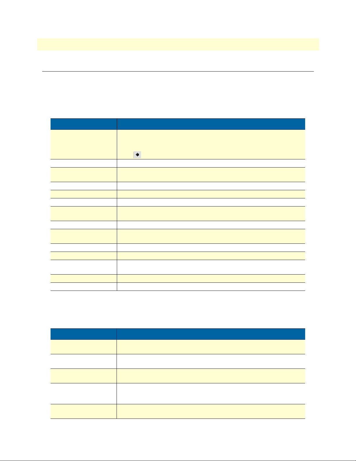
Table 1. General conventions
Convention Meaning
Garamond blue type
Futura bold type Commands and keywords are in boldface font.
Futura bold-italic type
Italicized Futura type
Futura type Indicates the names of fields or windows.
Garamond bold type Indicates the names of command buttons that execute an action.
< > Angle brackets indicate function and keyboard keys, such as <SHIFT>, <CTRL>,
[ ] Elements in square brackets are optional.
{a | b | c} Alternative but required keywords are grouped in braces ({ }) and are separated
blue screen Information you enter is in blue screen font.
screen Terminal sessions and information the system displays are in screen font.
node
SN The leading SN on a command line represents the nodename of the SmartNode
# An hash sign at the beginning of a line indicates a comment line.
Indicates a cross-reference hyperlink that points to a figure, graphic, table, or section heading. Clicking on the hyperlink jumps you to the reference. When you
have finished reviewing the reference, click on the Go to Previous View
button in the Adobe® Acrobat® Reader toolbar to return to your starting point.
Parts of commands, which are related to elements already named by the user, are
in
boldface italic
Variables for which you supply values are in
<C>, and so on.
by vertical bars ( | )
The leading IP address or nodename of a SmartNode is substituted with
boldface italic
font.
font.
italic
font
node
in
Mouse conventions
The following conventions are used when describing mouse actions:
Table 2. Mouse conventions
Convention Meaning
Left mouse button This button refers to the primary or leftmost mouse button (unless you have
changed the default configuration).
Right mouse button This button refers the secondary or rightmost mouse button (unless you have
changed the default configuration).
Point This word means to move the mouse in such a way that the tip of the pointing arrow
(referred to as the
Click Means to press and release the left or right mouse button one time quickly (as
instructed in the procedure). Make sure you do not move the cursor while clicking
a mouse button.
Double-click Means to press and release the same mouse button two times quickly. Make sure
you do not move the cursor while clicking a mouse button.
cursor
) on the screen ends up resting at the desired location.
17
Page 18

About this guide SmartNode 1000 and 2000 Series Getting Started Guide
Table 2. Mouse conventions
Convention Meaning
Drag This word means to place the cursor and then hold down the left or right mouse but-
ton (as instructed in the procedure) as you move the mouse to a new location. When
you have moved the cursor to the desired location, you can release the mouse button.
18
Page 19

Chapter 1 General Information
Chapter contents
Introduction..........................................................................................................................................................21
SmartNode 1200 description.................................................................................................................................22
Front panel .....................................................................................................................................................22
Rear panel .......................................................................................................................................................23
Clock mode configuration (Model SN1200) ...................................................................................................25
SmartNode 1400 description.................................................................................................................................25
Front panel .....................................................................................................................................................25
Rear panel .......................................................................................................................................................26
Clock mode configuration (Model SN1400) ...................................................................................................27
SmartNode 2300 description.................................................................................................................................28
Front panel .....................................................................................................................................................29
Rear panel .......................................................................................................................................................29
Expansion slots ..........................................................................................................................................30
On-board ports .........................................................................................................................................30
SmartNode 2400 description.................................................................................................................................32
Front panel .....................................................................................................................................................32
Rear panel .......................................................................................................................................................33
Expansion slots ..........................................................................................................................................33
On-board ports .........................................................................................................................................33
Interface cards descriptions....................................................................................................................................35
IC-4FXS Gateway interface card for 4 analog FXS ports .................................................................................35
Front panel ...............................................................................................................................................35
Ports ..........................................................................................................................................................36
Description ...............................................................................................................................................36
IC-4BRV 8-channel gateway interface card for ISDN BRI ..............................................................................37
Front panel ...............................................................................................................................................37
Ports ..........................................................................................................................................................37
Description ...............................................................................................................................................38
Operating modes .......................................................................................................................................38
Hardware bypass .......................................................................................................................................38
Network integration ..................................................................................................................................39
S-Bus line power .......................................................................................................................................41
Line power jumper settings .......................................................................................................................41
Jumper settings for IC-4BRV and PM-48V-INT (or PM-40V-INT) .................................................. 42
IC-4BRV-8V 8-channel gateway interface card for ISDN BRI ........................................................................43
Front panel ...............................................................................................................................................44
Ports ..........................................................................................................................................................44
Description ...............................................................................................................................................44
Operating modes .......................................................................................................................................45
19
Page 20

1 • General Information SmartNode 1000 and 2000 Series Getting Started Guide
S-Bus line power .......................................................................................................................................45
Line power jumper settings .......................................................................................................................45
Jumper settings for IC-4BRV-8V ........................................................................................................ 46
IC-4BRV-8VR—8-channel gateway interface card for ISDN BRI with hardware bypass (emergency) relay ....46
IC-E1V 30-channel E1 gateway interface card for ISDN PRI .........................................................................47
Front panel ...............................................................................................................................................47
Interface ....................................................................................................................................................47
Description ...............................................................................................................................................47
Interface modes .........................................................................................................................................48
IC-E1V-0 E1 gateway interface card for ISDN PRI (circuit switching only) ...................................................48
IC-E1V-15 15-channel E1 gateway interface card for ISDN PRI ....................................................................48
IC-T1V 23-channel T1 gateway interface card for ISDN PRI ........................................................................48
Front panel ...............................................................................................................................................49
Interface ....................................................................................................................................................49
Description ...............................................................................................................................................49
Interface modes .........................................................................................................................................50
IC-T1V-0 T1 gateway interface card for ISDN PRI (circuit switching only) ...................................................50
IC-T1V-15 15-channel T1 gateway interface card for ISDN PRI ...................................................................50
20
Page 21
SmartNode 1000 and 2000 Series Getting Started Guide 1 • General Information
Introduction
This guide describes installing the SmartNode 1000 Series and 2000 Series devices.
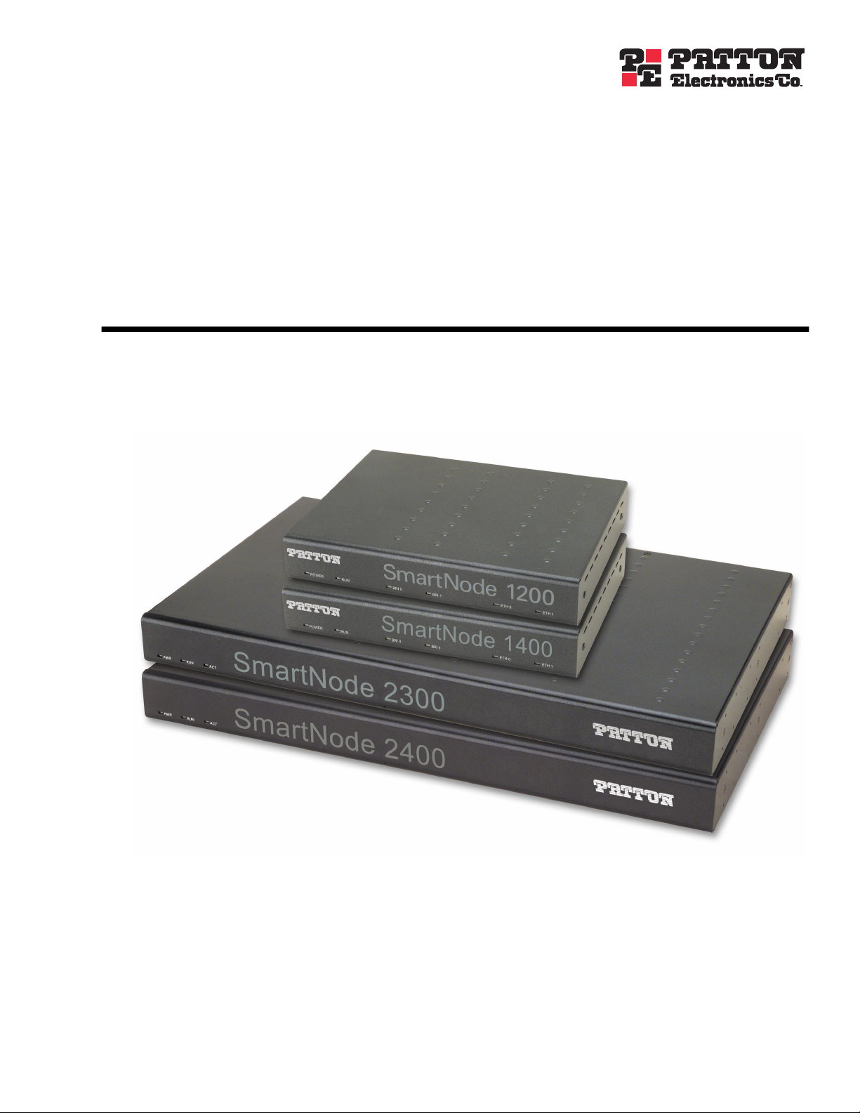
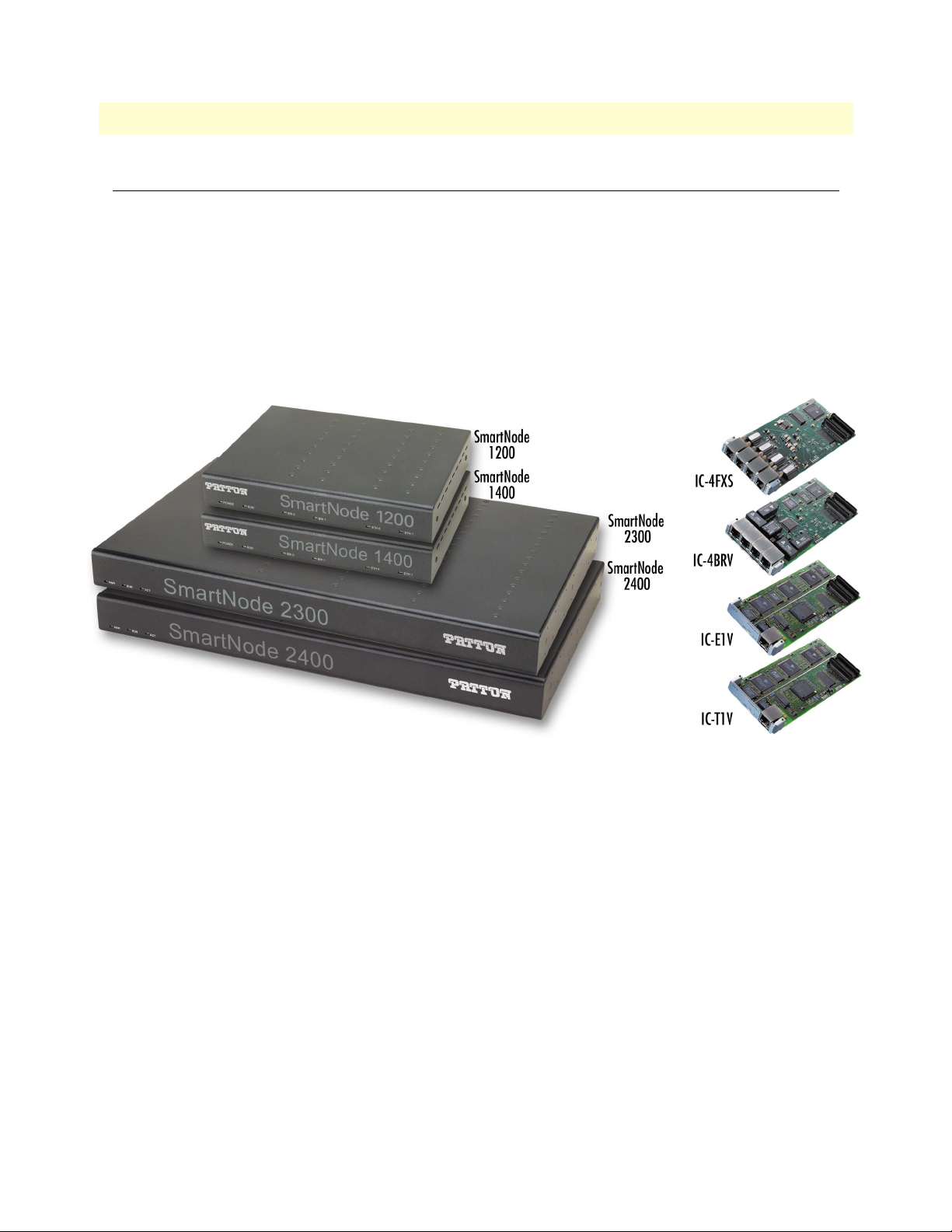
The SmartNode 1000 series are compact IP access devices for applications in SOHO or branch office environments. Two models are currently available with 2 or 4 voice over IP channels (see figure 1):
• SmartNode 1200—Dual Ethernet router, 2-channel ISDN BRI gateway (see “SmartNode 1200 descrip-
tion” on page 22)
• SmartNode 1400—Dual Ethernet router, 4-channel ISDN BRI gateway (see “SmartNode 1400 descrip-
tion” on page 25)
Figure 1. SmartNode 1000 Series and 2000 Series VoIP media gateways, and interface cards
The SmartNode 2000 Series are modular IP network nodes designed for medium and large enterprise applications.
The 2000 series features expansion slots for a range of interface cards. Currently available models are (see figure 1):
• SmartNode 2300—Serial/Ethernet router with three expansion slots for interface cards (see “SmartNode
2300 description” on page 28)
• SmartNode 2400—High performance router with four expansion slots for interface cards (see “SmartNode
2400 description” on page 32)
The following interface cards (see figure 1) are available for use with the SmartNode 2000 Series devices (see
“Interface cards descriptions” on page 35):
• IC-4FXS—Gateway interface card for 4 analog FXS ports
• IC-4BRV—8-channel gateway interface card for ISDN BRI
• IC-E1V—30-channel E1 gateway interface card for ISDN PRI
• IC-T1V—23-channel T1 gateway interface card for ISDN PRI
Introduction 21
Page 22
1 • General Information SmartNode 1000 and 2000 Series Getting Started Guide
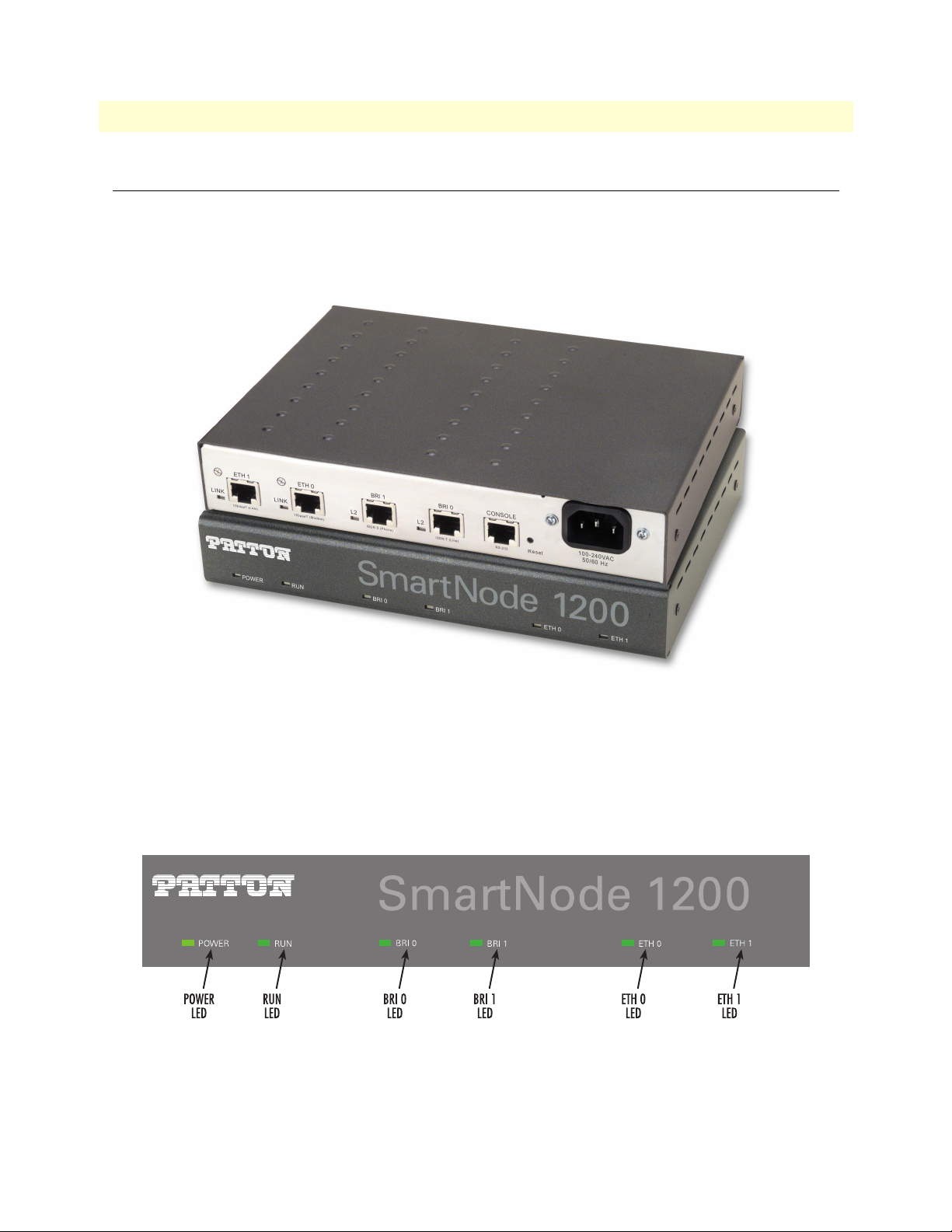
SmartNode 1200 description
The SmartNode Model 1200 (see figure 2) is a compact voice/data access device that supports two voice channels. The user interfaces consist of one ISDN BRI port and one Ethernet 10Base-T port. Network access comprises one ISDN BRI port and one Ethernet 10Base-T port. It is suitable for home office or small office
applications. The ventilated metal case can be placed on a desktop or be wall-mounted.
Figure 2. Model 1200 (front and rear views shown)
Front panel
The Model 1200 front panel (see figure 3) includes the following LEDs for at-a-glance status display:
• POWER and RUN LEDs that indicate the device status.
• BRI0, BRI1, ETH0, and ETH1 LEDs that indicate the status of the interfaces.
Figure 3. SmartNode 1200 front panel
See chapter 11, “Monitoring Status” on page 151, for more information on LED indications.
22 SmartNode 1200 description
Page 23
SmartNode 1000 and 2000 Series Getting Started Guide 1 • General Information
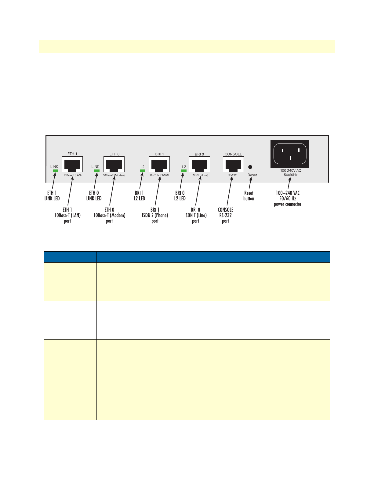
Rear panel
The SmartNode 1200 rear panel includes the following LEDs for at-a-glance status display (see figure 4):
• LINK LEDs that indicate the status of the Ethernet connections
• L2 LEDs that show the status of the BRI interfaces
The ports are described in table 3 (see appendix B, “Cabling” on page 165 for connection cable and appendix
C, “Port pin-outs” on page 177 for pin-out data).
Port Description
ETH 0
10Base-T (Modem)
ETH 1
10Base-T (LAN)
BRI 0
ISDN T (Line)
Figure 4. SmartNode 1200 rear panel
Table 3. SmartNode 1200 port description
10Base-T Ethernet RJ-45 socket that connects the SmartNode with an Ethernet device
(usually a transmission modem, i.e. cable or DSL modem).
ing on the pin out of the modem, it can be connected with a straight-through wired
cable or a cross-over cable. The
is connected correctly to an active Ethernet device.
10Base-T Ethernet RJ-45 socket that connects the SmartNode with an Ethernet device,
usually a LAN hub or switch.
through wired cable to a hub or a cross-over cable to a host (PC) port. The
the left of the connector is lit when the port is connected correctly to an active Ethernet
device.
ISDN BRI RJ-45 socket that connects the SmartNode with an ISDN network termination
(NT). The interface may be used as a fallback port. The L2 LED to the left of the connector
is lit when the port is connected correctly to an active ISDN device (Layer 1 is up). The
interface is internally terminated at 100 ohm. It may be powered by an external power
supply to feed TEs connected to BRI 1. Refer to appendix B,
connection details.
Note External S-Bus power supplies must comply with the voltage and cur-
rent limits set by ISDN standards, i.e. max. 40 VDC and 200 mA.
LINK
LED to the left of the connector is lit when the port
ETH 1
is a host port; it can be connected with a straight-
ETH 0
is a host port; depend-
LINK
LED to
“Cabling” on page 165 for
Note The L2 LED indication depends on the connected device.
SmartNode 1200 description 23
Page 24
1 • General Information SmartNode 1000 and 2000 Series Getting Started Guide
Table 3. SmartNode 1200 port description (Continued)
Port Description
BRI 1
ISDN S (Phone)
Console
(RS-232)
ISDN BRI RJ-45 socket that connects the SmartNode with an ISDN S-Bus, e.g. a PBX.
The L2 LED to the left of the connector is lit when the port is connected correctly to an
active ISDN device (Layer 1 is up). The interface is internally terminated at 100 ohm.
Note The L2 LED indication depends on the connected device.
RS-232 RJ-45 connector that connects the SmartNode with a serial terminal such as a
PC or workstation with an RS-232 interface, with the following settings:
• 9600 bps, no parity, 8 bit, 1 stop bit, 1 start bit
• The console port is only used for service and maintenance
Do not plug in an ISDN connection. The voltage on the S-Bus
may permanently damage the console interface.
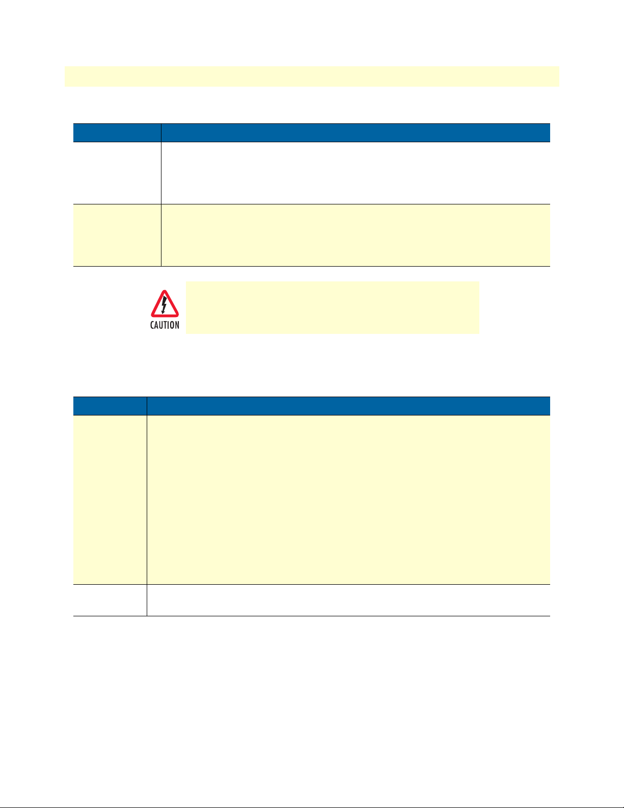
In addition, two other elements—the Reset button and power input socket—are available on the rear panel of a
SmartNode 1200 as described in table 4.
Table 4. SmartNode 1200 Reset button and power line socket on rear panel
Element Description
Reset button The button has three different functions:
• Manual Restart—During normal operation, pressing and releasing the reset button
will cause a system reboot. The application will be restarted without any change to the
existing SmartWare configuration.
• Restoration—Pressing and holding the reset button for 5 seconds will restore the fac-
tory configuration and automatically reboot the system.
Note In this case the existing IP SmartWare configuration is lost.
• Boot loader—Powering the SmartNode while pressing the reset button for 5 seconds
will cause the factory-fitted boot loader to start in place of the application. The boot
loader uses a minimal set of parameters. In case the application does not start correctly,
the boot loader can be used as a fallback to download a new software version.
100–240 VAC
50/60 Hz
Electricity supply socket for mains power cable.
24 SmartNode 1200 description
Page 25
SmartNode 1000 and 2000 Series Getting Started Guide 1 • General Information
Clock mode configuration (Model SN1200)
The following table shows which clock mode configurations are allowed for the SmartNode 1200 and which
port is used as the clock source.
Table 5. Clock-modes and clock-sources for the SmartNode 1200
Port 0
Clock Mode
Slave (User) Master (Net) Port 0. This is the only configuration that is supported on the SmartNode
Master (Net) Slave (User) Not supported
Port 1
Clock Mode
Clock Source
1200.
Clock is taken from port 0 if available. Otherwise it is generated internally.
SmartNode 1400 description
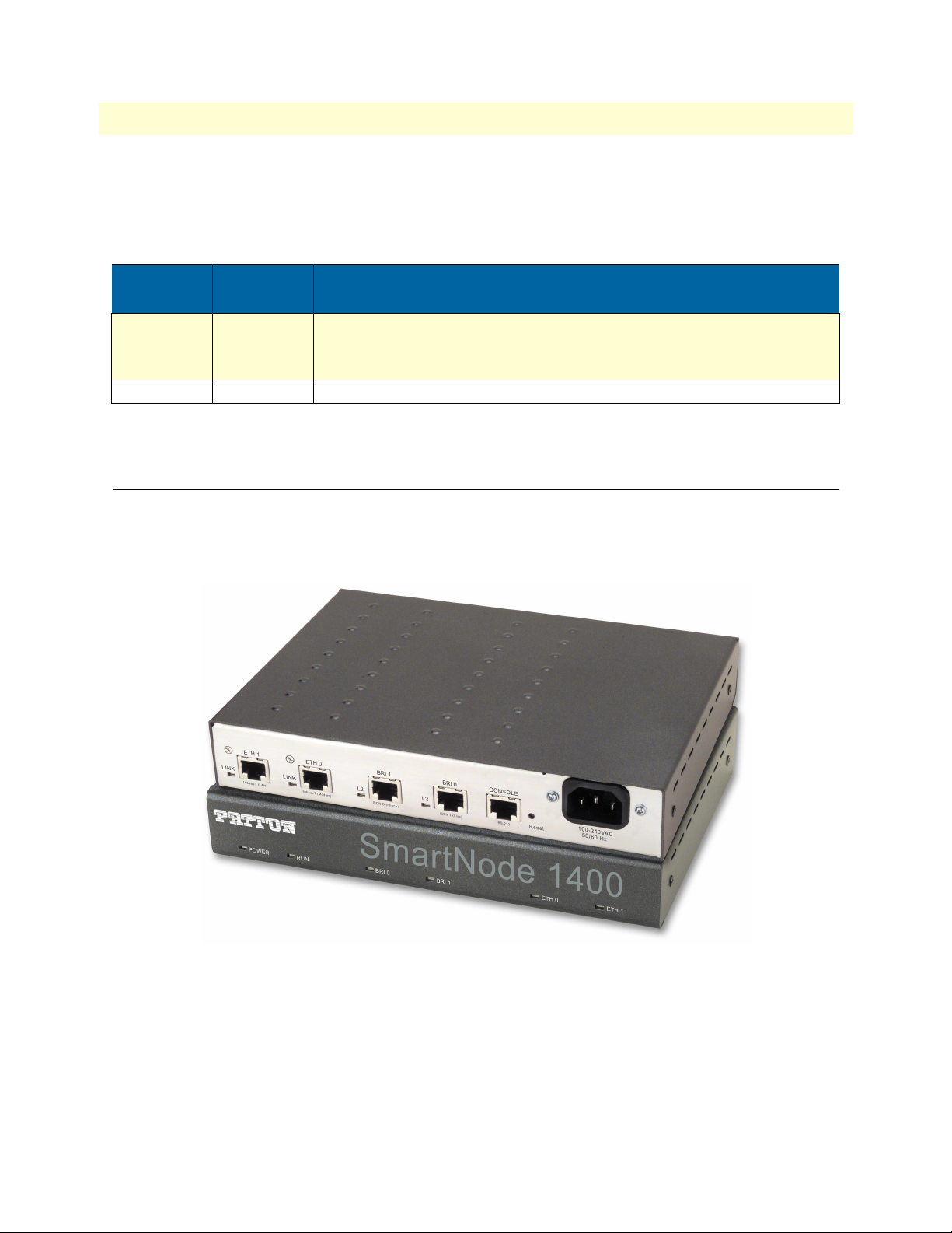
The SmartNode Model 1400 (see figure 5) is a compact voice/data access device that supports four voice channels.
The interfaces consist of two ISDN BRI ports and two Ethernet 10Base-T ports. It is suitable for enterprise networking and small office environments. The ventilated metal case can be wall-mounted or placed on a desktop.
Figure 5. Model 1400 (front and rear views shown)
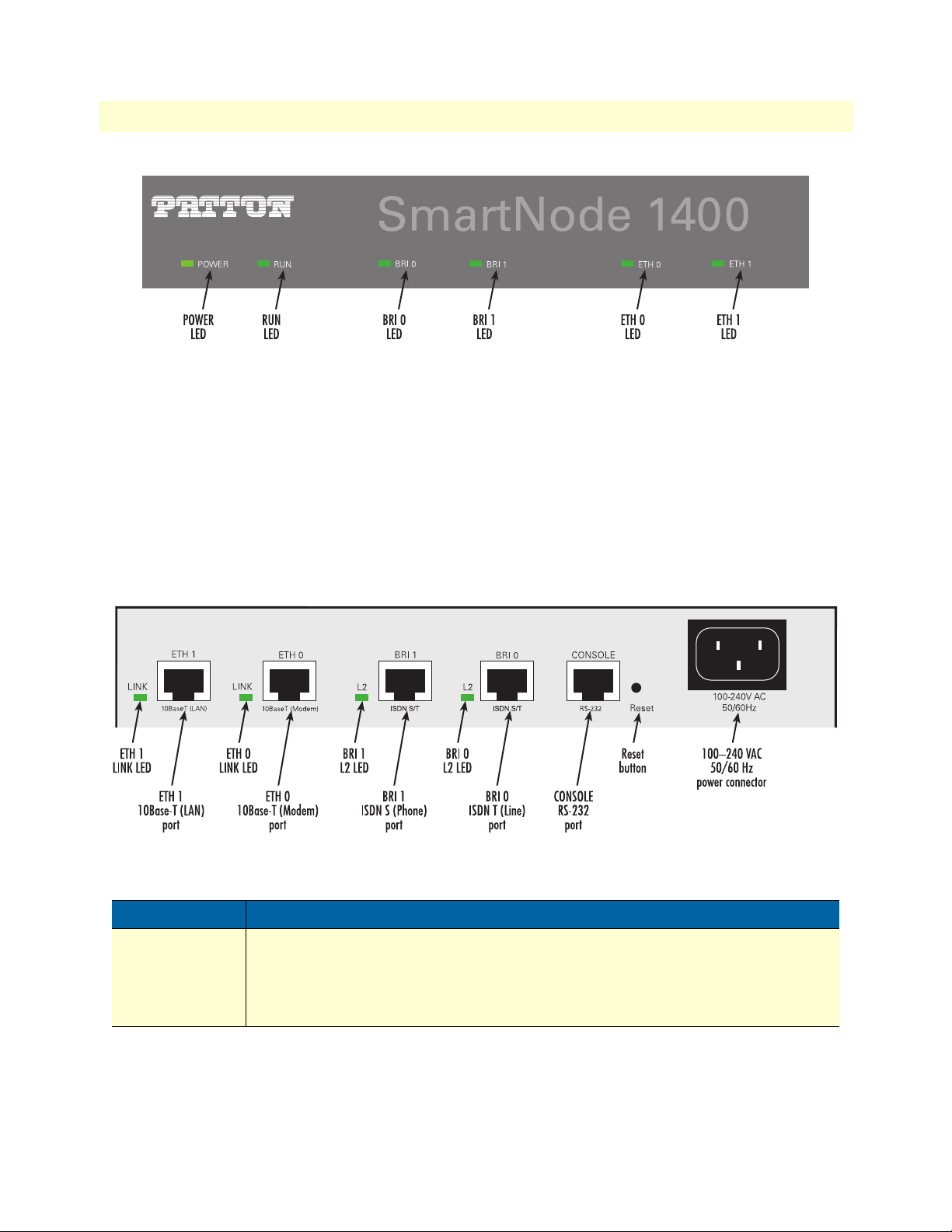
Front panel
The Model 1400 front panel (see figure 7) includes the following LEDs for at-a-glance status display:
• POWER and RUN LEDs that indicate the device status
• BRI0, BRI1, ETH0, and ETH1 LEDs that indicate the status of the interfaces
SmartNode 1400 description 25
Page 26
1 • General Information SmartNode 1000 and 2000 Series Getting Started Guide
Figure 6. SmartNode 1400 front panel
See chapter 11, “Monitoring Status” on page 151 for more information on LED indications.
Rear panel
The SmartNode 1400 rear panel includes the following LEDs for at-a-glance status display (see figure 4):
• LINK LEDs that indicate the status of the Ethernet connections
• L2 LEDs that show the status of the BRI interfaces
The ports are described in table 6 (see appendix B, “Cabling” on page 165 for connection cable and appendix
C, “Port pin-outs” on page 177 for pin-out data).
Figure 7. SmartNode 1400 rear panel
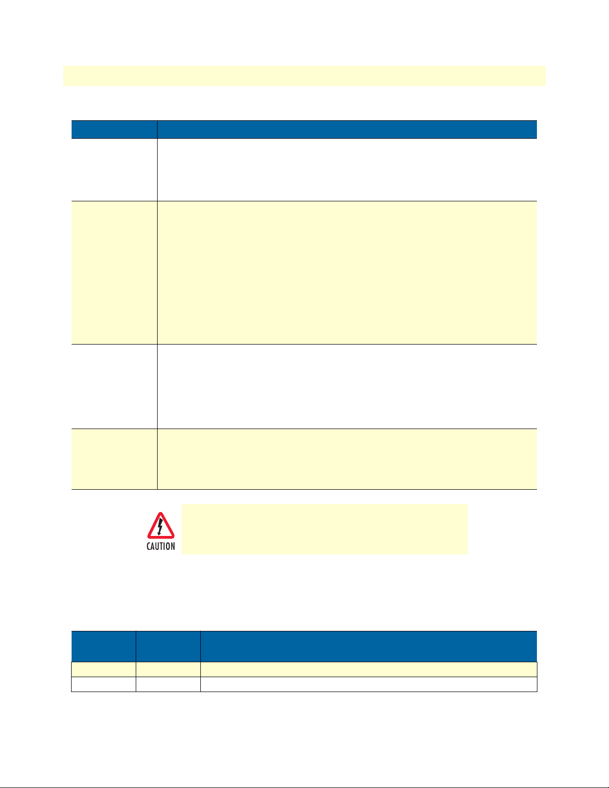
Table 6. SmartNode 1400 port description
Port Description
ETH 0
10Base-T (Modem)
26 SmartNode 1400 description
10Base-T Ethernet RJ-45 socket that connects the SmartNode with an Ethernet device
(usually a transmission modem, i.e. cable or DSL modem).
ing on the pin out of the modem, it can be connected with a straight-through wired
cable or a cross-over cable. The
is connected correctly to an active Ethernet device.
LINK
LED to the left of the connector is lit when the port
ETH 0
is a host port; depend-
Page 27
SmartNode 1000 and 2000 Series Getting Started Guide 1 • General Information
Table 6. SmartNode 1400 port description (Continued)
Port Description
ETH 1
10Base-T (LAN)
BRI 0
ISDN S/T
BRI 1
ISDN S/T
10Base-T Ethernet RJ-45 socket that connects the SmartNode with an Ethernet device,
usually a LAN hub or switch.
through wired cable to a hub or a cross-over cable to a host (PC) port. The
the left of the connector is lit when the port is connected correctly to an active Ethernet
device.
ISDN BRI RJ-45 socket that connects the SmartNode with an ISDN device over an S/T
bus, e.g. a PBX or an NT. The interface may be used as fallback if connected to an NT.
The L2 LED to the left of the connector is lit when the port is connected correctly to an
active ISDN device (Layer 1 is up). The pin-out is configurable; see the document SmartWare Software Configuration Guide. The interface is internally terminated at 100 ohm.
It may be powered by an external power supply to feed TEs connected to BRI 1. Refer to
appendix B,
Note External S-Bus power supplies must comply with the voltage and cur-
Note The L2 LED indication depends on the connected device.
ISDN BRI RJ-45 socket that connects the SmartNode with an ISDN device over an S/T
bus, such as a PBX. The L2 LED to the left of the connector is lit when the port is connected correctly to an active ISDN device (Layer 1 is up). The pin out is configurable;
see the document
terminated at 100 ohm.
“Cabling” on page 165 for connection details.
rent limits set by ISDN standards, i.e. max. 40 VDC and 200 mA.
SmartWare Software Configuration Guide
ETH 1
is a host port; it can be connected with a straight-
. The interface is internally
LINK
LED to
Note The L2 LED indication depends on the connected device.
Console
(RS-232)
RS-232 RJ-45 connector that connects the SmartNode with a serial terminal such as a
PC or workstation with a RS-232 interface, with the following settings:
• 9600 bps, no parity, 8 bit, 1 stop bit, 1 start bit
• The console port is only used for service and maintenance
Do not plug in an ISDN connection. The voltage on the S-Bus
may permanently damage the console interface.
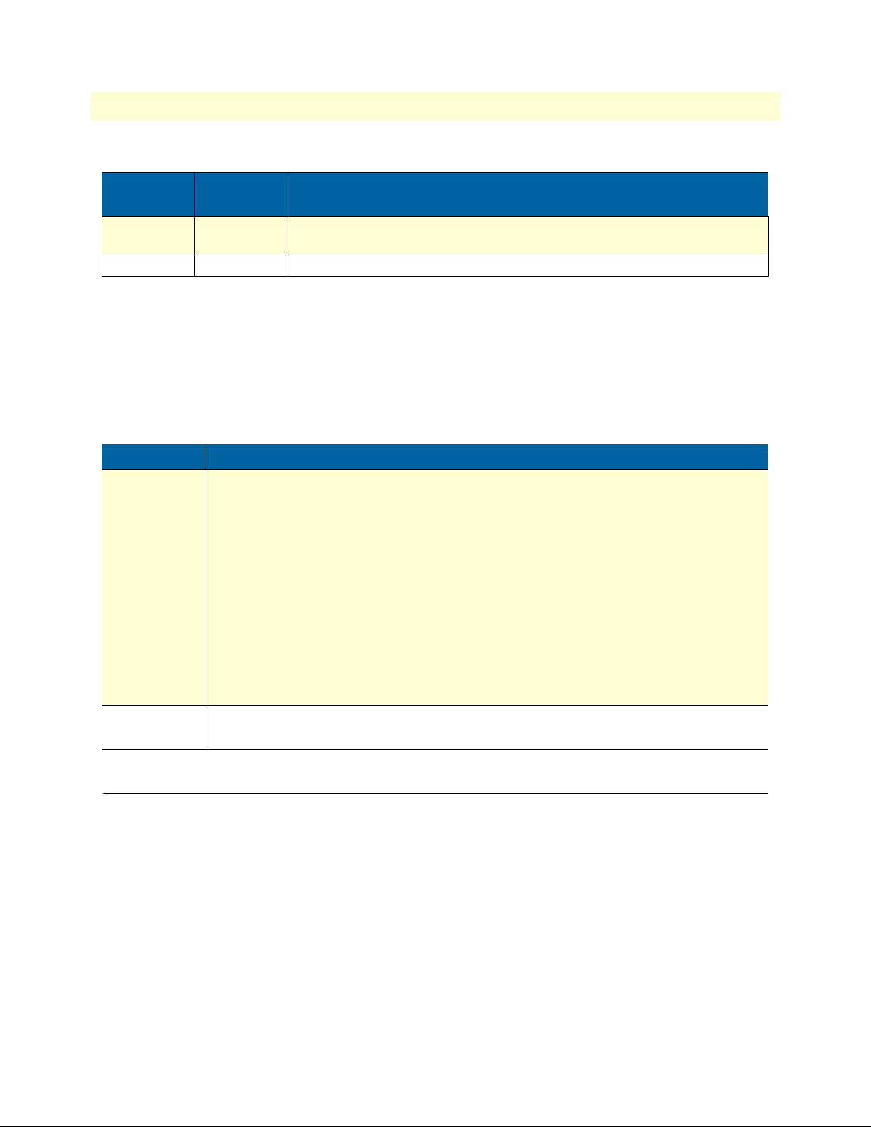
Clock mode configuration (Model SN1400)
The following table shows which clock mode configurations are allowed for the SmartNode 1400 and which
port is used as the clock source.
Table 7. Clock-modes and clock-sources for the SmartNode 1400
Port 0
Clock Mode
Slave (User) Slave (User) Port 1
Master (Net) Master (Net) Clock generated internally
Port 1
Clock Mode
Clock Source
SmartNode 1400 description 27
Page 28
1 • General Information SmartNode 1000 and 2000 Series Getting Started Guide
Table 7. Clock-modes and clock-sources for the SmartNode 1400
Port 0
Clock Mode
Slave (User) Master (Net) Port 0. Clock is taken from port 0 if available. Otherwise it is generated inter-
Master (Net) Slave (User) Not supported
Port 1
Clock Mode
nally.
Note The SmartNode 1400 needs to be rebooted twice after changing the
Clock Source
clock mode.
In addition, two other elements—the Reset button and power input socket—are available on the rear panel of a
SmartNode 1200 as described in table 8.
Table 8. SmartNode 1200 Reset button and power line socket on rear panel
Element Description
Reset button The button has three different functions:
• Manual Restart—During normal operation pressing and releasing the reset button
will cause a system reboot. The application will be restarted without any change to the
existing SmartWare configuration.
• Restoration—Pressing and holding the reset button for 5 seconds will restore the fac-
tory configuration and automatically reboot the system.
Note In this case the existing IP SmartWare configuration is lost.
• Boot loader—Powering the SmartNode while pressing the reset button for 5 seconds
will cause the factory-fitted boot loader to start in place of the application. The boot
loader uses a minimal set of parameters. In case the application does not start correctly,
the boot loader can be used as a fallback to download a new software version.
100–240 VAC
50/60 Hz
Electricity supply socket for mains power cable.
SmartNode 2300 description
The SmartNode Model 2300 (see figure 8) is a powerful multi-service access device. The 19-in. aluminum
chassis can be rack-mounted and it provides three expansion slots for interface cards.
Note If you will be mounting the SmartNode 2300 in a 19-in. rack, see
section “Mounting the SmartNode 2300” on page 93 for details.
28 SmartNode 2300 description
Page 29
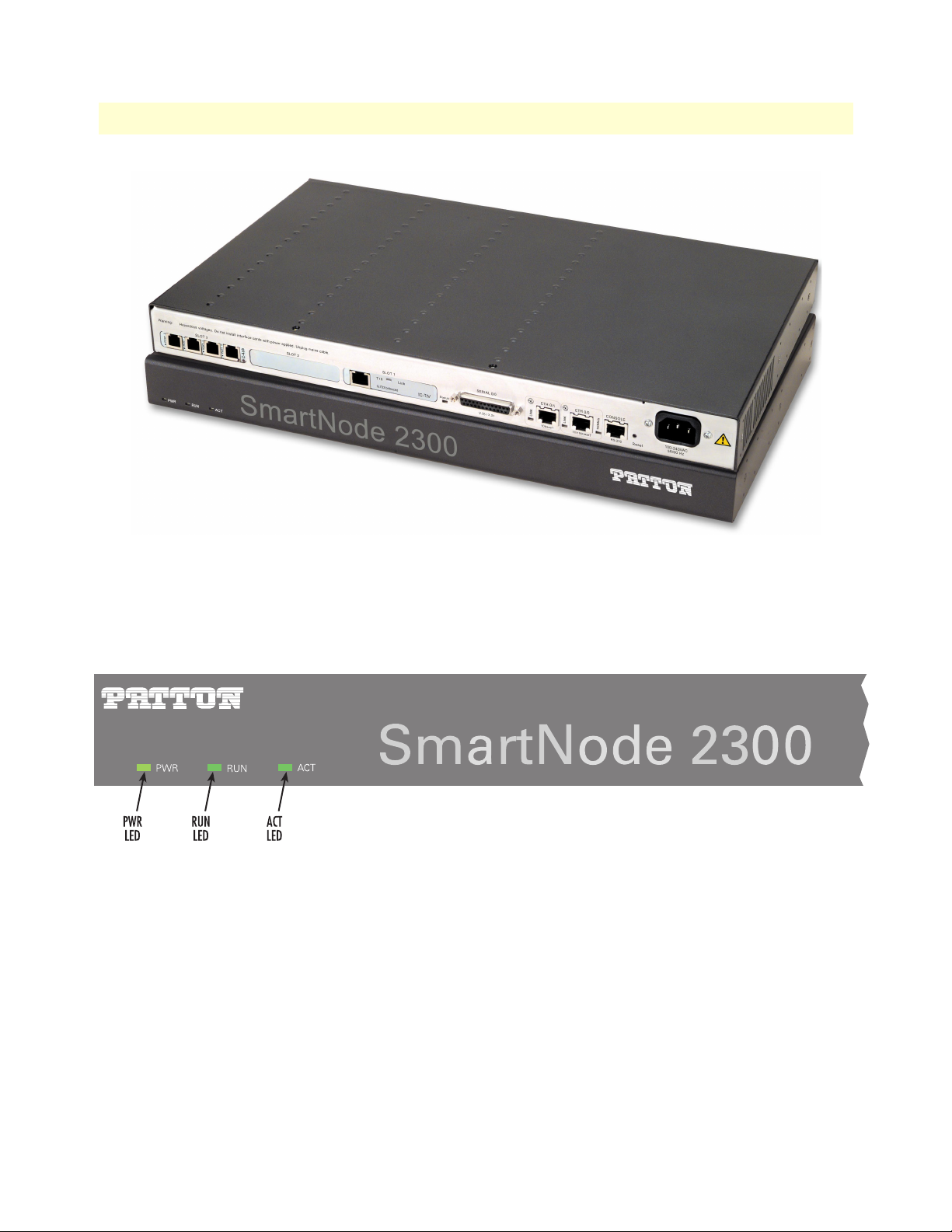
SmartNode 1000 and 2000 Series Getting Started Guide 1 • General Information
Figure 8. Model 2300 (front and rear views shown)
Front panel
The SmartNode 2300 rear panel includes the PWR, RUN, and ACT LEDs that indicate the status of the device
(see figure 9). See chapter 11, “Monitoring Status” on page 151 for detailed information on the LED states.
Figure 9. SmartNode 2300 front panel
See chapter 11, “Monitoring Status” on page 151 for more information on LED indications.
Rear panel
The SmartNode 2300 rear panel is depicted in figure 10. There are three expansion slots for optional interface
cards, and four board-mounted sockets. The Status, LINK, and 100Mb/s LEDs indicate the status of the on-
SmartNode 2300 description 29
Page 30
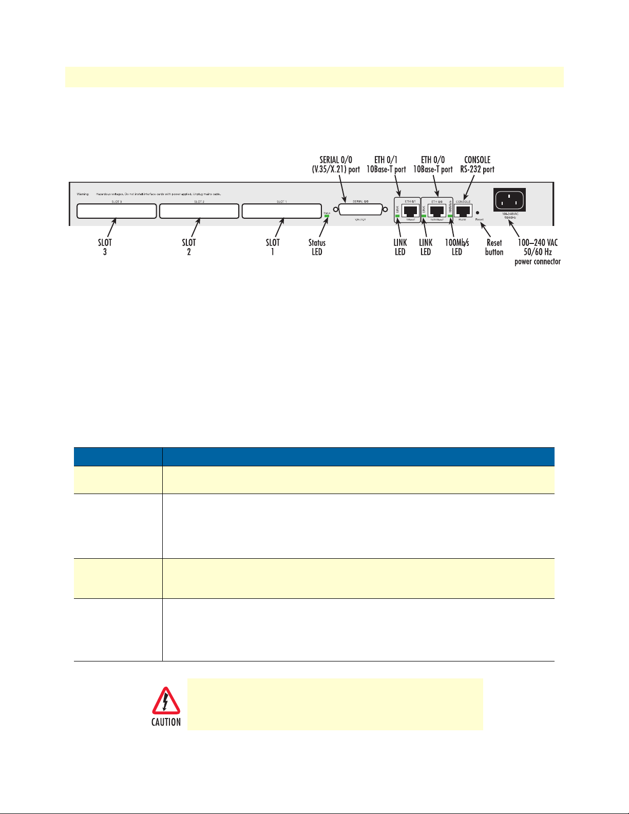
1 • General Information SmartNode 1000 and 2000 Series Getting Started Guide
board interfaces (see appendix B, “Cabling” on page 165 for connection cable and appendix C, “Port pin-outs”
on page 177 for pin-out data).
Figure 10. SmartNode 2300 rear panel
Expansion slots
The slots labeled SLOT 1, SLOT 2, and SLOT 3 (see figure 10) accept different PMC interface cards to integrate voice and data over IP networks (see “Interface cards descriptions” on page 35 for more information).
On-board ports
Three motherboard-mounted network interfaces are available for use, independent of those that may be
included with interface cards mounted in SLOT 1, SLOT 2, or SLOT 3. The motherboard-mounted ports are
described in table 9 (see appendix B, “Cabling” on page 165 for connection cable and appendix C, “Port pin-
outs” on page 177 for pin-out data).
Port Description
SERIAL 0/0
(V.35 / X.21)
ETH 0/1
(10BaseT)
ETH 0/0
(10/100BaseT)
Console
(RS-232)
Table 9. SmartNode 2300 port description
DB-25 socket providing a V.35 and X.21 interface for leased-lines at up to 2 Mbps. The
LINK
LED to the left of the connector indicates its status.
10Base-T Ethernet RJ-45 socket that connects the SmartNode with an Ethernet device,
such as a wide area transmission modem, Ethernet hub, or switch.
port; it can be connected with a straight-through wired cable to a hub, or a cross-over
cable to a host port. The
Ethernet device.
10/100Base-T Ethernet RJ-45 socket. The interface is similar in function to ETH 0/1
except that it also supports 100Base-T. The
nected correctly to an active 100Base-T Ethernet device.
RS-232 RJ-45 connector that connects the SmartNode with a serial terminal such as a
PC or workstation with a RS-232 interface, with the following settings:
LINK
LED is lit when the port is connected correctly to an active
100Mb/s
LED is lit when the port is con-
ETH 0/1
is a host
• 9600 bps, no parity, 8 bit, 1 stop bit, 1 start bit
• The console port is only used for service and maintenance
Do not plug in an ISDN connection. The voltage on the S-Bus
may permanently damage the console interface.
30 SmartNode 2300 description
Page 31

SmartNode 1000 and 2000 Series Getting Started Guide 1 • General Information
In addition, two other elements the—Reset button and power input socket—are available on the rear panel of a
SmartNode 1200 as described in table 10.
Table 10. SmartNode 2300 Reset button and power line socket on rear panel
Element Description
Reset button The button has three different functions:
• Manual Restart—During normal operation pressing and releasing the reset button
will cause a system reboot. The application will be restarted without any change to the
existing SmartWare configuration.
• Restoration—Pressing and holding the reset button for 5 seconds will restore the fac-
tory configuration and automatically reboot the system.
Note In this case the existing IP SmartWare configuration is lost.
• Boot loader—Powering the SmartNode while pressing the reset button for 5 seconds
will cause the factory-fitted boot loader to start in place of the application. The boot
loader uses a minimal set of parameters. In case the application does not start correctly,
the boot loader can be used as a fallback to download a new software version.
100–240 VAC
50/60 Hz
Electricity supply socket for mains power cable.
SmartNode 2300 description 31
Page 32

1 • General Information SmartNode 1000 and 2000 Series Getting Started Guide
SmartNode 2400 description
The SmartNode Model 2400 (see figure 11) is a powerful multi-service access device. The 19-in. aluminum
chassis can be rack-mounted, and provides three expansion slots for interface cards.
Note If you will be mounting the SmartNode 2400 in a 19-in. rack, see
section “Mounting the SmartNode 2400” on page 111 for details.
Figure 11. Model 2400 (front and rear views shown)
Front panel
The SmartNode 2400 rear panel includes the PWR, RUN, and ACT LEDs that indicate the status of the device
(see figure 12). See chapter 11, “Monitoring Status” on page 151 for detailed information on the LED states.
Figure 12. SmartNode 2400 front panel
See chapter 11, “Monitoring Status” on page 151 for more information on LED indications.
32 SmartNode 2400 description
Page 33
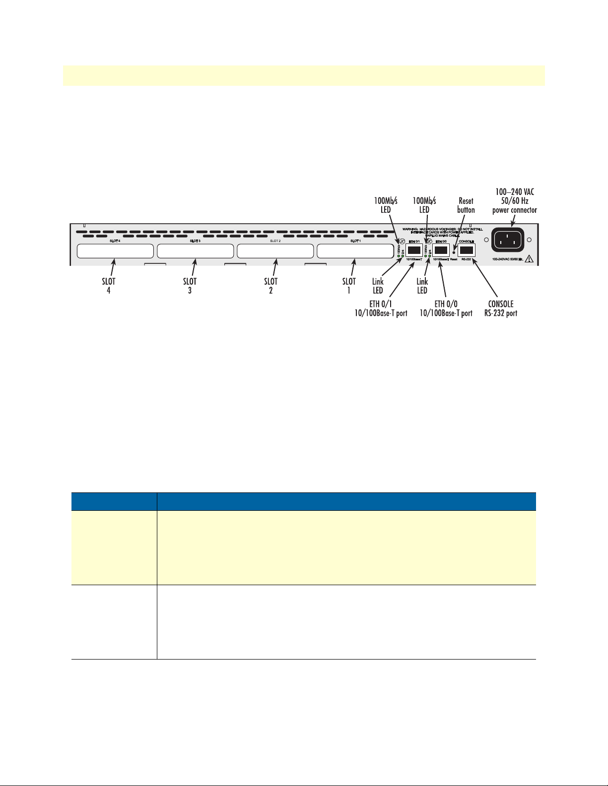
SmartNode 1000 and 2000 Series Getting Started Guide 1 • General Information
Rear panel
The SmartNode 2400 rear panel is depicted in figure 13. There are four expansion slots for optional interface
cards, and four board-mounted sockets. There are four expansion slots for optional interface cards, and four
board-mounted sockets. The Link, and 100Mb/s LEDs indicate the status of the Ethernet ports. See appendix
B, “Cabling” on page 165 for connection cable and appendix C, “Port pin-outs” on page 177 for pin-out data.
Figure 13. SmartNode 2400 rear panel
Expansion slots
The slots labeled SLOT 1, SLOT 2, SLOT 3 and SLOT 4 (see figure 13) accept different PMC interface cards to
integrate voice and data over IP networks (see “Interface cards descriptions” on page 35 for more information).
On-board ports
Three motherboard-mounted network interfaces are available for use, independent of those that may be
included with interface cards mounted in SLOT 1, SLOT 2, SLOT 3, or SLOT 4. The motherboard-mounted
ports are described in table 11 (see appendix B, “Cabling” on page 165 for connection cable and appendix C,
“Port pin-outs” on page 177 for pin-out data).
Table 11. SmartNode 2400 port description
Port Description
ETH 0/1
(10/100BaseT)
ETH 0/0
(10/100BaseT)
Ethernet RJ-45 socket that connects the SmartNode with an Ethernet device, such as a
wide area transmission modem, Ethernet hub, or switch.
be connected with a straight-through wired cable to a hub, or a cross-over cable to a
host port. The
device. The
100Base-T Ethernet device.
Ethernet RJ-45 socket that connects the SmartNode with an Ethernet device, such as a
wide area transmission modem, Ethernet hub, or switch.
be connected with a straight-through wired cable to a hub, or a cross-over cable to a
host port. The
device. The
100Base-T Ethernet device.
Link
LED is lit when the port is connected correctly to an active Ethernet
100Mb/s
Link
100Mb/s
LED is lit when the port is connected correctly to an active
LED is lit when the port is connected correctly to an active Ethernet
LED is lit when the port is connected correctly to an active
ETH 0/1
ETH 0/0
is a host port; it can
is a host port; it can
SmartNode 2400 description 33
Page 34
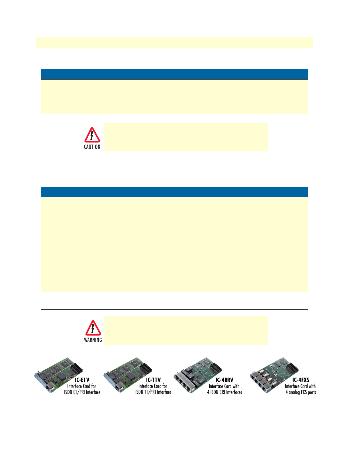
1 • General Information SmartNode 1000 and 2000 Series Getting Started Guide
Table 11. SmartNode 2400 port description (Continued)
Port Description
Console
(RS-232)
RS-232 RJ-45 connector that connects the SmartNode with a serial terminal such as a
PC or workstation with a RS-232 interface, with the following settings:
• 9600 bps, no parity, 8 bit, 1 stop bit, 1 start bit
• The console port is only used for service and maintenance
Do not plug in an ISDN connection. The voltage on the S-Bus
may permanently damage the console interface.
In addition, two other elements—the Reset button and power input socket—are available on the rear panel of a
SmartNode 2400 as described in table 12.
Table 12. SmartNode 2400 Reset button and power line socket on rear panel
Element Description
Reset button The button has three different functions:
• Manual Restart—During normal operation pressing and releasing the reset button
will cause a system reboot. The application will be restarted without any change to the
existing SmartWare configuration.
• Restoration—Pressing and holding the reset button for 5 seconds will restore the fac-
tory configuration and automatically reboot the system.
100–240 VAC
50/60 Hz
Note In this case the existing IP SmartWare configuration is lost.
• Boot loader—Powering the SmartNode while pressing the reset button for 5 seconds
will cause the factory-fitted boot loader to start in place of the application. The boot
loader uses a minimal set of parameters. In case the application does not start correctly,
the boot loader can be used as a fallback to download a new software version.
Electricity supply socket for mains power cable.
The mains supply
with a maximum tripping current of 16A.
Figure 14. SmartNode PMC interface cards
must
be secured with an external fuse or circuit-breaker,
34 SmartNode 2400 description
Page 35

SmartNode 1000 and 2000 Series Getting Started Guide 1 • General Information
Interface cards descriptions
The following interface cards (see figure 14) are available for use with the SmartNode 2000 Series devices:
• IC-4FXS—Gateway interface card for 4 analog FXS ports (see page 35)
• IC-4BRV—8-channel gateway interface card for ISDN BRI (see page 37)
• IC-4BRV-8V—8-channel gateway interface card for ISDN BRI (see page 43)
• IC-4BRV-8VR—8-channel gateway interface card for ISDN BRI with hardware bypass (emergency) relay
(see page 46)
• IC-E1V—30-channel E1 gateway interface card for ISDN PRI (see page 47)
• IC-E1V-0—E1 Gateway interface card for ISDN PRI (circuit switching only) (see page 48)
• IC-E1V-15—15-channel E1 gateway interface card for ISDN PRI (see page 48)
• IC-T1V—23-channel T1 gateway interface card for ISDN PRI (see page 48)
• IC-T1V-0—T1 gateway interface card for ISDN PRI - circuit switching only (see page 50)
• IC-T1V-15—15-channel T1 gateway interface card for ISDN PRI (see page 50)
IC-4FXS Gateway interface card for 4 analog FXS ports
The IC-4FXS is a PMC standard compatible interface card for the SmartNode 2000 series. It provides 4 analog FXS ports and connects to the SmartNode base unit through a PCI packet and PCM circuit interface.
The IC-4FXS supports up to 4 simultaneous voice or fax calls. It is a flexible analog telephony card designed to
meet the needs of small enterprises that want to connect their analog telephony equipment, such as an analog
PBX or analog telephones, to a multi-service IP network.
The on-board dedicated micro-controller and DSPs off-load the CPU of the SmartNode 2000 series base unit
enabling the conversion of voice/fax circuits into related IP-packets in real-time with minimal delay and jitter.
Front panel
The front view of the IC-4FXS interface card is depicted in figure 15. The individual sockets are labeled on the bezel.
Interface cards descriptions 35
Page 36

1 • General Information SmartNode 1000 and 2000 Series Getting Started Guide
Figure 15. IC-4FXS
Ports
The card provides the four FXS ports whose details are tabulated in table 13. Protector circuits protect the
ports from high voltage surges. See appendix A, “Specifications” on page 159 for pin out data.
Table 13. IC-4FXS port description
Port Description
0 ... 3 FXS RJ-11 socket to connect the SmartNode to an analog terminal (subscriber). Only two wires
(Ring, Tip) are used. The ‘Loop Start’ method is used to signal whether the terminal is on- or off-hook
(loop closed = on-hook).
Description
The IC-4FXS interface card provides four FXS ports, together allowing up to 4 analog voice channels to work
in parallel.
Each ports provides the following the following:
• -48 VDC to the connected terminal
• Ring voltage to the connected terminal (normally 96 VAC at 25 Hz)
• On-hook transmission
• Caller identification (CLIP)
• Metering pulses
• Recognize dialed digits
The FXS ports must be connected to FXO ports.
Note When using the IC-4FXS, an internal line power module must be
installed (see chapter 8, “Line power module installation” on
36 Interface cards descriptions
Page 37

SmartNode 1000 and 2000 Series Getting Started Guide 1 • General Information
page 125). This line power module provides the loop voltage (-48
VDC) and the input to the ring voltage generator.
IC-4BRV 8-channel gateway interface card for ISDN BRI
The IC-4BRV is a PMC standard compatible interface card for the SmartNode 2000 series. It provides 4 ISDN
BRI interfaces and connects through a PCI packet and PCM circuit interface to the SmartNode base unit.
The IC-4BRV supports up to 8 simultaneous voice or fax calls. It is a flexible ISDN networking card designed
to meet the needs of small enterprises that want to connect their ISDN equipment, such as an ISDN PBX, via
multiple BRI interfaces to a multi-service IP network.
The ISDN interfaces can be configured as user or network side interfaces. Its on-board, dedicated micro-controller and DSPs off-load the CPU of the SmartNode 2000 base unit and hence guarantee the conversion of
voice/fax circuits into related IP-packets in real-time with minimal delay and jitter values.
Front panel
The front view of the IC-4BRV interface card is depicted in figure 16. The individual sockets are labeled on the
bezel.
Figure 16. IC-4BRV
Ports
The card provides the four BRI ports whose details are tabulated in table 14. Each one is terminated internally
at 100 ohm. See appendix B, “Cabling” on page 165 for connection cable and appendix C, “Port pin-outs” on
page 177 for pin-out data.
Table 14. IC-4BRV port description
Port Description
BRI 0 ISDN BRI RJ-45 socket that connects the SmartNode with an ISDN terminal over an S or S/T interface.
Interface cards descriptions 37
Page 38

1 • General Information SmartNode 1000 and 2000 Series Getting Started Guide
Table 14. IC-4BRV port description
Port Description
BRI 1 ISDN BRI RJ-45 socket that connects the SmartNode with an ISDN terminal over an S or S/T inter-
face. BRI 2 may be used as a fallback in conjunction with BRI 1. See ‘Hardware Bypass’ below.
BRI 2 ISDN BRI RJ-45 socket that connects the SmartNode with an ISDN device over an S or S/T inter-
face. The pin out and protocol is software configurable. BRI 1 may be used as fallback in conjunction with BRI 2. See ‘Hardware Bypass’ below.
BRI 3 ISDN BRI RJ-45 socket that connects the SmartNode with an ISDN device over an S or S/T inter-
face. The pin out and protocol mode is software configurable.
Description
The IC-4BRV interface card provides four ISDN basic rate interface (BRI) ports, together allowing up to 8
ISDN B-channels to work in parallel.
Operating modes
With the Interface Card IC-4BRV Version 1 and 2, Ports 0 and 1 can only be Master (Net). Ports 2 and 3 can
be either Master (Net) or Slave (User). On IC-4BRV Version 3 all four ports can be either Master (Net) or
Slave (User).
The four ports can be used in three different modes, which are tabulated in table 15.
• An X in the NET column of the table means that the port performs network side signaling and that the pin
out corresponds to an ISDN NT. A NET port is connected to an ISDN terminal, i.e. a telephone or a PBX.
• An X in the USR column means that the port performs user side signaling and the pin out corresponds to
an ISDN terminal. The two ports (2, 3) have configurable pin outs.
• An X in the HW Bypass column refers to the fallback mode.
The possible BRI port configurations are listed in table 15.
Table 15. BRI Port Configurations
Port NET USR HW Bypass
BRI 0 X
BRI 1 X X
BRI 2 X X X
BRI 3 X X
Hardware bypass
BRI 1 and BRI 2 can be used to provide an emergency service. If a power failure occurs a relay connects these
two interfaces with each other.
• BRI 1 must be connected with a telephone terminal or PBX if the bypass is active.
• BRI 2 must be connected to the ISDN network if the bypass is active.
38 Interface cards descriptions
Page 39

SmartNode 1000 and 2000 Series Getting Started Guide 1 • General Information
Calls from an ISDN terminal are then automatically connected to the LE of the ISDN network. The bypass may
also be activated manually. Figure 17 shows a typical fallback situation when the bypass is activated: the numbers
in the boxes refer to the IC-4BRV’s four BRI port numbers.
Figure 17. Bypass (fallback) mode
Network integration
With the configuration options tabulated above 4 BRI ports of the IC-4BRV can be connected in one of three
network configurations:
• All four ports (ports 0–3) are connected to a subscriber PBX as shown in figure 18 on page 40.
• Three ports (0, 1, 3) are connected to the PBX and one port (2) to the ISDN network (local breakout) as
shown in figure 19 on page 40. The local breakout port can be used to route calls from and to the ISDN
network. This is the fallback situation described in section “Hardware bypass” on page 38. When power
fails or the bypass is manually activated, ports 1 and 2 are inter-connected through the bypass relay, providing a lifeline to the ISDN network.
• Two ports (0, 1) are connected to the PBX and two ports (2, 3) to the ISDN network (see figure 20 on
page 41. In this case, both local breakout ports (four B-channels) can be used to route calls to the ISDN
network. Only port 1 is protected by the bypass relay.
Interface cards descriptions 39
Page 40

1 • General Information SmartNode 1000 and 2000 Series Getting Started Guide
Figure 18. All four ports connected to PBX
Figure 19. Three ports connected to the PBX and one port to the ISDN network
40 Interface cards descriptions
Page 41

SmartNode 1000 and 2000 Series Getting Started Guide 1 • General Information
Figure 20. Two ports connected to the PBX and two ports to the ISDN network
S-Bus line power
Some ISDN terminals are powered through the S-Bus. This is usually the case for ISDN phones but not for
PBXs. If you want to connect such a terminal directly to a port of the IC-4BRV, you must install a PM-48VINT (or PM-40V-INT) power supply module. Two steps are required to provide S-Bus line power:
• Install an internal Line Power Module PM-48V-INT (or PM-40V-INT). This is described in section
“Internal PM-48V-INT or PM-40V-INT line power module installation” on page 127.
• Configure the IC-4BRV card’s jumper settings. This procedure is described in the following paragraphs.
Line power jumper settings
A set of jumper pins determines how power is supplied to the BRI ports. The jumper pin block is located on
the IC-4BRV interface card underside. See the series of illustrations, which follow.
When the line power module is installed and operating, ports 0
and 1 are always supplied with 40V power. Power output on
ports 2 and 3 is configurable. You must not supply power to a
port configured in
Supply power only to those ports configured in
you want to connect line-powered terminals.
Note The jumpers are not accessible when the IC-4BRV card is installed,
USR
mode, i.e. connected to an ISDN NT.
NET
mode where
you must set the jumpers before installing the card in the SmartNode
2000 Series device.
Interface cards descriptions 41
Page 42
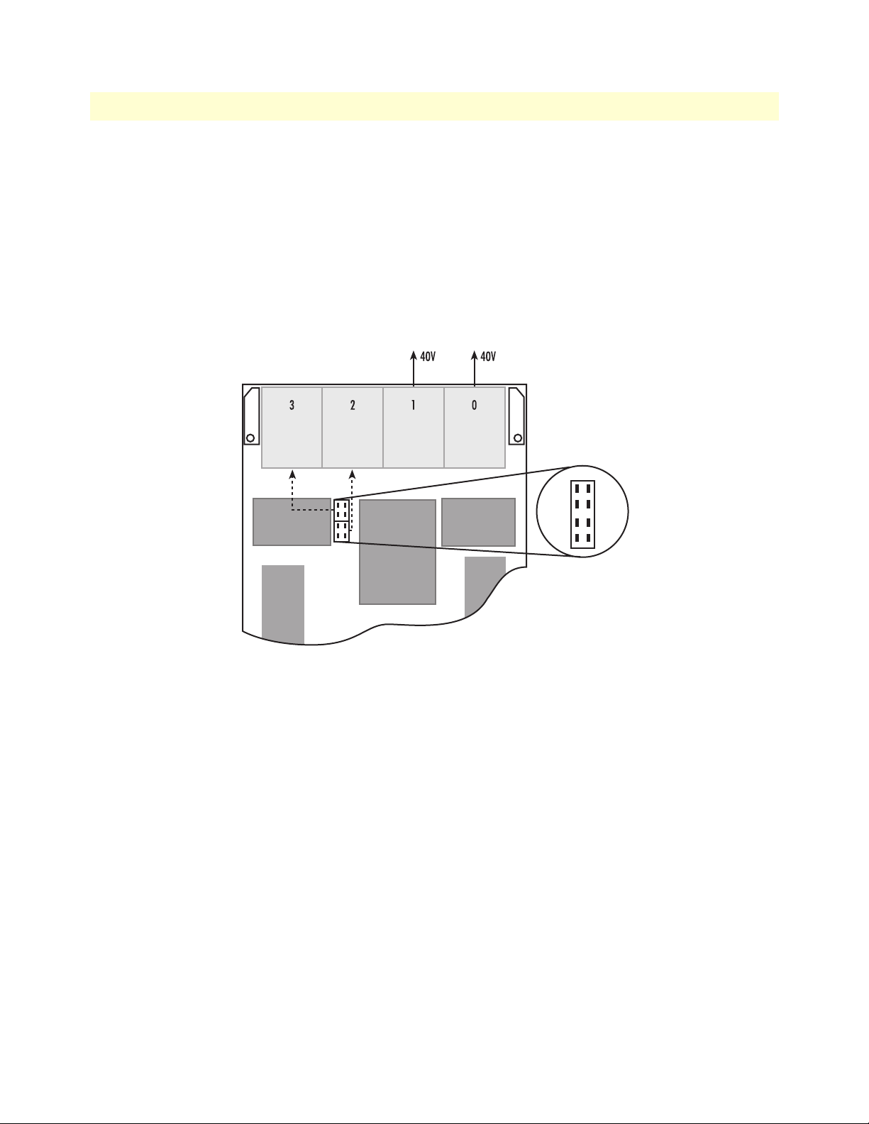
1 • General Information SmartNode 1000 and 2000 Series Getting Started Guide
Jumper settings for IC-4BRV and PM-48V-INT (or PM-40V-INT). The following are possible jumper settings for IC-4BRV and PM-48V-INT (or PM-40V-INT) fitted in SmartNode SmartNode 2000 Series:
• No jumpers are set: this setting is used with ports 2 and 3 configured in USR mode and connected to NTs
as shown in figure 21.
• Upper four jumper pins bridged: this setting is used with port 2 configured as fallback and connected to a
NT as shown in figure 22 on page 43.
• All eight jumper pins bridged: this setting is used with all four ports configured in NET mode and con-
nected to line powered terminals as shown in figure 23 on page 43.
Figure 21. No jumpers set
42 Interface cards descriptions
Page 43
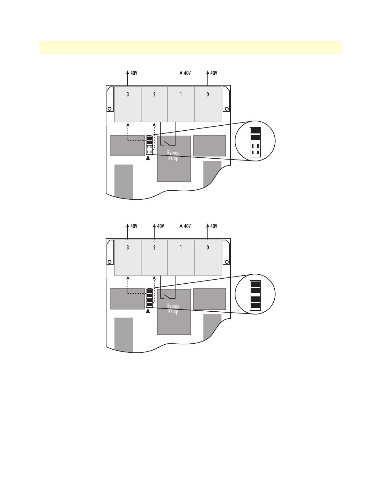
SmartNode 1000 and 2000 Series Getting Started Guide 1 • General Information
Figure 22. Upper four jumper pins bridged
Figure 23. All eight jumper pins bridged
IC-4BRV-8V 8-channel gateway interface card for ISDN BRI
The IC-4BRV-8V is a PMC standard compatible interface card for the SmartNode 2000 series. It provides 4
ISDN BRI interfaces and connects through a PCI packet and PCM circuit interface to the SmartNode base unit.
The IC-4BRV-8V supports up to 8 simultaneous voice or fax calls. It is a flexible ISDN networking card
designed to meet the needs of small enterprises that want to connect their ISDN equipment, such as an ISDN
PBX, via multiple BRI interfaces to a multi-service IP network.
The ISDN interfaces can be configured as user or network side interfaces. In contrast with the IC-4BRV, all
ports can be configured for network or user-side operation. Its on-board, dedicated micro-controller and DSPs
Interface cards descriptions 43
Page 44

1 • General Information SmartNode 1000 and 2000 Series Getting Started Guide
off-load the CPU of the SmartNode 2000 base unit and hence guarantee the conversion of voice/fax circuits
into related IP-packets in real-time with minimal delay and jitter values.
Front panel
The front view of the IC-4BRV-8V interface card is depicted in figure 24. The individual sockets are labeled on
the bezel.
BRI 3
BRI 2
BRI 1
BRI 0
IC-4BRV-8V
BRI 3
BRI 2
BRI 1
Bypass
BRI 0
IC-4BRV-8V
Figure 24. IC-4BRV-8V
Ports
The card provides the four BRI ports whose details are tabulated in table 16. Each one is terminated internally
at 100 ohm. See appendix B, “Cabling” on page 165 for connection cable and appendix C, “Port pin-outs” on
page 177 for pin-out data.
Table 16. IC-4BRV-8V port description
Port Description
BRI 0 ISDN BRI RJ-45 socket that connects the SmartNode with an ISDN device over an S or S/T inter-
face. The pin out and protocol mode is software configurable.
BRI 1 ISDN BRI RJ-45 socket that connects the SmartNode with an ISDN device over an S or S/T inter-
face. The pin out and protocol mode is software configurable.
BRI 2 ISDN BRI RJ-45 socket that connects the SmartNode with an ISDN device over an S or S/T inter-
face. The pin out and protocol mode is software configurable.
BRI 3 ISDN BRI RJ-45 socket that connects the SmartNode with an ISDN device over an S or S/T inter-
face. The pin out and protocol mode is software configurable.
Description
The IC-4BRV-8V interface card provides four ISDN basic rate interface (BRI) ports, together allowing up to 8
ISDN B-channels to work in parallel.
44 Interface cards descriptions
Page 45

SmartNode 1000 and 2000 Series Getting Started Guide 1 • General Information
Operating modes
All four ports can be used in NET or USR modes.
• A NET port is connected to an ISDN terminal, i.e. a telephone or a PBX.
• A USR port performs user side signaling and the pin out corresponds to an ISDN terminal.
S-Bus line power
Some ISDN terminals are powered through the S-Bus. This is usually the case for ISDN phones but not for
PBXs. If you want to connect such a terminal directly to a port of the IC-4BRV-8V, you must install a PM48V-INT (or PM-40V-INT) power supply module. Two steps are required to provide S-Bus line power:
• Install an internal Line Power Module PM-48V-INT (or PM-40V-INT). This is described in section
“Internal PM-48V-INT or PM-40V-INT line power module installation” on page 127.
• Configure the IC-4BRV-8V card’s jumper settings. This procedure is described in the following paragraphs.
Line power jumper settings
A set of jumper pins determines how power is supplied to the BRI ports. The jumper pin block is located on
the IC-4BRV-8V interface card underside (see figure 25 on page 46).
IMPORTANT
Power output on all ports is configurable. BRI ports of the IC4BRV-8V configured in USR mode
Set the jumpers so that line-power is only supplied on those ports
configured in NET mode, i.e. where you want to connect linepowered ISDN terminals.
The jumpers are not accessible when the IC-4BRV-8V card is
installed, you must set the jumpers before installing the card in
the SmartNode 2000 Series device.
must not
supply line-power.
Interface cards descriptions 45
Page 46

1 • General Information SmartNode 1000 and 2000 Series Getting Started Guide
Jumper settings for IC-4BRV-8V. The jumpers for each port are located behind the port connector
(see figure 25):
40V 40V40V 40V
3 2 1 0
Figure 25. Jumpers
Port jumpers can configured as shown in table 17.
Table 17. Jumper configurations
No jumpers are set. In this configuration, no line power is fed to port. Use this setting for
ports when connected to an ISDN NT.
Normal feeding. Use this setting when the port is configured as
nal is attached.
Inverse feeding. Same function as in normal feeding, except that the polarity is inverted
(required in some countries, Japan, for example).
NET
and a line-powered termi-
USR
IC-4BRV-8VR—8-channel gateway interface card for ISDN BRI with hardware bypass (emergency) relay
The IC-4BRV-8VR is a PMC standard compatible interface card for the SmartNode 2000 series. It provides 4
ISDN BRI interfaces and connects through a PCI packet and PCM circuit interface to the SmartNode base
unit.
The specifications for the IC-4BRV-8VR are identical with the IC-4BRV-8V (see section ““IC-4BRV-8V 8-
channel gateway interface card for ISDN BRI” on page 43), with an additional hardware bypass (emergency)
relay. The relay works as follows: If a power failure occurs, the relay connects the interfaces BRI1 and BRI 2
with each other. For this to work as expected:
• BRI 1 must be connected to a telephone terminal or PBX
• BRI 2 must be connected to the ISDN network
46 Interface cards descriptions
Page 47

SmartNode 1000 and 2000 Series Getting Started Guide 1 • General Information
IC-E1V 30-channel E1 gateway interface card for ISDN PRI
The IC-E1V is a PMC standard compatible interface card for the SmartNode 2000 series. It provides one ISDN
PRI interface and connects through a PCI packet and PCM circuit interface to the SmartNode base unit.
The IC-E1V is a high performance ISDN networking card that supports up to 30 simultaneous voice or fax
calls. It meets the requirements of medium and large sized enterprises that want to connect their ISDN equipment, such as an ISDN PBX, via a PRI interface to a multi-service IP network.
The ISDN PRI interfaces can be configured as user or network side interfaces. Its on board dedicated microcontroller and DSPs off load the CPU of the SmartNode 2000 base unit and hence guarantee the conversion of
voice/fax circuits into related IP-packets in real-time with minimal delay and jitter values
Front panel
The front view of the IC-E1V interface card is depicted in figure 26. The LINK LED indicates the status of the
interface. See chapter 11, “Monitoring Status” on page 151 on the LED states.
Figure 26. IC-E1V
Interface
The card provides one PRI port, described in table 18. The connector is terminated at 120 ohm.
Table 18. IC-E1V port description
Port Description
E1 0 RJ-45 connector providing E1 PRI (2.048 Mbps) interface, meeting all requirements of ITU-T recom-
mendations for G.703. Use a shielded E1 interface cable for 120W balanced connections to connect the SmartNode with an NT or ET, e.g. a PBX or LE.
Description
The IC-E1V interface card provides an ISDN PRI interface allowing transfer of up to 30 ISDN voice channels
in parallel.
Interface cards descriptions 47
Page 48

1 • General Information SmartNode 1000 and 2000 Series Getting Started Guide
Interface modes
The interface can be used in two different modes, namely NET or USR. The NET mode means the interface
performs network-side signaling, whereas USR mode means user-side signaling as described in table 19. For
cabling, see Appendix B on page 165.
Table 19. Interface modes
Task NET Mode USR Mode
Clocking Mode Master: generates line clocking Slave: accepts line clocking
Time Slot Interface responsible for time slot selection Interface accepts time slot selection
When changing the interface mode from NET to USR, or USR to NET, the clock source setting is automati-
cally adjusted. For NET the clock becomes master and for USR the clock becomes slave.
You can manually override these default settings of the clock (refer to the Software Configuration Guide). The next
time that the interface mode is changed the clock source changes back automatically to the default again.
IC-E1V-0 E1 gateway interface card for ISDN PRI (circuit switching only)
IC-E1V-0 E1 gateway interface card for ISDN PRI - circuit switching only
This card is based on the IC-E1V interface card (see section “IC-E1V 30-channel E1 gateway interface card for
ISDN PRI” on page 47), but it does not provide VoIP channels. The card supports full ISDN signaling. All B-
Channels (64 kbps time slots) can be used for calls that are within the same card, or between this card and other cards
installed in the same SmartNode Gateway chassis. No VoIP calls can be made to destinations outside the SmartNode
chassis.
IC-E1V-15 15-channel E1 gateway interface card for ISDN PRI
This card is based on the IC-E1V interface card (see section “IC-E1V 30-channel E1 gateway interface card for
ISDN PRI” on page 47). It supports 15 simultaneous VoIP channels. The card supports full ISDN signaling. All
B-Channels (64 kbps time slots) can be used for calls within the same card, or between this card and other cards
installed in the same SmartNode Gateway chassis. VoIP calls are limited to 15 at a time.
IC-T1V 23-channel T1 gateway interface card for ISDN PRI
The IC-T1V is a PMC standard compatible interface card for the SmartNode 2000 series. It provides one
ISDN PRI interface and connects through a PCI packet and PCM circuit interface to the SmartNode base
unit.
The IC-T1V is a high performance ISDN networking card that supports up to 23 simultaneous voice or fax
calls. It meets the requirements of medium and large sized enterprises that want to connect their ISDN equipment, such as an ISDN PBX, via a PRI interface to a multi-service IP network.
The ISDN PRI interfaces can be configured as user or network side interfaces. Its on board dedicated microcontroller and DSPs off load the CPU of the SmartNode 2000 base unit and hence guarantee the conversion of
voice/fax circuits into related IP-packets in real-time with minimal delay and jitter values.
48 Interface cards descriptions
Page 49

SmartNode 1000 and 2000 Series Getting Started Guide 1 • General Information
Front panel
The front view of the IC-T1V interface card is depicted in figure 26. The LINK LED indicates the status of the
interface. See chapter 11, “Monitoring Status” on page 151 for detailed information on the LED states.
Figure 27. IC-T1V
Interface
The card provides one PRI port, described in table 18. The connector is terminated at 120 ohm.
Table 20. IC-E1V port description
Port Description
T1 0 RJ-45 connector providing T1 PRI (1.533 Mbps) interface, meeting all requirements of ITU-T recom-
mendations for G.703. Use a shielded T1 interface cable for 120W balanced connections to connect the SmartNode with an NT or ET, e.g. a PBX or LE.
Description
The IC-T1V interface card provides an ISDN PRI interface allowing transfer of up to 23 ISDN voice channels
in parallel.
Interface cards descriptions 49
Page 50

1 • General Information SmartNode 1000 and 2000 Series Getting Started Guide
Interface modes
The interface can be used in two different modes, namely NET or USR. The NET mode means the interface
performs network-side signaling, whereas USR mode means user-side signaling as described in table 19. For
cabling, see Appendix B on page 165.
Table 21. Interface modes
Task NET Mode USR Mode
Clocking Mode Master: generates line clocking Slave: accepts line clocking
Time Slot Interface responsible for time slot selection Interface accepts time slot selection
When changing the interface mode from NET to USR, or USR to NET, the clock source setting is automati-
cally adjusted. For NET the clock becomes master and for USR the clock becomes slave.
You can manually override these default settings of the clock: see the documents Software Configuration Guide. The
next time that the interface mode is changed the clock source changes back automatically to the default again.
IC-T1V-0 T1 gateway interface card for ISDN PRI (circuit switching only)
This card is based on the IC-T1V interface card (see “IC-T1V 23-channel T1 gateway interface card for ISDN
PRI” on page 48), but it does not provide VoIP channels. The card supports full ISDN signaling. All B-Chan-
nels (64 kbps) can be used for calls within the same card, or between this card and other cards installed in the
same SmartNode Gateway chassis. No VoIP calls can be made can be made to destinations outside the SmartNode chassis.
IC-T1V-15 15-channel T1 gateway interface card for ISDN PRI
This card is based on the IC-T1V interface card (see “IC-T1V 23-channel T1 gateway interface card for ISDN
PRI” on page 48). It provides 15 simultaneous VoIP channels. The card supports full ISDN signaling, and all
B-Channels (64 kbps time slots) can be used for calls within the same card, or between this card and other
cards installed in the same SmartNode Gateway chassis. VoIP calls are limited to 15 at a time.
50 Interface cards descriptions
Page 51

Chapter 2 Product Overview
Chapter contents
Introduction..........................................................................................................................................................53
System model of the SmartNode 1000 and 2000 Series.........................................................................................54
Voice routing.........................................................................................................................................................54
SmartNode deployment.........................................................................................................................................55
Customer premises gateway; multi-service providers .......................................................................................55
Small office or home office (SOHO) .........................................................................................................55
Small and medium enterprise (SME) .........................................................................................................56
Multi-service gateway/router for private enterprise networks ...........................................................................58
Company branch office .............................................................................................................................58
Company headquarters .............................................................................................................................59
IP access to the WAN .....................................................................................................................................59
ISDN Gateway; LAN-based PBX or call center applications ...........................................................................60
LAN-based telephony gateways (GW) .......................................................................................................60
51
Page 52

2 • Product Overview SmartNode 1000 and 2000 Series Getting Started Guide
52
Page 53

SmartNode 1000 and 2000 Series Getting Started Guide 2 • Product Overview
Introduction
The SmartNode 1000 and 2000 series aggregate multiple channels of data and voice user-side traffic for transport over a single wide-area network (WAN) uplink. With one or more ISDN BRI or PRI interfaces, the
SmartNode 1000 (see figure 28) and 2000 (see figure 29) series can be connected to an ISDN PBX or to a local
exchange switch. Moreover, ISDN BRI interfaces can be used to attach ISDN telephones or to connect to an
ISDN NT for voice call fallback or call routing to the PSTN.
Figure 28. System model, SmartNode 1000 Series
Figure 29. System model, SmartNode 2000 Series
Voice is transported as voice over Internet Protocol (VoIP) using the H.323 standards for sending and receiving
audio and data or Patton Electronics’ proprietary ISDN over Internet Protocol (ISoIP) on an IP-based network.
Since both of the Ethernet interfaces of a SmartNode 1000 and 2000 series are fully configurable, it is the application which defines whether an interface is used for WAN or LAN connections.
Depending of the deployment scenario, optional interface cards are available for the expansion slots of SmartNode 2000 series.
Introduction 53
Page 54

2 • Product Overview SmartNode 1000 and 2000 Series Getting Started Guide
Note For information concerning hardware and interface card support see the
SmartWare Software Release Notes for your Software Release and Build
Number.
This chapter contains the following information about the SmartNode Series devices:
• System model of the SmartNode 1000 and 2000 Series
• Voice routing
• Overview of SmartNode deployment as a customer premises gateway supplied by a multi-service provider, a
voice gateway and IP router, or a LAN voice gateway (see page 55)
System model of the SmartNode 1000 and 2000 Series
The system model of Patton SmartNodes is depicted in figure 28 and figure 29 on page 53. The devices have
three main components:
• ISDN switching, with two ISDN base rate interfaces (BRI).
• Gateway (GW), which converts ISDN voice data into Internet Protocol (IP) data streams or voice over IP
(VoIP) and vice-versa. VoIP speech is supported according the H.323 standard and via Patton Networks’
patented ISDN over IP (ISoIP) protocol.
• Router, with on-board Ethernet and other data interfaces which support quality of service (QoS) classes and
type of service (TOS) bit setting. Quality of service enables the router to support multiple traffic classes.
Voice routing
Via its gateway, an Patton SmartNode 1000 and 2000 series device can carry voice data between the ISDN
basic rate or primary rate interfaces and Ethernet or other data interfaces. This facility allows a wide variety of
voice routing scenarios to be realized.
54 System model of the SmartNode 1000 and 2000 Series
Page 55

SmartNode 1000 and 2000 Series Getting Started Guide 2 • Product Overview
SmartNode deployment
Customer premises gateway; multi-service providers
Figure 30, figure 31 on page 56, and figure 32 on page 57 show typical deployment scenarios for the Smart-
Node 1000 and 2000 series used as a customer premises gateway supplied by a multi-service provider.
Small office or home office (SOHO)
Figure 30 depicts a SmartNode 1200 used as a voice gateway and IP router in a SOHO situation. The voice
gateway operates with both H.323 and ISoIP on a call-by-call basis. The SmartNode is connected to the ISDN
NT for voice call fallback or exceptional call routing scenarios via port BRI 0. An ISDN telephone is connected to port BRI 1.
Figure 30. SmartNode 1200 with ISDN phone and ISDN fallback in a SOHO environment
SmartNode deployment 55
Page 56

2 • Product Overview SmartNode 1000 and 2000 Series Getting Started Guide
Small and medium enterprise (SME)
The SmartNode 1400 in figure 31 is set up as a voice gateway and IP router in an SME situation. Both BRI
ports are attached to a local PBX, offering up to four simultaneous voice channels to the IP access network that
is connected to the Ethernet port ETH 0.
Figure 31. SmartNode 1400 attached to PBX via both ISDN BRIs in an SME environment
56 SmartNode deployment
Page 57

SmartNode 1000 and 2000 Series Getting Started Guide 2 • Product Overview
Figure 32 depicts a SmartNode 2000 series used as a voice gateway and IP router in an SME situation. The
optional IC-4BRV interface card’s BRI 2 port is used as an ISDN fallback interface. In case of a power failure,
equipment connected to port BRI 1 is bypassed with a relay to interface BRI 2. It remains operational even if
the SmartNode 2000 series is not powered. Three ports of the PBX are connected to the remaining BRI ports
of the IC-4BRV interface card, providing up to six concurrent ISDN B-channels. The voice data is transferred
via the integrated voice gateway in the SmartNode 2000 series over Ethernet port ETH 0/0. Depending on the
call procedures defined by the software running in the SmartNode 2000 series, voice data is formatted as
H.323 compliant or as ISoIP voice streams.
Figure 32. SmartNode 2000 Series device connected to a PBX via three BRI ports with fallback to PSTN with
one BRI in an SME environment
SmartNode deployment 57
Page 58

2 • Product Overview SmartNode 1000 and 2000 Series Getting Started Guide
Multi-service gateway/router for private enterprise networks
Company branch office
In figure 33 the SmartNode 2000 series with an optional IC-4BRV interface card installed is used as a voice
gateway and IP router in a company branch office.
Figure 33. SmartNode 2000-Series device connected to a PBX via four BRI ports
The IC-4BRV interface card provides four ISDN BRI ports and is frequently used to interconnect existing
ISDN PBXs over an IP network.
All four ports of the PBX are connected to the IC-4BRV interface card BRIs, providing a maximum of eight
concurrent ISDN B-channels. The voice data is transferred via the integrated voice gateway in the SmartNode
2000 series via Ethernet port ETH 0/0. Depending on the call procedures defined by the software running in
the SmartNode 2000 series, voice data is formatted as H.323 compliant or ISoIP voice streams.
58 SmartNode deployment
Page 59

SmartNode 1000 and 2000 Series Getting Started Guide 2 • Product Overview
Company headquarters
In figure 34 the SmartNode 2000 series with an optional IC-E1V interface card installed is used as a voice gate-
way and IP router in a company headquarters.
Figure 34. SmartNode 2000 Series device connected to a PBX via one PRI (with IC-E1V card) into an IP network
The PBX is connected to the PRI port of the IC-E1V interface card, providing up to 30 concurrent ISDN Bchannels. The voice data is transferred via the integrated voice gateway in the SmartNode 2000 series over
Ethernet interface ETH 0/0.
Depending on the call procedures defined by the software running in the SmartNode 2000 series, voice data is
formatted as H.323 compliant or ISoIP voice streams.
IP access to the WAN
In the following figures, a wide-area transmission modem is shown as attached to the IP access network of the
operator via Ethernet port ETH 0 for SmartNode 1000 series or ETH 0/0 for SmartNode 2000 series.
• Figure 30 on page 55
• Figure 31 on page 56
• Figure 32 on page 57
• Figure 33 on page 58
• Figure 34 on page 59
SmartNode deployment 59
Page 60

2 • Product Overview SmartNode 1000 and 2000 Series Getting Started Guide
Data traffic from the LAN attached to ETH 1 for SmartNode 1000 series or to ETH 0/1 for SmartNode 2000
series is routed to the WAN via Ethernet ports ETH 0 or ETH 0/0 respectively. Either standard IP routing or
network address port translation (NAPT) can be configured on the SmartNode according to requirement.
ISDN Gateway; LAN-based PBX or call center applications
LAN-based telephony gateways (GW)
The SmartNode 1400 GW depicted in figure 35 is utilized as a LAN voice gateway. On the local LAN that is
shown connected to Ethernet port ETH 0, H.323 compliant voice applications are installed on hosts acting as
H.323 terminals. An H.323 terminal is an endpoint in the network that provides for real-time, two-way communications with another H.323 terminal or gateway.
Outbound voice traffic is forwarded via the integrated voice gateway of the SmartNode 1400 to the PSTN.
Inbound voice traffic from the PSTN is terminated on the respective host running the H.323 compliant client
application according to the dialed calling number.
The H.323 gatekeeper is responsible for the translation of IP addresses into E.164 phone numbers (and phone
numbers into IP addresses).
Note Hosts on the LAN need to be connected to Ethernet port ETH 0 using a hub.
Figure 35. SmartNode 1400 GW used as LAN voice gateway with H.323 software clients on PCs and
H.323 gatekeeper
60 SmartNode deployment
Page 61

Chapter 3 Planning the installation
Chapter contents
Introduction..........................................................................................................................................................63
Installation checklist ..............................................................................................................................................64
Site Log .................................................................................................................................................................64
Network information ............................................................................................................................................65
Network diagram ............................................................................................................................................65
IP related information .....................................................................................................................................65
ISDN related information ...............................................................................................................................65
S-Bus installation ......................................................................................................................................65
SmartNode BRI port configured in USR mode and connected to an S-Bus ..............................................66
SmartNode BRI port configured in NET mode ........................................................................................66
Installing an S-Bus power supply ...............................................................................................................66
Synchronous serial interface ............................................................................................................................66
Software tools........................................................................................................................................................67
Power source .........................................................................................................................................................67
Where to go next...................................................................................................................................................67
61
Page 62

3 • Planning the installation SmartNode 1000 and 2000 Series Getting Started Guide
62
Page 63

SmartNode 1000 and 2000 Series Getting Started Guide 3 • Planning the installation
Introduction
Before you start the actual installation, it is strongly recommended that you gather all the information needed to
install and set-up the device. See section “Installation checklist” on page 64 for an example of what pre-installment checks you might need to carry out. Having carried out the pre-installation checks enables you to install and
set up your SmartNode 1000 or 2000 series into an existing IP or an ISDN infrastructure with confidence.
Note The chapter covers a variety of SmartNode models that are similar in func-
tionality but which differ in the number of interfaces that are supported.
Therefore, some of the information provided may not apply to your particular SmartNode model.
Note When setting up your SmartNode consider cable length limitations, and
potential electromagnetic interference (EMI) as defined by the applicable
local and international regulations. Ensure that your site is properly prepared
before beginning installation.
Before installing the SmartNode device, the following tasks should be completed:
• Create a network diagram (see section “Network diagram” on page 65)
• Gather IP related information (see section “IP related information” on page 65 for more information)
• Collect ISDN related information (see section “ISDN related information” on page 65)
• Gather synchronous serial interface information (SmartNode 2300 only) (see section “Synchronous serial
interface” on page 66 for more information)
• Install the hardware and software needed to configure the SmartNode. (See section “Synchronous serial
interface” on page 66)
• Verify power source reliability (see section “Power source” on page 67).
When you finish preparing for SmartNode installation, go to the appropriate section to install the device:
• Installing the SmartNode 1200 (see chapter 4, “SmartNode 1200 installation” on page 69)
• Installing the SmartNode 1400 (see chapter 5, “SmartNode 1400 installation” on page 81)
• Installing the SmartNode 2300 (see chapter 6, “SmartNode 2300 installation” on page 91)
• Installing the SmartNode 2400 (see chapter 7, “SmartNode 2400 installation” on page 109)
Introduction 63
Page 64

3 • Planning the installation SmartNode 1000 and 2000 Series Getting Started Guide
Installation checklist
The installation checklist in table 22 lists the tasks for installing a SmartNode 1000 or 2000 series. Make a
copy of this checklist and mark the entries as you complete each task. For each SmartNode 1000 or 2000
series, include a copy of the completed checklist in your site log.
Table 22. Installation checklist
Task Verified by Date
Network information available & recorded in site log
Environmental specifications verified
Site power voltages verified
Installation site pre-power check completed
Required tools available
Additional equipment available
All printed documents available
SmartWare release & build number verified
Rack, desktop, or wall mounting of chassis completed
Initial electrical connections established
ASCII terminal attached to console port
Cable length limits verified
Initial configuration performed
Initial operation verified
Site Log
Patton recommends that you maintain a site log to record all actions relevant to the system, if you do not
already keep such a log. Site log entries might include information as listed in table 23.
Table 23. Site log entries
Entry Description
Installation Make a copy of the installation checklist and insert it into the site log
Upgrades and maintenance Use the site log to record ongoing maintenance and expansion history
Configuration changes Record all changes and the reasons for them
Maintenance; Schedules, requirements, and procedures performed
Comments Notes, and problems
Software Changes and updates to SmartWare software
64 Installation checklist
Page 65

SmartNode 1000 and 2000 Series Getting Started Guide 3 • Planning the installation
Network information
Network connection considerations that you should take into account for planning are provided for several
types of network interfaces are described in the following sections.
Network diagram
Draw a network overview diagram that displays all neighboring IP nodes, serial connected elements and ISDN
components. It is recommended that you keep a copy in the site log (see “Site Log” on page 64 for more infor-
mation on keeping a site log).
IP related information
Before you can set up the basic IP connectivity for your SmartNode 1000 or 2000 series you need to have the
following information:
• IP addresses used for Ethernet LAN and WAN ports
• Subnet mask used for Ethernet LAN and WAN ports
• Lengths of Ethernet cables
• IP addresses of central H.323 gatekeeper
• IP addresses of central PSTN gateway for H.323 and/or ISoIP-based calls
• IP addresses of central TFTP server used for configuration upload and download
ISDN related information
To set up basic ISDN connectivity for your SmartNode 1000 or 2000 series you need to do or know the following:
• Check whether an additional line power is necessary and if an optional Phantom power supply or line
power module needs to be installed
• Clock source for ISDN E1 interface
• Length of the ISDN S-Bus or E1 interface cables
• The block of sequential numbers assigned by your telecom operator that are used for the direct dial inwards
(DDI) numbering plan to be used together with your PBX
• Define a multiple subscriber numbering (MSN) schema to give your individual endpoint a unique phone
number that can be dialed directly
• Check whether an ISDN port is to be configured in USR (TE) or NET (NT) mode
• Check whether an ISDN port is to be configured as point-to-point or point-to-multipoint link
S-Bus installation
When installing an ISDN S-bus and up to eight connected devices, bear in mind that the relevant ITU-T,
ETSI and ANSI standards for your equipment must be met. Your ISDN provider will help you to ensure that
you comply with the relevant standards.
An S-Bus must be terminated at both ends with 100 ohm; such termination should be at the extreme ends of
the bus.
Network information 65
Page 66

3 • Planning the installation SmartNode 1000 and 2000 Series Getting Started Guide
Note Only the one device at the end should be terminated: SmartNode interfaces
are internally terminated at 100 ohm.
It is recommended that a screened cable be used of a type that has been tested to at least ISO/IEC 11801
Category 3.
According to ITU-T the maximum length of flex connecting the bus with terminal equipment may not
exceed 33 feet (10 meters). Some ISDN providers or devices may require a lesser distance, so consult your
suppliers. In accordance with ITU-T the maximum length of the S-bus depends on the delay constant of the
cable. If this is too great, the time sequence of the equipment signals attached to it may be corrupted. The
maximum distance between NT1 and TE is theoretically 656 feet (200 meters), but in practice 492 feet
(150 meters) is the usual maximum.
SmartNode BRI port configured in USR mode and connected to an S-Bus
The SmartNode acts as TE on the S-Bus: usually no other TE are connected on the S-Bus between the NT1
and the SmartNode. The general S-Bus conditions apply, the maximum recommended bus length is 492 feet
(150 meters).
Note SmartNode BRI interfaces are internally terminated at 100 ohms.
SmartNode BRI port configured in NET mode
The SmartNode acts as NT1. The general S-Bus conditions apply, the maximum recommended bus length is
492 feet (150 meters).
Note SmartNode BRI interfaces are internally terminated at 100 ohms.
Installing an S-Bus power supply
If your SmartNode 2000 series needs to be equipped with an optional line power module refer to chapter 8,
“Line power module installation” on page 125 for a more detailed description of this procedure. Check that
the jumper pins are correctly set for your method of using the IC-4BRV interface card (see section “IC-4BRV
8-channel gateway interface card for ISDN BRI” on page 37.
The Interconnecting cables shall be acceptable for external use and shall be
rated for the proper application with respect to voltage, current, anticipated
temperature, flammability, and mechanical serviceability
Synchronous serial interface
The SmartNode 2300 supports the V.35 and X.21 standard for synchronous serial interfaces at speeds up to 2
Mbps. Devices that communicate over a serial interface are divided into two classes:
• Data terminal equipment (DTE): the device at the user end of the user-to-network interface. The DTE
connects to a data network via data DCE, and typically uses clocking signals generated by the DCE.
• Data communications equipment (DCE): the device at the network end of the user-to-network interface.
The DCE provides a physical connection to the network, forwards traffic, and provides a clocking signal
used to synchronize data transmission between DCE and DTE devices.
66 Network information
Page 67

SmartNode 1000 and 2000 Series Getting Started Guide 3 • Planning the installation
The most important difference between these two types of device is that the DCE device supplies the clock signal that paces the communications on the interface.
Note A SmartNode 2300 functions as a DTE.
The synchronous serial port is labeled SERIAL 0/0 on the SmartNode 2300. Before you connect a device to it
you need to check the following:
• Confirm that the device that you are connecting the SmartNode to is a DCE that provides a clock signal on
the synchronous serial port
• Type of connector, male or female, required when connecting to the device port
• Signaling protocol; the device requires X.21 or V.35
Software tools
You will need a PC computer with HyperTerminal or equivalent VT-100 emulation program, or an ASCII terminal (also called a dumb terminal) to configure the software on your SmartNode device.
Power source
If you suspect that your AC power is not reliable, for example if room lights flicker often or there is machinery
with large motors nearby, have a qualified professional test the power. Install a power conditioner if necessary.
Where to go next
When you finish preparing for SmartNode installation, go to the appropriate section to install the device:
• Installing the SmartNode 1200 (see chapter 4, “SmartNode 1200 installation” on page 69)
• Installing the SmartNode 1400 installation (see chapter 5, “SmartNode 1400 installation” on page 81)
• Installing the SmartNode 2300 installation (see chapter 6, “SmartNode 2300 installation” on page 91)
• Installing the SmartNode 2400 installation (see chapter 7, “SmartNode 2400 installation” on page 109)
Software tools 67
Page 68

3 • Planning the installation SmartNode 1000 and 2000 Series Getting Started Guide
68 Where to go next
Page 69

Chapter 4 SmartNode 1200 installation
Chapter contents
Hardware installation ............................................................................................................................................71
Mounting the SmartNode 1200 ............................................................................................................................71
Desktop installation ........................................................................................................................................71
Wall-mounted installation ..............................................................................................................................72
Connecting cables..................................................................................................................................................73
Installing the Ethernet cables ..........................................................................................................................73
Installing the BRI cables ..................................................................................................................................74
External S-Bus power supply .....................................................................................................................76
Installing the power cord .................................................................................................................................79
69
Page 70

4 • SmartNode 1200 installation SmartNode 1000 and 2000 Series Getting Started Guide
70
Page 71

SmartNode 1000 and 2000 Series Getting Started Guide 4 • SmartNode 1200 installation
Hardware installation
SmartNode 1200 installation consists of the following:
• Placing the device at the desired installation location (see section “Mounting the SmartNode 1200” on
page 71)
• Installing the interface and power cables (see section “Connecting cables” on page 73)
When you finish installing the SmartNode 1200, go to chapter 10, “Getting Started with the SmartNode
Device” on page 139.
Mounting the SmartNode 1200
The SmartNode 1200 should be placed in a dry environment with sufficient space to allow air circulation for
cooling.
Note For proper ventilation, leave at least 2 inches (5 cm) to the left, right,
front, and rear of the SmartNode 1200.
The SmartNode 1200 can be installed as follows:
• Placed on a desktop or similar sturdy, flat surface that offers easy access to the cables
• Mounted on a wall
Desktop installation
Do the following to install the SmartNode 1200:
1. Remove one of the rubber pads from the adhesive strip (included in the SmartNode installation kit pack)
and place it on a corner on the bottom of the SmartNode 1200 (see figure 36).
Figure 36. Pads and wall-mounting keyholes locations
Hardware installation 71
Page 72

4 • SmartNode 1200 installation SmartNode 1000 and 2000 Series Getting Started Guide
2. Repeat step 1 to install pads on the remaining three corners on the bottom of the SmartNode 1200.
3. Place the unit on a desktop, shelf or other flat, hard, and secure surface.
Note Allow sufficient space at the rear of the chassis for cable connections. In
addition you should consider the need to access the chassis for future
upgrades, maintenance and troubleshooting. Multiple SmartNodes can be
stacked one atop the other.
Wall-mounted installation
Do the following to install the SmartNode 1200:
1. Using figure 37 as a guide, determine the positions of the mounting holes on the wall and mark the loca-
tions of the mounting holes.
Figure 37. Wall-mounting hole dimensions
Note Mounting hardware is not provided. The installer must determine
which fastener is appropriate for that particular application.
2. Install the (user-provided) wall anchors. Any standard anchoring method may be used, such as wood
screws; butterfly anchors/molly bolts (for installation into a sheetrock/drywall or plasterboard surface); or
expansion bolts (for installation into a concrete or masonry surface). The anchor screw heads must have
just enough clearance to allow the wall-mounting key holes (see figure 36 on page 71) to slip onto them
when hanging the SmartNode 1200.
3. Hang the SmartNode 1200 on the wall-anchor mounting screws.
72 Mounting the SmartNode 1200
Page 73

SmartNode 1000 and 2000 Series Getting Started Guide 4 • SmartNode 1200 installation
Figure 38. SmartNode 1200 connectors
Connecting cables
Installing SmartNode 1200 cables takes place in the following order:
Do not work on the system or connect or disconnect cables during periods of
lightning activity.
The Interconnecting cables shall be acceptable for external use and shall be
rated for the proper application with respect to voltage, current, anticipated
temperature, flammability, and mechanical serviceability
1. Installing the 10Base-T Ethernet cable into ports ETH 0 and ETH 1 (see figure 38) (see “Installing the
Ethernet cables” on page 73).
2. Installing the BRI 0 and BRI 1 cables (see “Installing the BRI cables” on page 74).
3. Installing the power cord (see “Installing the power cord” on page 79).
Installing the Ethernet cables
Ethernet devices (10Base-T) are connected to the SmartNode’s Ethernet ports (see table 24 for port pin-out
listing) via a cable terminated with RJ-45 plugs. Use a cross-over cable to connect to a host (see figure 39 on
page 74), or a straight-through cable to connect to a hub (see figure 40 on page 74).
Table 24. Ethernet 10Base-T (RJ-45) port pin-outs
Pin Signal
1 TX+
2 TX3 RX+
6 RX-
Note Pins not listed are not used.
Connecting cables 73
Page 74

4 • SmartNode 1200 installation SmartNode 1000 and 2000 Series Getting Started Guide
Figure 39. Connecting to a host
Figure 40. Connecting to a hub
Installing the BRI cables
The Interconnecting cables shall be acceptable for external use and shall be
rated for the proper application with respect to voltage, current, anticipated
temperature, flammability, and mechanical serviceability
A straight-through S-Bus cable terminated with RJ-45 plugs is used to connect an ISDN NT or TE to the
SmartNode 1200 BRI ports (see table 25 for port pin-out listing). If you are connecting a BRI to an ISDN
74 Connecting cables
Page 75

SmartNode 1000 and 2000 Series Getting Started Guide 4 • SmartNode 1200 installation
telephone, see figure 41, or see figure 42 on page 76 if you are connecting a BRI to an NT. For BRI ports with
configurable pin outs ensure that the appropriate mode (NET or USR) is configured.
Table 25. BRI (RJ-45) port pin-outs
Pin Signal (USR) Signal (NET )
3 TX+ RX+
4 RX+ TX+
5 RX- TX6 TX- RX-
Note Pins not listed are not used.
Hazardous network voltages are present in the BRI cables. If you detach the
cable, detach the end away from the SmartNode or interface card first to avoid
possible electric shock. Network hazardous voltages may be present on the
device in the area of the BRI port, regardless of when power is turned OFF.
To prevent damage to the system, make certain you connect the
BRI cable to the BRI port only and not to any other RJ-45 socket.
Figure 41. Connecting a BRI to an ISDN telephone
Connecting cables 75
Page 76

4 • SmartNode 1200 installation SmartNode 1000 and 2000 Series Getting Started Guide
Figure 42. Connecting a BRI to an NT
External S-Bus power supply
Many ISDN telephone handsets require that 40-VDC power be supplied via the S-Bus connection. In other
words, they have no separate or built-in power supply. In general, point-to-multipoint ISDN BRI NTs supply
line power to the S-Bus. Point-to-point NTs connected to a PBX generally do not supply line power.
The SmartNode 1200 does not supply S-Bus line power on the BRI ports, however, there are two options to
provide S-Bus line power:
• If one of the BRI ports is connected to an ISDN NT, the power supplied by the NT is fed through to the
other BRI port.
• If line power is not available from the NT, but required for connected terminals, the PM-BRI-EXT S-Bus
Phantom power supply can be used.
Table 26. PM-BRI-EXT S-Bus 40V power supply
Item Phantom Power Supply; PM-BRI-EXT
Voltage Specifications Input 230VAC, Output 40VDC
The PM-BRI-EXT power supply unit is equipped with a transformer
that is specially designed for S-Bus line power. The use of a general
purpose DC power transformer may cause equipment damage.
If you use a Phantom power supply other than that supplied by
Patton Electronics Co., you must ensure that it conforms to ITU
I.430 Section 9.7.3.2.2. which specifies that the maximum current delivered shall not exceed 200mA.
76 Connecting cables
Page 77

SmartNode 1000 and 2000 Series Getting Started Guide 4 • SmartNode 1200 installation
Note The following installation options are available:
• In the absence of an NT the PM-BRI-EXT may be connected
directly to the BRI 0 port on the SmartNode (see figure 43). The
terminals are connected to the BRI 1 port.
• The PM-BRI-EXT is connected to the S-Bus via an S-Bus multi-
socket (see figure 44 on page 78).
Do not plug the Phantom power supply directly into any other port than BRI 0.
Installing it on the Ethernet ports or Console port could result in serious equipment damage.
Figure 43. SmartNode 1200 external 40-VDC power supply
Connecting cables 77
Page 78

4 • SmartNode 1200 installation SmartNode 1000 and 2000 Series Getting Started Guide
Figure 44. SmartNode 1200 external 40-VDC power supply
78 Connecting cables
Page 79

SmartNode 1000 and 2000 Series Getting Started Guide 4 • SmartNode 1200 installation
Installing the power cord
Do the following:
1. Insert the barrel type connector end of the AC power cord into the 100–240 VAC power connector (see
figure 38).
The SmartNode 1200 power supply automatically adjusts to
accept an input voltage from 100 to 240 VAC (50/60 Hz).
Verify that the proper voltage is present before plugging the
power cord into the receptacle. Failure to do so could result in
equipment damage.
Note Do not connect the other end of the power cord to the power outlet at
this time.
2. Verify that the AC power cord included with your router is compatible with local standards. If it is not,
refer to chapter 12, “Contacting Patton for assistance” on page 155 to find out how to replace it with a
compatible power cord.
3. Connect the male end of the power cord to an appropriate power outlet.
4. Verify that the green Power LED is lit (see figure 45).
5. Unplug the power cord from the router to power down the unit.
Figure 45. SmartNode 1200 front panel LEDs
Congratulations, you have finished installing the SmartNode 1200! Now go to chapter 10, “Getting Started
with the SmartNode Device” on page 139.
Connecting cables 79
Page 80

4 • SmartNode 1200 installation SmartNode 1000 and 2000 Series Getting Started Guide
80 Connecting cables
Page 81

Chapter 5 SmartNode 1400 installation
Chapter contents
Hardware installation ............................................................................................................................................83
Mounting the SmartNode 1400 ............................................................................................................................83
Desktop installation ........................................................................................................................................83
Wall-mounted installation ..............................................................................................................................84
Connecting cables..................................................................................................................................................85
Installing the Ethernet cables ..........................................................................................................................85
Installing the BRI cables ..................................................................................................................................86
External S-Bus power supply .....................................................................................................................88
Installing the power cord .................................................................................................................................90
81
Page 82

5 • SmartNode 1400 installation SmartNode 1000 and 2000 Series Getting Started Guide
82
Page 83

SmartNode 1000 and 2000 Series Getting Started Guide 5 • SmartNode 1400 installation
Hardware installation
SmartNode 1400 installation consists of the following:
• Placing the device at the desired installation location (see section “Mounting the SmartNode 1400” on
page 83)
• Installing the interface and power cables (see section “Connecting cables” on page 85)
When you finish installing the SmartNode 1400, go to chapter 10, “Getting Started with the SmartNode
Device” on page 139.
Mounting the SmartNode 1400
The SmartNode 1400 should be placed in a dry environment with sufficient space to allow air circulation for
cooling.
Note For proper ventilation, leave at least 2 inches (5 cm) to the left, right,
front, and rear of the SmartNode 1400.
The SmartNode 1400 can be installed as follows:
• Placed on a desktop or similar sturdy, flat surface that offers easy access to the cables
• Mounted on a wall
Desktop installation
Do the following to install the SmartNode 1400:
1. Remove one of the rubber pads from the adhesive strip (included in the SmartNode installation kit pack)
and place it on a corner on the bottom of the SmartNode 1400 (see figure 46).
Figure 46. Pads and wall-mounting keyholes locations
Hardware installation 83
Page 84

5 • SmartNode 1400 installation SmartNode 1000 and 2000 Series Getting Started Guide
2. Repeat step 1 to install pads on the remaining three corners on the bottom of the SmartNode 1400.
3. Place the unit on a desktop, shelf or other flat, hard, and secure surface.
Note Allow sufficient space at the rear of the chassis for cable connections. In
addition you should consider the need to access the chassis for future
upgrades, maintenance and troubleshooting. Multiple SmartNodes can be
stacked one atop the other.
Wall-mounted installation
Do the following to install the SmartNode 1400:
1. Using figure 47 as a guide, determine the positions of the mounting holes on the wall and mark the loca-
tions of the mounting holes.
Figure 47. Wall-mounting hole dimensions
Note Mounting hardware is not provided. The installer must determine
which fastener is appropriate for that particular application.
2. Install the (user-provided) wall anchors. Any standard anchoring method may be used, such as wood
screws; butterfly anchors/molly bolts (for installation into a sheetrock/drywall or plasterboard surface); or
expansion bolts (for installation into a concrete or masonry surface). The anchor screw heads must have
just enough clearance to allow the wall-mounting key holes (see figure 46 on page 83) to slip onto them
when hanging the SmartNode 1400.
3. Hang the SmartNode 1400 on the wall-anchor mounting screws.
84 Mounting the SmartNode 1400
Page 85

SmartNode 1000 and 2000 Series Getting Started Guide 5 • SmartNode 1400 installation
Figure 48. SmartNode 1400 connectors
Connecting cables
Installing SmartNode 1400 cables takes place in the following order:
Do not work on the system or connect or disconnect cables during periods of
lightning activity.
The Interconnecting cables shall be acceptable for external use and shall be
rated for the proper application with respect to voltage, current, anticipated
temperature, flammability, and mechanical serviceability
1. Installing the 10Base-T Ethernet cable into ports ETH 0 and ETH 1 (see figure 48) (see “Installing the
Ethernet cables” on page 85).
2. Installing the BRI 0 and BRI 1 cables (see “Installing the BRI cables” on page 86).
3. Installing the power cord (see “Installing the power cord” on page 90).
Installing the Ethernet cables
Ethernet devices (10Base-T) are connected to the SmartNode’s Ethernet ports (see table 27 for port pin-out
listing) via a cable terminated with RJ-45 plugs. Use a cross-over cable to connect to a host (see figure 49 on
page 86), or a straight-through cable to connect to a hub (see figure 50 on page 86).
Table 27. Ethernet 10Base-T (RJ-45) port pin-outs
Pin Signal
1 TX+
2 TX3 RX+
6 RX-
Note Pins not listed are not used.
Connecting cables 85
Page 86

5 • SmartNode 1400 installation SmartNode 1000 and 2000 Series Getting Started Guide
Figure 49. Connecting to a host
Figure 50. Connecting to a hub
Installing the BRI cables
The Interconnecting cables shall be acceptable for external use and shall be
rated for the proper application with respect to voltage, current, anticipated
temperature, flammability, and mechanical serviceability
A straight-through S-Bus cable terminated with RJ-45 plugs is used to connect an ISDN NT or TE to the
SmartNode 1400 BRI ports (see table 28 for port pin-out listing). If you are connecting a BRI to an ISDN
86 Connecting cables
Page 87

SmartNode 1000 and 2000 Series Getting Started Guide 5 • SmartNode 1400 installation
telephone, see figure 51, or see figure 52 on page 88 if you are connecting a BRI to an NT. For BRI ports with
configurable pin outs ensure that the appropriate mode (NET or USR) is configured.
Table 28. BRI (RJ-45) port pin-outs
Pin Signal (USR) Signal (NET )
3 TX+ RX+
4 RX+ TX+
5 RX- TX6 TX- RX-
Note Pins not listed are not used.
Hazardous network voltages are present in the BRI cables. If you detach the
cable, detach the end away from the SmartNode or interface card first to avoid
possible electric shock. Network hazardous voltages may be present on the
device in the area of the BRI port, regardless of when power is turned OFF.
To prevent damage to the system, make certain you connect the
BRI cable to the BRI port only and not to any other RJ-45 socket.
Figure 51. Connecting a BRI to an ISDN telephone
Connecting cables 87
Page 88

5 • SmartNode 1400 installation SmartNode 1000 and 2000 Series Getting Started Guide
Figure 52. Connecting a BRI to an NT
External S-Bus power supply
Many ISDN telephone handsets require that 40-VDC power be supplied via the S-Bus connection. In other
words, they have no separate or built-in power supply. In general, point-to-multipoint ISDN BRI NTs supply
line power to the S-Bus. Point-to-point NTs connected to a PBX generally do not supply line power.
The SmartNode 1400 does not supply S-Bus line power on the BRI ports, however, there are two options to
provide S-Bus line power:
• If one of the BRI ports is connected to an ISDN NT, the power supplied by the NT is fed through to the
other BRI port.
• If line power is not available from the NT, but required for connected terminals, the PM-BRI-EXT S-Bus
Phantom power supply can be used.
Table 29. PM-BRI-EXT S-Bus 40V power supply
Item Phantom Power Supply; PM-BRI-EXT
Voltage Specifications Input 230VAC, Output 40VDC
The PM-BRI-EXT power supply unit is equipped with a transformer
that is specially designed for S-Bus line power. The use of a general
purpose DC power transformer may cause equipment damage.
If you use a Phantom power supply other than that supplied by
Patton Electronics Co., you must ensure that it conforms to ITU
I.430 Section 9.7.3.2.2. which specifies that the maximum current delivered shall not exceed 200mA.
88 Connecting cables
Page 89

SmartNode 1000 and 2000 Series Getting Started Guide 5 • SmartNode 1400 installation
Note The PM-BRI-EXT is connected to the S-Bus via an S-Bus multi-
socket.(see figure 53).
Do not plug the Phantom power supply directly into any other port than BRI 0.
Installing it on the Ethernet ports or Console port could result in serious equipment damage.
Figure 53. SmartNode 1400 external 40-VDC power supply
Connecting cables 89
Page 90

5 • SmartNode 1400 installation SmartNode 1000 and 2000 Series Getting Started Guide
Installing the power cord
Do the following:
1. Insert the barrel type connector end of the AC power cord into the 100–240 VAC power connector (see
figure 48).
The SmartNode 1400 power supply automatically adjusts to
accept an input voltage from 100 to 240 VAC (50/60 Hz).
Verify that the proper voltage is present before plugging the
power cord into the receptacle. Failure to do so could result in
equipment damage.
Note Do not connect the other end of the power cord to the power outlet at
this time.
2. Verify that the AC power cord included with your router is compatible with local standards. If it is not,
refer to chapter 12, “Contacting Patton for assistance” on page 155 to find out how to replace it with a
compatible power cord.
3. Connect the male end of the power cord to an appropriate power outlet.
4. Verify that the green Power LED is lit (see figure 54).
5. Unplug the power cord from the router to power down the unit.
Figure 54. SmartNode 1400 front panel LEDs
Congratulations, you have finished installing the SmartNode 1400! Now go to chapter 10, “Getting Started
with the SmartNode Device” on page 139.
90 Connecting cables
Page 91

Chapter 6 SmartNode 2300 installation
Chapter contents
Hardware installation ............................................................................................................................................93
Mounting the SmartNode 2300 ............................................................................................................................93
Desktop installation ........................................................................................................................................94
Rack-mounted installation ..............................................................................................................................94
Connecting cables..................................................................................................................................................96
Installing the Ethernet cables ..........................................................................................................................97
Installing the serial interface cable ...................................................................................................................98
Installing the interface card cables .................................................................................................................101
Installing the IC-4FXS interface card cables ............................................................................................101
Installing the IC-4BRV-8V interface card cables .....................................................................................102
Installing the IC-E1V interface card cables ..............................................................................................105
Installing the IC-T1V interface card cables ..............................................................................................106
Installing the power cord ...............................................................................................................................107
91
Page 92

6 • SmartNode 2300 installation SmartNode 1000 and 2000 Series Getting Started Guide
92
Page 93

SmartNode 1000 and 2000 Series Getting Started Guide 6 • SmartNode 2300 installation
Hardware installation
SmartNode 2300 installation consists of the following:
Note If you will be installing the 48V line power module prior to installing
an interface card or ISDN S-Bus, refer to chapter 8, “Line power
module installation” on page 125.
• Installing an interface card (if the card was not installed at the factory). Refer to chapter 9, “Interface card
installation” on page 133 to install the card, then return to this chapter.
• Placing the device at the desired installation location (see section “Mounting the SmartNode 2300” on
page 93)
• Installing the interface and power cables (see section “Connecting cables” on page 96)
When you finish installing the SmartNode 2300, go to chapter 10, “Getting Started with the SmartNode
Device” on page 139.
Mounting the SmartNode 2300
The SmartNode 2300 should be placed in a dry environment with sufficient space to allow air circulation
for cooling.
Note For proper ventilation, leave at least 2 inches (5 cm) to the left, right,
front, and rear of the SmartNode 2300.
The SmartNode 2300 can be installed as follows:
• Placed on a desktop or similar sturdy, flat surface that offers easy access to the cables
• Mounted inside a 19-inch equipment rack
Note To prevent overheating we recommend that the SmartNode 2300 not
be installed in a closed rack or in a room that is not properly ventilated or air-conditioned.
Hardware installation 93
Page 94

6 • SmartNode 2300 installation SmartNode 1000 and 2000 Series Getting Started Guide
Desktop installation
Do the following to install the SmartNode 2300:
1. Remove one of the rubber pads from the adhesive strip (included in the SmartNode installation kit pack)
and place it on a corner on the bottom of the SmartNode 2300 (see figure 55).
Figure 55. Pad locations
2. Repeat step 1 to install pads on the remaining three corners on the bottom of the SmartNode 2300.
3. Place the unit on a desktop, shelf or other flat, hard, and secure surface.
Note Allow sufficient space at the rear of the chassis for cable connections. In
addition you should consider the need to access the chassis for future
upgrades, maintenance and troubleshooting. Multiple SmartNodes can be
stacked one atop the other.
Rack-mounted installation
For rack-mounting, screw holes are provided at standard mounting positions for industry-standard 19-inch
equipment racks.
Note The SN2300 requires AC power 100–40V, 50/60Hz. Its power dissi-
pation is 10W. It should be installed in an open rack wherever possible. If cabinet installation is unavoidable then ensure that the cabinet
has adequate ventilation.
Install the rack-mount brackets before you install the SmartNode 2300 in the rack. When installing multiple
SmartNode 2300s in one rack, we recommend that you leave one height unit (2.54 cm/1 inch) of clear space
between two devices. Two rack mounting brackets and eight screws for attaching the brackets to the chassis are
provided. The screws for installing the chassis in a rack are not included.
94 Mounting the SmartNode 2300
Page 95

SmartNode 1000 and 2000 Series Getting Started Guide 6 • SmartNode 2300 installation
Do the following to mount a SmartNode 2300 in a 19-inch rack:
1. Locate the two angled mounting brackets included in the installation kit pack. The bracket (see figure 56)
is designed so you can have the 1.5 cm flange facing to the front or to the rear. There are four holes for
countersunk screws on the long side of the bracket.
Figure 56. SmartNode 2300 rack mounting bracket location holes
2. Attach a bracket to each side of the SmartNode 2300 with the four self-tapping screws provided. There are
three mounting positions for the brackets (positions A, B, and C as shown in figure 56 on page 95), so
choose the one that best suits your requirements.
Mounting the SmartNode 2300 95
Page 96

6 • SmartNode 2300 installation SmartNode 1000 and 2000 Series Getting Started Guide
3. Install the unit into the rack using the user-provided rack mounting hardware.
Figure 57. SmartNode 2300 connectors
Connecting cables
Installing SmartNode 2300 cables takes place in the following order:
Do not work on the system or connect or disconnect cables during periods of
lightning activity.
The Interconnecting cables shall be acceptable for external use and shall be
rated for the proper application with respect to voltage, current, anticipated
temperature, flammability, and mechanical serviceability
1. Installing the 10Base-T Ethernet cable into port ETH 0/1 or 10/100Base-T Ethernet cable into port ETH
0/0 (see figure 57) (see “Installing the Ethernet cables” on page 97)
2. Installing the serial interface cable into port SERIAL 0/0 (see “Installing the serial interface cable” on
page 98)
3. Installing the interface card cables (see “Installing the interface card cables” on page 101)
4. Installing the power cord (see “Installing the power cord” on page 107)
96 Connecting cables
Page 97

SmartNode 1000 and 2000 Series Getting Started Guide 6 • SmartNode 2300 installation
Installing the Ethernet cables
The Interconnecting cables shall be acceptable for external use and shall be
rated for the proper application with respect to voltage, current, anticipated
temperature, flammability, and mechanical serviceability
Ethernet devices (10Base-T and 100Base-T) are connected to the SmartNode’s Ethernet ports (see table 30 for
port pin-out listing) via a cable terminated with RJ-45 plugs. Use a cross-over cable to connect to a host (see
figure 58), or a straight-through cable to connect to a hub (see figure 59 on page 98).
Table 30. Ethernet 10Base-T (RJ-45) port pin-outs
Pin Signal
1 TX+
2 TX3 RX+
6 RX-
Note Pins not listed are not used.
Figure 58. Connecting to a host
Connecting cables 97
Page 98

6 • SmartNode 2300 installation SmartNode 1000 and 2000 Series Getting Started Guide
Figure 59. Connecting to a hub
Installing the serial interface cable
The Interconnecting cables shall be acceptable for external use and shall be
rated for the proper application with respect to voltage, current, anticipated
temperature, flammability, and mechanical serviceability
Serial devices (V.35 or X.21) are connected to the SmartNode’s serial ports (see table 31 for port pin-out
listing) via a cable terminated at the SmartNode 2300 with a DB-25 connector.
Table 31. Serial port V.35 and X.21 signals
Signal V.35 Signal X.21
Pin Description Pin Description
1 Frame Ground 7 Signal Ground
4 DCD 9 RXDa
6 DTR 10 RXDb
7 Signal Ground 11 TXDb
8 RTS 12 TXDa
9 RXDa 13 CNTb
10 RXDb 14 CNTa
11 TXDb 16 INDb
98 Connecting cables
Page 99

SmartNode 1000 and 2000 Series Getting Started Guide 6 • SmartNode 2300 installation
Table 31. Serial port V.35 and X.21 signals
Signal V.35 Signal X.21
Pin Description Pin Description
12 TXDa 21 SETb
16 TXCb 22 SETa
21 RXCb 23 INDa
22 RXCa
23 TXCa
25 CTS
Figure 60 shows the cables that are required to connect the serial port of a SmartNode 2300 to a standard X.21
or V.35 network termination unit (NTU).
Connecting cables 99
Page 100

6 • SmartNode 2300 installation SmartNode 1000 and 2000 Series Getting Started Guide
Figure 60. V.35 and X.21 modem connection
Note Some NTUs have non-standard or mirrored connections and require
special cables. Consult the NTU maker’s product documentation.
100 Connecting cables
 Loading...