

Page 1
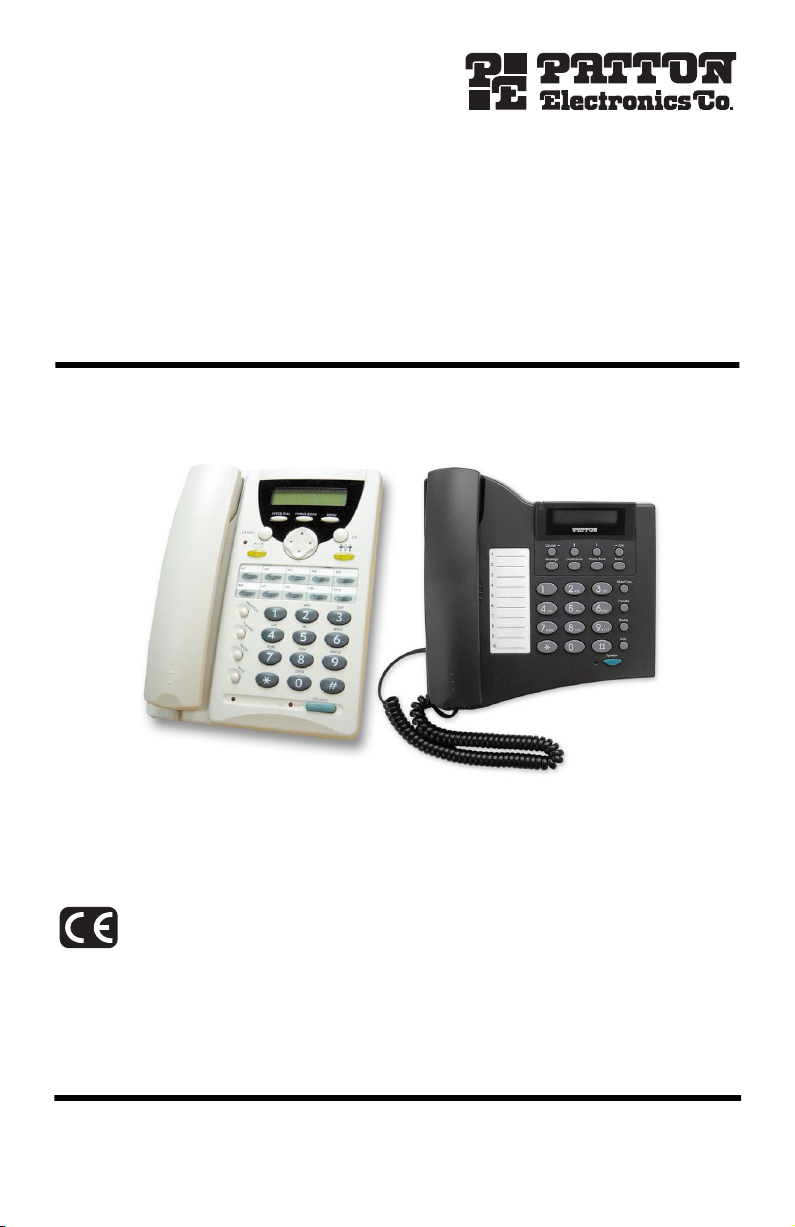
SmartLink 4050 Series
VoIP SIP Phone
SL4050/10 10-Line & SL4050/2 2-Line
Quick Start Guide
SL 4050/10 SL4050/2
Approval
The Model SL4050 phones are not approved for, and are not intended for, connection to the Public Switched
Telephone Network (PSTN).
Document Number:
Part Number:
Revised:
09403U7-001 Rev. C
July 21, 2005
07MSL4050-QS
Sales Office:
Technical Support:
E-mail:
WWW:
+1 (301) 975-1000
+1 (301) 975-1007
support@patton.com
www.patton.com
Page 2

WARNING
• The SmartLink SIP Phone contains no user serviceable parts. The
equipment shall be returned to Patton Electronics for repairs, or
repaired by qualified service personnel.
• Mains Voltage: Do not open the case when the power cord is
attached. The mains outlet that is utilized to power the SmartLink SIP
Phone shall be within 10 feet (3 meters) of the device, shall be easily
accessible, and protected by a circuit breaker.
• Do not work on the system or connect or disconnect cables during
periods of lightning activity.
• Ultimate disposal of this equipment must be handled according to all
applicable national laws and regulations.
2
SmartLink 4050 Series Quick Start Guide
Page 3
1.0 Quick Start
The interconnecting cables shall be acceptable for external use and shall be rated for
the proper application with respect to voltage, current, anticipated temperature, flammability, and mechanical serviceability.
CAUTION
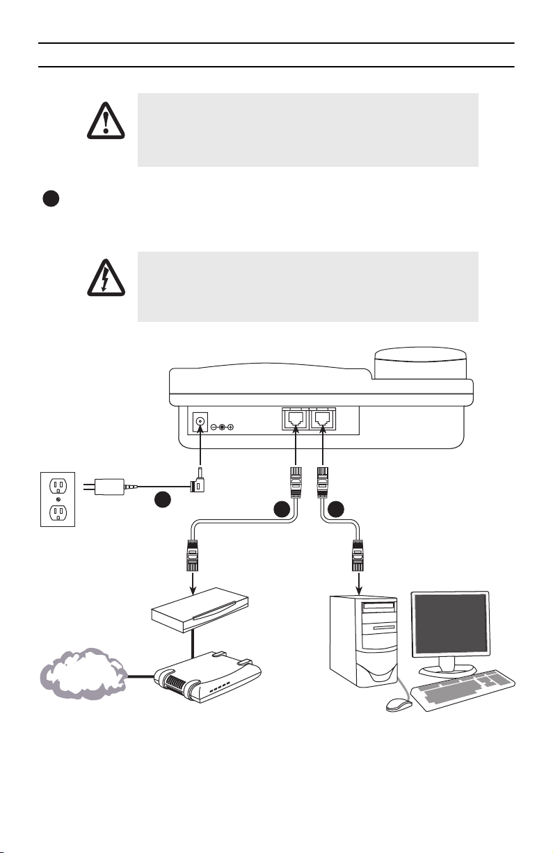
Plug one end of the Ethernet cable included with the VoIP SIP phone into the LAN port on the SIP phone
1
(see
figure 1
for SL4050/10 or
into the xDSL modem or cable modem (or into an optional router or hub).
Do not work on the system or connect or disconnect cables during periods
of lightning activity.
WARNING
figure 2
on page 4 for SL4050/2). Plug the other end of the cable
Power adapter
3
Ethernet Cable (included with
SL 4050/10 phone)
Router/Hub
(optional)
Internet or
optional WAN
Figure 1.
SmartLink 4050 Series Quick Start Guide
DC IN 5V
PowerCable LAN RX TX
LAN PC
Cable/xDSL
modem
Connecting the SL4050/10 SIP Phone
SmartLink 4050/10 VoIP SIP Phone
21
Ethernet Cable (optional)
PC (optional)
3
Page 4

If you will not be connecting a PC to the phone, go to step 3. Otherwise, connect an Ethernet cable into
2
3
the PC port of the SIP phone (see
figure 1
on page 3 for SL4050/10 or
figure 2
for SL4050/2). Plug
the other end of the cable into the Ethernet port on the PC.
SmartLink 4050/2 VoIP SIP Phone
LAN PC
DC IN 5V
Power adapter
21
Ethernet Cable (included with
Ethernet Cable (optional)
SL 4050/2 phone)
Router/Hub
(optional)
Internet or
optional WAN
PowerCable LAN RX TX
Cable/xDSL
Figure 2.
modem
Connecting the SL4050/2 SIP Phone
PC (optional)
Plug the power adapter barrel connector into the power connector on the SIP phone (see
page 3 for SL4050/10 or
figure 2
for SL4050/2). Plug the other end of the power adapter into an AC
electrical outlet.
3
figure 1
on
4
SmartLink 4050 Series Quick Start Guide
Page 5

2.0 Setting up the VoIP SIP phone
Note
You can stop the setup process at any time by pressing
by pressing
the menu screen if there are no inputs from the user.
MENU + CANCEL
to quit without saving. The phone will automatically time-out and exit
MENU + OK
to save any changes and exit, or
Use left and right arrows on the control pad to select
used as a backspace key to delete characters.
ENABLE
or
DISABLE
. The left arrow key can also be
SmartLink 4050 Series Quick Start Guide
Figure 3.
Menu summary, page 1 of 2
5
Page 6

Figure 4.
Menu summary, page 2 of 2
6
SmartLink 4050 Series Quick Start Guide
Page 7

3.0 Additional Information
The complete
can also be downloaded for viewing from
SmartLink 4050 Getting Started Guide
is located on the CD-ROM that came with your SIP phone. It
www.patton.com
.
SmartLink 4050 Series Quick Start Guide
7
Page 8

Copyright statement
Copyright © 2005, Patton Electronics Company. All rights reserved.
The information in this document is subject to change without notice. Patton Electronics assumes no
liability for errors that may appear in this document.
Trademarks statement
The term
SmartLink
is a trademark of Patton Electronics Company. All other trademarks presented in this docu-
ment are the property of their respective owners.
Patton support headquarters in the USA
•
Online support: Available at
•
E-mail support: E-mail sent to
•
Telephone support: Standard telephone support is available five days a week—from
5:00 pm EST (1300
•
Support via VoIP: Contact Patton free of charge by using a VoIP ISP phone to call
•
Fax:
+1 (253) 663-5693
www.patton.com
support@patton.com
to
2200 UTC/GMT
will be answered within 1 business day
)—by calling
+1 (301) 975-1007
8:00 am
to
sip:support@patton.com
Alternate Patton support for Europe, Middle East, and Africa (EMEA)
Telephone support: Standard telephone support is available five days a week—from
•
5:00 pm CET (0900
Fax:
+41 (0)31 985 25 26
•
to
1800 UTC/GMT
)—by calling
+41 (0)31 985 25 55
8:00 am
to
Note
For additional service and support information, refer to the “Contacting Patton for assistance” chapter
of the
SmartLink 4050 Series Getting Started Guide
phone or available online at
www.patton.com
located on the CD-ROM that came with your SIP
.
For additional warranty, trademark, compliance, and technical support information, refer to the
Series Getting Started Guide
at
www.patton.com
8
located on the CD-ROM that came with your SIP phone or available online
.
SmartLink 4050 Series Quick Start Guide
SmartLink 4050
 Loading...