

Page 1
USER
MANUAL
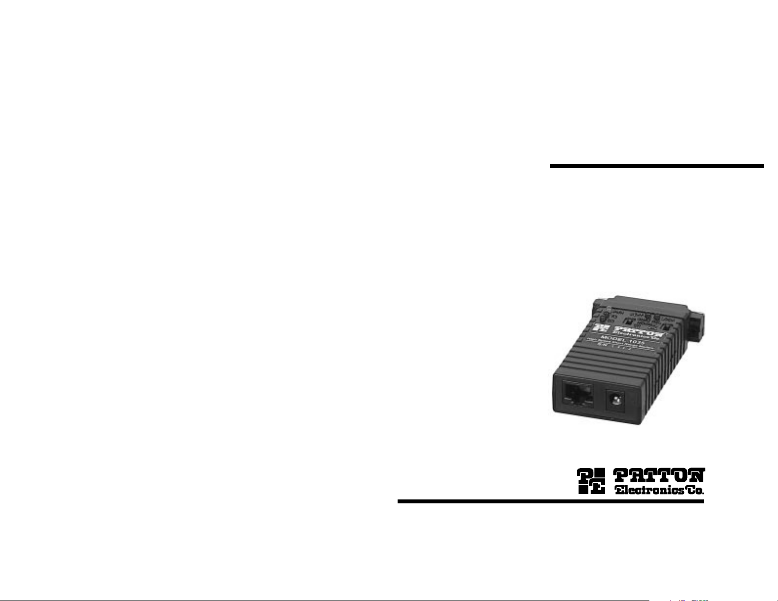
MODEL 1035
Powered High Speed
Short Range Modem
RS-232 and V.35 versions
Part# 07M1035-A
Doc# 054071UA
Revised 7/6/95
SALES OFFICE
(301) 975-1000
TECHNICAL SUPPORT
(301) 975-1007
http://www.patton.com
Page 2

1.0 WARRANTY INFORMATION
2.0 GENERAL INFORMATION
Patton Electronics warrants all Model 1035 components to be
free from defects, and will—at our option—repair or replace the product
should it fail within one year from the first date of shipment.
This warranty is limited to defects in workmanship or materials, and
does not cover customer damage, abuse or unauthorized modification.
If this product fails or does not perform as warranted, your sole
recourse shall be repair or replacement as described above. Under no
condition shall Patton Electronics be liable for any damages incurred
by the use of this product. These damages include, but are not limited
to, the following: lost profits, lost savings and incidental or
consequential damages arising from the use of or inability to use this
product. Patton Electronics specifically disclaims all other warranties,
expressed or implied, and the installation or use of this product shall be
deemed an acceptance of these terms by the user.
1.1 RADIO AND TV INTERFERENCE
The Model 1035 generates and uses radio frequency energy, and if
not installed and used properly—that is, in strict accordance with the
manufacturer's instructions—may cause interference to radio and
television reception. The Model 1035 has been tested and found to
comply with the limits for a Class A computing device in accordance
with the specifications in Subpart J of Part 15 of FCC rules, which are
designed to provide reasonable protection from such interference in a
commercial installation. However, there is no guarantee that
interference will not occur in a particular installation. If the Model 1035
does cause interference to radio or television reception, which can be
determined by disconnecting the unit, the user is encouraged to try to
correct the interference by one or more of the following measures:
moving the computing equipment away from the receiver, re-orienting
the receiving antenna and/or plugging the receiving equipment into a
different AC outlet (such that the computing equipment and receiver are
on different branches).
1.2 SERVICE
All warranty and non-warranty repairs must be returned freight
prepaid and insured to Patton Electronics. All returns must have a
Return Materials Authorization number on the outside of the shipping
container. This number may be obtained from Patton Electronics
Technical Service at (301) 975-1007.
Packages received without an
RMA number will not be accepted.
Patton Electronics' technical staff is also available to answer any
questions that might arise concerning the installation or use of your
Model 1035. Technical Service hours: 8AM to 5PM EST, Monday
through Friday.
1
Thank you for your purchase of this Patton Electronics product.
This product has been thoroughly inspected and tested and is
warranted for One Year parts and labor. If any questions or problems
arise during installation or use of this product, please do not hesitate to
contact Patton Electronics Technical Support at (301) 975-1007.
2.1 FEATURES
• Switch-selectable carrier control
• Synchronous data rates of 32, 56 and 64 Kbps
• Distances to 6 miles
• Point-to-point or multipoint operation
• V.54 loopback tests and V.52 compliant BER tests
• Five easy-to-read LED indicators
• AC powered
• Transformer isolation
• Silicon Avalanche Diode surge protection
2.2 DESCRIPTION
The Model 1035 high speed short range modem supports
synchronous communication at data rates of 32, 56 and 64 Kbps.
Transmit clock options are internal, external and receive loopback
clock. Deriving power from a 7.5V wall-mount transformer, the Model
1035 supports distances to 6 miles over unconditioned twisted pair.
The Model 1035 incorporates two V.54 test modes (local analog
loop and remote digital loop), which can be activated via the RS-232 or
V.35 interface or by a tiny, externally accessible switch. Additionally, a
built-in V.52 BER test generator outputs 511 and 511E bit patterns
which can also be controlled by a switch on the case. Five easy-toread LED indicators monitor power, transmit data, carrier detect, test
mode and test pattern. For protection against ground loops and
transient surges, the Model 1035 incorporates both isolation
transformers and Silicon Avalanche Diode surge suppressors.
Housed in a miniature ABS plastic case, the Model 1035 comes
equipped with a female DB-25 connector and a choice of twisted pair
interfaces (RJ-11 jack or RJ-45 jack). The Model 1035 is available in
an RS-232/V.24 version and a CCITT V.35 version.
2
Page 3
3.0 CONFIGURATION
The Model 1035 provides sixteen configuration switches, which
allow selection of data rates, clocking methods, V.54 test modes,
RTS/CTS delay and DTE control of test functions. This section
describes switch locations and explains all possible switch
configurations.
3.1 CONFIGURATION SWITCHES
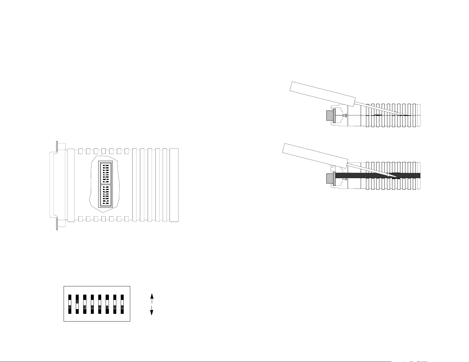
The Model 1035’s unique set of sixteen internal DIP switches
allows configuration to an extremely wide range of applications. These
switches are grouped into two eight-switch sets and are located on the
inside of the unit (Figure 1). For instructions on opening the Model
1035 case, see Section 3.2.
SW2
OFF
12345678
SW1
OFF
12345678
3.2 OPENING THE CASE
Open the unit by gently inserting a screwdriver into the special pry
slot on the plastic case (below). You don't have to worry about
breaking the plastic.
3.3 SWITCH SETTINGS
Figure 1. The inside of the Model 1035
Figure 2 shows the orientation of the switches, including the
ON/OFF positions.
12345678
OFF
Figure 2. Close up of configuration switches
DHS-8
ON
OFF
3
All possible settings for the Model 1035’s configuration switches
are presented in the summary table and descriptions on the following
pages. If you have additional questions regarding configuration,
contact Patton Technical Support at (301) 975-1007.
4
Page 4

SWITCH SET SW1
SW1-8: V.54 Enable/Disable
The configuration switches on switch set SW1 set analog
loopback, digital loopback and V.54 enable/disable. The default
settings are summarized in Figure 3 (below).
SW1 SUMMARY TABLE
Position Function Factory Default
SW1-1 DTE Control of Analog Loopback On Enabled
SW1-2 DTE Control of Digital Loopback On Enabled
SW1-3 Not Used Off n/a
SW1-4 Not Used Off n/a
SW1-5 Not Used Off n/a
SW1-6 Not Used Off n/a
SW1-7 Not Used Off n/a
SW1-8 V.54 Enable/Disable Off Enabled
Figure 3. Summary of DIP switch settings for set SW1
SW1-1: DTE Initiation of Local Analog Loopback Test
The setting for switch SW1-1 determines whether or not the Model
1035’s local analog loopback test can be initiated by raising pin 18 on
the DTE.
SW1-1
On Pin 18 initiation enabled
Off Pin 18 initiation disabled
Setting
The setting for switch SW1-8 determines whether or not the Model
1035’s V.54 circuits are enabled.
SW1-8 Setting
On V.54 test functions disabled
Off V.54 test functions enabled
SWITCH SET SW2
The configuration switches on switch set SW2 set data rate, clock
source, carrier control and RTS/CTS delay. The default settings are
summarized in Figure 4.
SW2 SUMMARY TABLE
Position Function Factory Default
SW2-1 Data Rate Off
SW2-2 Data Rate On
SW2-3 Data Rate Off
SW2-4 Clock Source On
SW2-5 Clock Source On
SW2-6 Carrier Control Off Constantly On
SW2-7 RTS/CTS Delay On
SW2-8 RTS/CTS Delay On
Figure 4. Summary of DIP switch settings for set SW2
}
}
}
56 Kbps
Internal
7 ms
SW1-2: DTE Initiation of Remote Digital Loopback Test
The setting for switch SW1-2 determines whether or not the Model
1035’s remote digital test can be initiated by raising pin 21 on the DTE.
SW1-2 Setting
On Pin 21 initiation enabled
Off Pin 21 initiation disabled
SW1-3 through SW1-7: Not Used
(continued)
5
SW2-1 through SW2-3: Data Rate Setting
Switches SW2-1 through SW2-3 are set in combination to
determine the synchronous data rate for the Model 1035.
SW2-1 SW2-2 SW2-3 Setting
On Off Off 64 Kbps
Off On Off 56 Kbps
Off Off On 32 Kbps
(continued)
6
Page 5

SW2-4 and SW2-5: Clock Source
Switches SW2-4 and SW2-5 are set in combination to determine
the synchronous clock source for the Model 1035.
SW2-4 SW2-5 Setting
On On Internal transmit clock
Off On Receive recover clock
On Off External transmit clock
SW2-6: Carrier Control Method
4.0 INSTALLATION
Once the Model 1035 is properly configured, it is ready to connect
to your system. This section tells you how to properly connect the
Model 1035 to the twisted pair, RS-232 and V.35 interfaces.
4.1 CONNECTION TO THE TWISTED PAIR INTERFACE
The Model 1035 supports communication between two RS-232
devices or two V.35 devices at distances to 6 miles and data rates to 64
Kbps. There are two essential requirements for installing the Model
1035:
The setting for switch SW2-6 determines whether the carrier is
“constantly on” or “controlled by RTS”. This setting allows for operation
in switched carrier, multipoint and/or hardware handshaking
applications.
SW2-6 Setting
Off Constantly on
On Controlled by RTS
SW2-7 and SW2-8: RTS/CTS Delay
The combined settings for switches SW2-7 and SW2-8 determine
the amount of delay between the time the Model 1035 “sees” RTS and
when it sends CTS.
SW2-7 SW2-8 Setting
Off Off No delay
On On 7ms
On Off 53ms
7
1. These units work in
pairs
. Therefore, you must have one Model
1035 (or a compatible model) at each end of a two twisted pair
interface.
2. To function properly, the Model 1035 needs two twisted pairs of
metallic wire. These twisted pairs must be
unconditioned
, dry,
metallic wire, between 19 and 26 AWG (the higher number gauges
may limit distance somewhat). Standard dial-up telephone circuits,
or leased circuits that run through signal equalization equipment, or
standard, flat modular telephone type cable, are
not acceptable
.
For your convenience, the Model 1035 is available with two
different twisted pair interfaces: RJ-11 jack and RJ-45 jack.
4.1.1 TWISTED PAIR CONNECTION USING RJ-11 OR RJ-45
The RJ-11 and RJ-45 connectors on the Model 1035's twisted pair
interface are pre-wired for a standard TELCO wiring environment (see
Figure 5). The signal/pin relationships are shown on the table on the
following page:
RJ-1
1 SIGNAL RJ-45 SIGNAL
1...................GND
2...................RCV 2 .................GND
†
1 .................N/C
†
3...................XMT 3 .................RCV
4...................XMT 4 .................XMT
5...................RCV 5 .................XMT
6...................GND
†
6 .................RCV
7 .................GND
†
8 .................N/C
†
Connection to ground is optional
8
Page 6

When connecting two Model 1035s, it is necessary to use a twisted
pair “crossover” cable. The diagram below shows how a crossover
cable should be constructed for an environment where both Model
1035s use a 6-wire RJ-11 connector. Similar logic should be followed
when using RJ-45 connectors or a combination of the two.
SIGNAL
PIN# COLOR
‡
COLOR PIN# SIGNAL
4.2.2 CONNECTION TO AN RS-232 “DCE” DEVICE
Since the Model 1035 is wired as a DCE, you cannot connect it
directly to another DCE such as a modem, multiplexer or printer. If you
need to connect the Model 1035 to another RS-232 DCE device, you
must use a
null modem cable
wired according to diagram below. We
recommend a cable of the shortest possible length, preferably 6 feet or
less.
GND
†
1 Blue .................White 6 GND
†
RCV 2 Yellow ..............Red 4 XMT
XMT 3 Green...............Black 5 RCV
XMT 4 Red..................Yellow 2 RCV
RCV 5 Black................Green 3 XMT
†
GND
†
Connection to ground is optional
‡
Standard color codes—yours may be different
6 White ...............Blue 1 GND
†
4.2 CONNECTION TO THE RS-232 AND V. 35 INTERFACES
Once you have connected the twisted pair wires correctly, simply
plug the Model 1035 directly into the DB-25 port of the RS-232 or V.35
device. After doing so, remember to insert and tighten the two captive
connector screws.
4.2.1 CONNECTION TO A “DTE” DEVICE
The Model 1035 is wired as a DCE, and therefore “wants” to plug
into a DTE such as a terminal, PC or host. A direct connection to the
RS-232 or V.35 DTE port is most desirable. If you must use a cable to
connect the Model 1035 to the DTE port, make sure it is a
through
cable of the shortest possible length—we recommend 6 feet or
straight
less.
Connection to Model 1035
†
Connection to DCE Device
DB-25 Pin No. DB-25 Pin No.
1.....................................................1
2.....................................................3
3.....................................................2
4.....................................................8
8.....................................................4
6...................................................20
20.....................................................6
17...................................................24
24...................................................17
7.....................................................7
†
Note: When connected to another DCE device, the Model 1035
should be configured for “external clock” (see Section 3.3).
4.2.3 CONNECTION TO A V.35 “DCE” DEVICE
For details on connecting the Model 1035 to a V.35 DCE, please
contact Patton Electronics Technical Support at (301) 975-1007.
1 - Blue
2 - Yellow
3 - Green
4 - Red
5 - Black
6 - White
Figure 5. Standard AT&T color codes
9
1 - Blue
2 - Orange
3 - Black
4 - Red
5 - Green
6 - Yellow
7 - Brown
8 - Slate
10
Page 7

5.0 OPERATION
Once the Model 1035 is properly configured and installed, it should
operate transparently—as if it were a standard cable connection.
Section 5.0 describes reading the LED status monitors, powering-up
and using the built-in V.52 and V.54 test modes. The Model 1035 is
powered by a 7.5V DC external wall mount transformer. To power up
the unit, connect the power supply cord to the power jack on the rear of
the Model 1035 and plug the power adapter into the wall. There is no
ON/OFF switch.
5.1 FRONT PANEL SWITCHES
During normal operation, both front panel switches should be in the
“normal” center position. To operate a test mode, see Section 5.3.
5.3 TEST MODES
The Model 1035 offers two V.54 test modes to evaluate the
condition of the modems and the communication link. These tests can
be activated physically from the front panel, or via the interface. Note:
V.54 test modes on the Model 1035 are available for point-to-point
applications only.
5.3.1 Local Analog Loopback (LAL)
The Local Analog Loopback (LAL) test checks the operation of the
local Model 1035, and is performed separately on each unit. Any data
sent to the local Model 1035 in this test mode will be echoed (returned)
back to the user device. For example, characters typed on the
keyboard of a terminal will appear on the terminal screen. To perform a
LAL test, follow these steps:
5.2 LED STATUS MONITORS
The Model 1035 features five front panel LEDs that monitor
transmit data, carrier detect, two test modes and power. Figure 6
shows the front panel location of each LED. Following Figure 6 is a
description of each LED’s function.
NORMAL
511 LAL
511/E RDL
CD
TD
PWR BERT LOOP
Figure 6. Model 1035’s LED indicators and test switches
PWR = Glows green when the Model 1035 is powered up.
TD = Glows red for a “space” on transmit data.
CD = Glows red for high on carrier detect.
BERT = Glows red when bit errors occur in test mode (511 pattern);
Lights when 511/E test pattern has been selected.
LOOP = Glows red when the Model 1035 is in remote digital loopback
or local analog loopback mode.
A. Activate LAL. This may be done in one of two ways: First, by
moving the front panel toggle switch DOWN to “LAL”. Second, by
raising pin 18 on the interface. (Note: Make sure DIP switch SW1-8 is
OFF). Once LAL is activated, the Model 1035 transmitter output is
connected to its own receiver. The “test” LED should be lit.
B. Verify that the data terminal equipment is operating properly
and can be used for a test. If a fault is indicated, call a technician or
replace the unit.
C. Perform a BER (bit error rate) test on each unit. If the BER test
equipment indicates no faults, but the data terminal indicates a fault,
follow the manufacturer’s checkout procedures for the data terminal.
Also, check the interface cable between the terminal and the Model
1035.
5.3.2 Remote Digital Loopback (RDL)
The Remote Digital Loopback (RDL) test checks the performance
of both the local and remote Model 1035s, and the communication link
between them. Any characters sent to the remote Model 1035 in this
test mode will be returned back to the originating device. For example,
characters typed on the keyboard of the local terminal will appear on
the local terminal screen after having been passed to the remote Model
1035 and looped back. To perform an RDL test, follow these steps:
(continued)
11
12
Page 8

A. Activate RDL. This may be done in two ways: first, by moving
the front panel toggle switch UP to “RDL”. Second, by raising pin 21 on
the interface. (Note: Make sure SW1-8 is OFF).
APPENDIX A
PATTON MODEL 1035 SPECIFICATIONS
B. Perform a BER (bit error rate) test on the system.
C. If the BER test equipment indicates a fault, and the Local
Analog Loopback test was successful for both Model 1035s, you may
have a problem with the twisted pair line between the modems. You
should then check the twisted pair line for proper connections and
continuity.
5.3.3 Using the V.52 BER Test Independently
The V.52 BER test can be used independently of the V.54 loopback
tests. This requires two operators: one to initiate and monitor the test
at the local Model 1035, and one at the remote Model 1035. To use the
V.52 BER test by itself, both operators should simultaneously follow
these steps:
1. Locate the “511/511E” toggle switch on the front panel of the
1035 and move it DOWN. This activates the V.52 BER test mode and
transmits a “511” test pattern to the other unit. If any errors are present,
the receiving modem’s red “Error” LED will blink sporadically. Note: For
this test to function, the “511” switch on both Model 1035s must be on.
2. If the test indicates no errors are present, move the V.52 toggle
switch UP, activating the “511/E” test with errors present. If the test is
working properly, the receiving modem's red “Error” LED will glow. A
successful “511/E” test will confirm that the link is in place, and that the
Model 1035’s built-in “511” generator and detector are working properly.
Transmission Format: Synchronous
Transmission Line: Unconditioned twisted pair 19 - 26
AWG
Clocking: Internal, external or receive
loopback
Distance: To 6 miles
Interfaces: EIA RS-232, CCITT V.24, CCITT
V.35
Data Rates: 32, 56 and 64 Kbps (switch
selectable)
Isolation: Minimum 1500 V RMS via isolation
transformers
Surge Protection: 600W power dissipation at 1 mS
Control Signals: “Constantly on” or “Controlled by
RTS”
RTS/CTS Delay: No delay, 7ms, 53ms
Connectors: DB-25 female or male on RS-
232/V.35 side; RJ-11 or RJ-45 on
line side
Power Supply: 7.5V DC wall mount transformer
Temperature Range: 0-60°C (32-140°F)
Altitude: 0-15,000 feet
Humidity: 5 to 95% non-condensing
Dimensions: 3.55” x 2.1” x .80”
Weight: 2 oz.
5.4 POWER-DOWN
Turn off the Model 1035 by unplugging the AC power adapter from
the wall. There is no power switch on the Model 1035.
13
14
Page 9

APPENDIX B
PIN CONFIGURATIONS
DIRECTION RS-232 PIN-OUT REFERENCE (DB-25) DIRECTION
1 - (FG) Frame Ground Common
From Model 1035 Transmit Clock - 15
From Model 1035 Receive Clock - 17
To Model 1035 Local Analog Loopback - 18
To Model 1035 Data Term. Ready (DTR) - 20
From Model 1035 Remote Digital Loopback - 21
To Model 1035 External Clock - 24
From Model 1035 Test Mode - 25
DIRECTION CCITT V.35 PIN-OUT REFERENCE (DB-25) DIRECTION
2 - (TD) Transmit Data To Model 1035
3 - (RD) Receive Data From Model 1035
4 - (RTS) Request to Send To Model 1035
5 - (CTS) Clear to Send From Model 1035
6 - (DSR) Data Set Ready From Model 1035
7 - (SG) Signal Ground Common
8 - (CD) Carrier Detect From Model 1035
APPENDIX C
BLOCK DIAGRAM
To Model 1035 Transmit Data B - 14
From Model 1035 Transmit Clock A - 15
From Model 1035 Receive Data B - 16
From Model 1035 Receive Clock A - 17
To Model 1035 Local Loopback (LAL) - 18
To Model 1035 Data Term. Ready (DTR) - 20
To Model 1035 Remote Loopback (RDL) - 21
To Model 1035 External Clock A - 24
From Model 1035 Test Mode - 25
15
1 - (FG) Frame Ground Common
2 - Transmit Data A To Model 1035
3 - Receive Data A From Model 1035
4 - (RTS) Request to Send To Model 1035
5 - (CTS) Clear to Send From Model 1035
6 - (DSR) Data Set Ready From Model 1035
7 - (SG) Signal Ground Common
8 - (CD) Carrier Detect From Model 1035
9 - Receive Clock B From Model 1035
11 - External Clock B To Model 1035
12 - Transmit Clock B From Model 1035
1035
16
 Loading...