

Page 1
USER
MANUAL
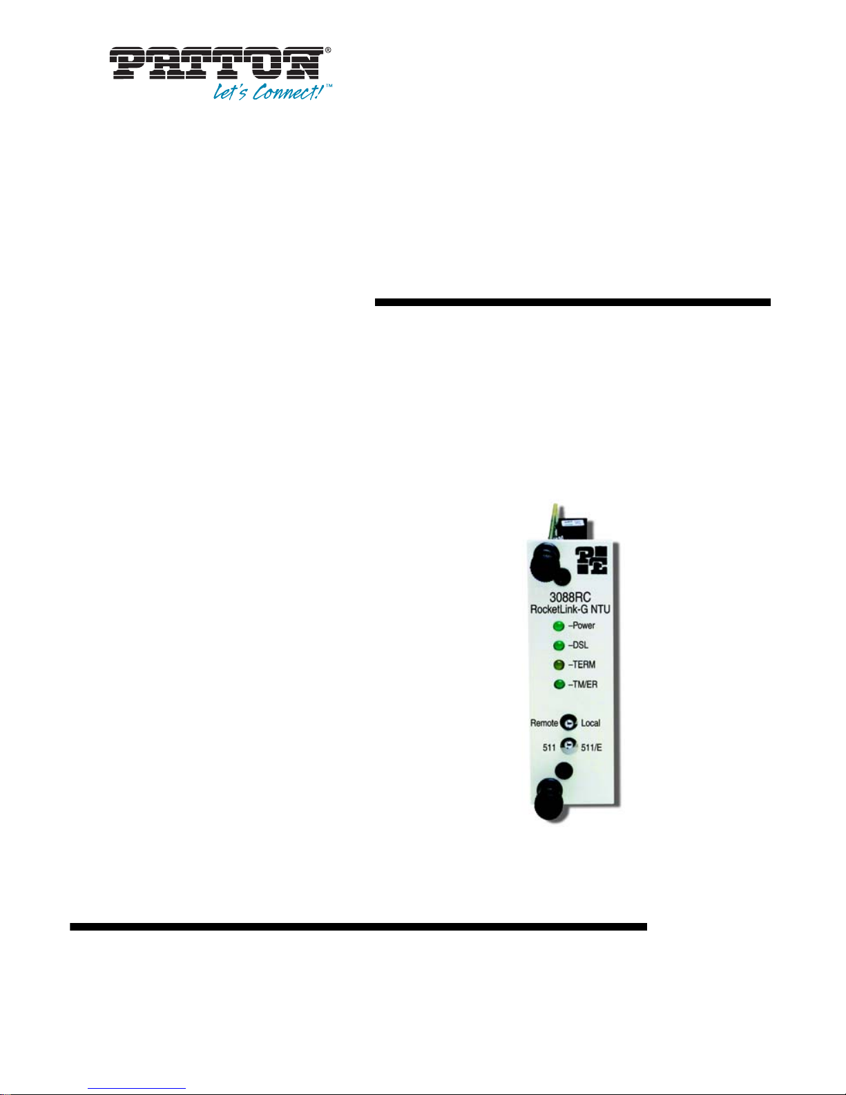
MODEL 3088RC
RocketLink-G NTU
Rack Mount G.SHDSL
Modem Card
SALES OFFICE
(301) 975-1000
TECHNICAL SUPPORT
(301) 975-1007
Part# 07M3088R C-UM, Rev. B
Revised 2/1 6/ 1 2
Page 2

2
1.0 Warranty Information ................................................................. 5
1.1 Compliance................................................................................... 5
EMC Compliance:.................... ...... ...... ..... .................................... 5
Low-Voltage Directive (Safety):........................... ......................... 5
PSTN Regulatory:......................................................................... 5
1.2 FCC Part 68 (ACTA) Statement ................................................... 6
1.3 Radio and TV Interference (FCC Part 15).................................... 6
1.4 Industry Canada Notice................................................................ 7
1.5 CE Declaration of Conformity....................................................... 7
1.6 Authorized European Representative........................................... 8
1.7 Service.......................................................................................... 8
1.8 Safety When Working With Electricity .......................................... 9
2.0 General Information.................................................................. 11
2.1 Features...................................................................................... 11
2.2 Description.................................................................................. 11
2.3 Serial Interface Types................................................................. 12
3.0 Configuration ............................................................................ 13
3.1 About Software (CLI) Configuration............................................ 13
3.2 About Harware (DIP Switch) Configuration ................................ 13
3.3 Configuring the DIP Switches (V.35, X.21, and Ethernet Models)...
14
S1-1 through S1-7: Data Rate.................................................... 15
S1-8: TX Clock ........................................................................... 17
S2-1: Front Panel Switches........................................................ 17
S2-2: Line Probe......................................................................... 17
S2-3: Annex A/B......................................................................... 17
S2-4 through S2-5: Clock Mode................................................. 18
X.21 operation. .................................................................... 18
Ethernet operation ............................................................... 18
S2-6: DTE Loops........................................................................ 19
S2-7: DTE Interface Type........................................................... 19
S3-1 through S3-8: Management Address................................. 19
3.4 About System Reset Mode......................................................... 19
Software Upgrades..................................................................... 20
Configuration Reset to Factory Defaults..................................... 20
3.5 Configuring through the Console................................................ 20
Console Help Commands........................................................... 22
System Configuration Commands.............................................. 23
System Status Commands......................................................... 24
DSL Configuration Commands................................................... 24
DSL Status Command................................................................ 25
DSL Clear Errcntrs Command.................. ...... ............................ 25
3.6 Configuring the V.35 Rear Card .......................... ...... ................. 26
Model 1001RCM13445 & 1001RCM134TB Strap Settings........ 26
DTE Shield (M/34 Pin A) & FRGND (JB3) .......................... 26
SGND & FRGND (JB4) ....................................................... 27
Page 3

3
3.7 Configuring the X.21 Rear Card .......................... ...... ................. 27
Model 1001RCM11545& 1001RCM115TB Strap Settings......... 27
DTE Shield (DB-15 Pin 1) & FRGND (JB3) ......................... 28
SGND & FRGND (JB4) ....................................................... 28
3.8 Configuring the E1 Rear Card .................................................... 28
DIP Switch Configuration............................................................ 28
Switch S1-1 : Line Coding .................................................. 28
Switch S1-2 : CRC-4 Multiframe ........................................ 29
Switch S1-3 : Clear Channel Mode .................................... 29
Switch S1-4 Through S1-8 : Reserved ................................ 29
Jumper Configuration................................................................. 29
Making Interface Connections.................................................... 30
Connect Twisted Pair (120 ohm) to G.703/G .7 04 Ne twork . 30
Connect Dual Coaxial Cable (75 ohm) to G.703/G.704 Net-
work. .................................................................................... 31
3.9 Connecting the Ethernet Rear Card ........................................... 32
Connecting the Interface Driver Board....................................... 33
Connecting to the 10Base-T Ethernet Port................................. 34
Connecting the 10Base-T Ethernet Port to a Hub ............... 35
Connecting the 10Base-T Ethernet Port to a PC (DTE) ...... 35
Connecting the Line Interface .............................................35
LED Status Monitors................................................................... 36
Status. ................................................................................. 37
Link. ..................................................................................... 37
3.10 Connecting the 10/100 Ethernet Rear Card............................... 38
Connecting the Interface Driver Board....................................... 39
Connecting to the 10/100BaseTX Ethernet Port........................ 40
Connecting the 10/100BaseTX Ethernet Port to a Hub ....... 41
Connecting the 10/100BaseTX Ethernet Port to a PC (DTE) ..
41
Connecting the Line Interface .............................................41
LED Status Monitors................................................................... 42
4.0 Installation................................................................................. 43
4.1 The Model 1001R14 rack chassis .............................................. 43
The Rack Power Supply............................................................. 43
Powering Up Your 1001R14 Rack.............................................. 44
4.2 Installing Model 3088RC series into the chassis........................ 44
4.3 Connecting the Twisted Pair Interface........................................ 45
4.4 Connecting the Model 3088RC/A/I (V.35) serial interface.......... 47
Connecting the Model 3088RC/A/I (V.35) to a “DTE” device..... 47
Connecting the Model 3088RC/A/I (V.35) to a “DCE” device..... 48
4.5 Connecting the Model 3088RC/D/V (X.21) serial interface ........ 49
Connecting the Model 3088RC/D/V (X.21) to a “DCE” or “DTE” de-
vice............................................................................................. 49
4.6 Connecting the 3088RC/K/K (E1) Interface................................ 50
4.7 Connecting the 3088RC/C/AI (Ethernet) Interface ..................... 50
Page 4

4
5.0 Operation................................................................................... 51
5.1 LED status indicators.................................................................. 51
5.2 Test Modes................................................................................. 52
Loopbacks.................................................................................. 52
Patterns...................................................................................... 53
5.3 Remote Console Operation........................................................ 53
Establishing a Remote Console Session.................................... 53
How to Connect ..................... .................................. ............ 53
How to Disconnect ...................... ..... ...... ..... ........................ 55
Differences in Local and Remote Control Session Behavior...... 56
5.4 Software Upgrade....................................................................... 57
5.5 Reset Configuration to Factory Default....................................... 58
A
Specifications ........................................................................... 59
A.1 Clocking modes .......................................................................... 59
A.2 DTE rate ...................................................................................... 59
A.3 Serial interface ............................................................................ 59
A.4 Serial connector .......................................................................... 59
A.5 Diagnostics ................................................................................. 59
A.6 Status LEDs ................................................................................ 59
A.7 Configuration .............................................................................. 60
A.8 Transmission line ........................................................................ 60
A.9 Line coding ................................................................................. 60
A.10 Line rates (DSL line) ................................................................... 60
A.11 Line interface .............................................................................. 60
A.12 G.SHDSL physical connection ................................................... 60
A.13 Environment ................................................................................ 60
B
Model 3088RC Interface Pin Assignments ............................. 61
B.1 RJ-11 non-shielded DSL port ..................................................... 61
B.2 V.35 interface .............................................................................. 61
B.3 E1 interface ................................................................................. 62
B.4 X.21 interface .............................................................................. 62
B.5 RS-232 console interface ........................................................... 63
B.6 Ethernet interface ....................................................................... 63
Page 5

5
1.0 WARRANTY INFORMATION
Patton Electronics warrants all Model 3088RC components to be free
from defects, and will—at our opti on —repair or replace the product
should it fail within one year from the first date of the shipment.
This warranty is lim ited to defect s in workman ship or mate rials, and do es
not cover customer damage, abuse or unauthorized modification. If this
product fails o r do es not p erforms as w arrante d, you r sole re cours e shal l
be repair or replacem ent as des cr ibed above. Under no conditio n shall
Patton Electronics be liable for any damages incurred by the use of this
product. These da mages incl ude, but are no t limited to, the foll owing: lost
profits, lost savings and incidental or consequential damages arising
from the use of or inability to use this product. Patton Electronics specifically disclaims all other warranties, expressed or implied, and the
installation or use of this product shall be deemed an acceptance of
these terms by the user.
1.1 COMPLIANCE
Note The compliance information in this document applies to Models
3088RC/C/IA and 3088RC/K/K only.
EMC Compliance:
• FCC Part 15, Class A
• EN55022, Class A
Low-Voltage Directive (Safety):
• UL 60950-1/CSA C22.2 N0. 60950-1 listed
• IEC/EN60950-1 2nd edition
• AS/NZS 60950-1
PSTN Regulatory:
• ACTA TIA/EIA/IS-968 A5
• This device is not intended nor approved for connection to the PSTN
Page 6

6
1.2 FCC PART 68 (ACTA) STATEMENT
This equipme nt complies with Part 68 of FCC rules an d the re quirement s
adopted by ACTA. On the bottom side of this equipment is a label that
contains—among other information—a product identifier in the format
US: AAAEQ##TXXXX. If requested, this number must be pro vided to the
telephon e company.
The method used to connect this equipment to the premises wiring and
telephone network must comply with the applicable FCC Part 68 rules
and requirements adopted by the ACTA.
If this equipment causes harm to the telephone network, the telephone
company will notify you in advance that temp orary di sc on tinuance of service may be required. But if advance notice isn’t practical, the telephone
company will notify the customer as soon as possible. Also, you will be
advised of your right to file a complaint with the FCC if you believe it is
necessary.
The telephone company may make changes in its facilities, equipment,
operations or procedures that could affect the operation of the equipment. If this hap pens the tel ephone co mpany will provi de advanc e notice
in order for you to make necessary modifications to maintain uninterrupted service.
If trouble is experienced with this equipment, fo r repair or warranty information, pleas e con tac t our co mp any. If the equipm ent is caus ing ha rm to
the telephone ne twork , the tel ephon e comp any may re quest that you di sconnect the equipment until the problem is resolved.
Connection to party line service is subject to state tariffs. Contact the
state public utility commission, public service commission or corporation
commission for information.
1.3 RADIO AND TV INTERFERENCE (FCC PART 15)
This device generates and uses radio frequency energy, and if not
installed and use d proper ly- that is, in s trict ac corda nce w ith the m anufa cturer’s instructions-may cause interference to radio and television reception. The de vi ce h as b een tested and fo und t o co mply wi th the lim its for a
Class A com puting devi ce i n accord ance with s pecifi catio ns in Subp art B
of Part 15 of FCC rules, which are de signed to provide reasonable protection from such interference in a commercial installation. However,
there is no gua ran tee that interference will not occur in a particula r in st a llation. If the device does cause interference to radio or television reception, which can be determined by disconnecting the unit, the user is
encouraged to try to corr ect the interf erence by on e o r more of the follow ing measures : m ov ing the c omp uti ng equipment away from the receive r,
re-orienting the receiving antenna and/or plugging the receiving equip-
Page 7

7
ment into a different AC outlet (such that the computing e quipment and
receiver are on different branches).
1.4 INDUSTRY CANADA NOTICE
This equipment meets the applicable Industry Canada Terminal Equipment Technical Specifications. This is confirmed by the registration number. The abbreviation, IC, before the registration number signifies that
registration was p erformed based on a Declaration of Conf orm ity ind ic ating that Industry Canada technical specifications were met. It does not
imply that Industry Canada approved the equipment.
This Declaration of Conformity means that the equipment meets certain
telecommunications network protective, operational and safety requirements. The Department does not guarantee the equipment will operate
to the user's satisfaction. Before installing this equipment, users should
ensure that it is permissible to be connected to the facilities of the local
telecommunications company. The equipment must also be installed
using an acceptable method of connection. In some cases, the company’s inside wiring associated with a single line individual service may
be extended by means of a certified connector assembly (telephone
extension cord). T he customer sh ould be awa re that compl iance wit h the
above condition may not prevent degradation of service in some situations. Repairs to some certified equipment should be made by an authorized maintenance facility designated by the supplier. Any repairs or
alterations made by the user to this equipment, or equipment malfunctions, may give the telecommunications company cause to request the
user to disconn ect the equipm ent. Use rs shou ld ens ure for the ir own pr otection that the ground connections of the power utility, telephone lines
and internal metallic water pipe system, are connected together. This
protection may be particularly important in rural areas.
1.5 CE DECLARATION OF CONFORMITY
We certify that the apparatus identified in this document conforms to the
requirement s of Council Directiv e 1999/5/EC on th e approxim ation of the
laws of the member states relating to Radio and Telecommunication Terminal Equipment and the mutual recognition of their conformity.
The safety adv ic e in the doc um entation accompanying this pro duc t s hal l
be obeyed. The conformity to the above directive is indicated by the CE
sign on the device.
Page 8

8
1.6 AUTHORIZED EUROPEAN REPRESENTATIVE
D R M Green
European Compliance Services Limited.
Oakdene House, Oak Road
Watchfield,
Swindon, Wilts SN6 8TD, UK
1.7 SERVICE
All warranty and no n-warranty repairs must be return ed freight prepaid
and insured to Patto n Elec tro nics. All returns must have a Return Materials Authorization number on the outside of the shipping container. This
number may be obtained from Patton Electronics Technical Services at:
•Tel: +1 (301) 975-1007
•Email: support@patton.com
• URL: http://www.patton.com
Note Packages received without an RMA number will not be
accepted.
Page 9
9
1.8 SAFETY WHEN WORKING WITH ELECTRICITY
• Do not open the device when the power cord is connected. For systems without a power switch and
without an external power adapter, line voltages
are present within the device when the power cord
is connected.
• For devices with an external power adapter, the
power adapter shall be a listed Limited Power
Source The mains outlet that is utilized to power
the device shall be within 10 feet (3 meters) of the
device, shall be easily accessible, and protected
by a circuit breaker in compliance with local regulatory requirements.
• For AC powered devices, ensure that the power
cable used meets all applicable standards for the
country in which it is to be installed.
• For AC powered devices which have 3 conductor
power plugs (L1, L2 & GND or Hot, Neutral &
Safety/Protective Ground), the wall outlet (or
socket) must have an earth ground.
• For DC powered devices, ensure that the interconnecting cables are rated for proper voltage, current, anticipated temperature, flammability, and
mechanical serviceability.
• WAN, LAN & PSTN ports (connections) may have
hazardous voltages present regardless of whether
the device is powered ON or OFF. PSTN relates to
interfaces such as telephone lines, FXS, FXO, DSL,
xDSL, T1, E1, ISDN, Voice, etc. These are known
as “hazardous network voltages” and to avoid
electric shock use caution when working near these
ports. When disconnecting cables for these ports,
detach the far end connection first.
• Do not work on the device or connect or disconnect
cables during periods of lightning activity.
WARNING
Page 10
10
This device contains no user serviceable parts. This device can
only be repaired by qualified service personnel.
This device is NOT intended nor approved for connection to the
PSTN. It is intended only for connection to customer premise
equipment.
Electrostatic Discharge (ESD) can damage equipment and impair
electrical circuitry. It occurs when electronic printed circuit cards
are improperly handled and can result in complete or intermittent
failures. Do the following to prevent ESD:
• Always follow ESD prevention procedures when removing and
replacing cards.
• Wear an ESD-preventive wrist strap, ensuring that it makes
good skin contact. Connect the clip to an unpainted surface of
the chassis frame to safely channel unwanted ESD voltages
to ground.
• To properly guard against ESD damage and shocks, the wrist
strap and cord must operate effectively. If no wrist strap is
available, ground yourself by touching the metal part of the
chassis.
In accordance with the requirements of council directive 2002/96/EC on Waste of Electrical and Electronic
Equipment (WEEE), ensure that at end-of-life you separate this product from other waste and scrap and deliver
to the WEEE collection system in your country for recycling.
WARNING
WARNING
CAUTION
Page 11

11
2.0 GENERAL INFORMATION
Thank you for your purchase of this Patton Electronics product. This
product has been thoroughly inspected and tested and is warranted for
One Year parts and labor. If any questions arise during in sta llation or use
of this product, please contac t Patton Electronics Technical Support at:
(301) 975-1007.
2.1 FEATURES
• Symmetrical high data rate DSL (G.SHDSL)
• Data rates up to 4.6Mbps in 64-kbps intervals
• Serial V.35 (DCE only) , X.21 (selectable DCE or DTE), Ethernet (RJ-
45), or T1/E1 interface
• RS-232 console port for manageme nt and configuration
• Built-in testing and diagnostics
• RocketLink Plug ‘n’ Play for easy installations
• Interoperable with other Patton G.SHDSL modems
•CE marked
2.2 DESCRIPTION
The Patton Electronics Model 3088RC G.SHDSL RocketLink provides
high speed 2-wire connectivity to ISPs, PTTs, and enterprise environments using Symmetrical High-data-rate Digital Subscriber Line
(G.SHDSL) technology.
As a symmetric DSL NTU, RocketLink DSL offers the same data rates in
both directions over a single pair of regular twisted pair lines u s ing TCP AM modu lation. Line co nnection is made with an RJ-45 ja ck. The Model
3088RC is designed to fit into Patton’s 2U (3.5”) high rack chassis. This
chassis uses a mid-plane architecture which allows front cards to be
plugged into d iffere nt rear c ards. For m ore informa tion, refe r to the Model
1001RP14 Manual for more inf ormation on th e power supp ly option s that
are available.
The NTU features exte rnally -acce ssibl e DIP switch es, lo opbac k diag no stics, SNMP/HTTP remote-management capabilities using RocketLink
Plug ‘n’ Play, as well as in-band management.
Page 12

12
2.3 SERIAL INTERFACE TYPES
The Model 3088RC versions listed below provide the following types of
built-in serial interfaces:
• 3088RC/A/I provides a V.35 interface on an M/34 female connector
• 3088RC/C/AI provides a Ethernet interface on an RJ45 connector
• 3088RC/D/V/V p rov ide s a X. 21 inte rfac e on a DB-15 female connector
• 3088RC/K/K prov ides a E1 interf ace on ei ther a n RJ48 -C con nector or
dual BNC
Page 13

13
3.0 CONFIGURATION
This section describes the location and orientation of the Model
3088RC’s configuration switches and jumpers, and provides detailed
instructions for all possible settings. Each 3088RC model has different
configuration requirements, depending on the card’s serial interface.
You can configure the 3088RC using either the software (CLI via a
1001CC port) or the hardware (via DIP switches).
3.1 ABOUT SOFTWARE (CLI) CONFIGURATION
To use software configuration you must set DIP switches S1 and S2 to
the ON position, and set DIP Switch S3 to the management address,
before powering-up the RocketLink-G. When DIP switches S1 and S2
are set to ON, the RocketLink-G will operate in software-configuration
mode. When set for software-configuration mode the RocketLink-G will
read any configuration data previously saved to FLASH memory during
system power-up. If no configuration data was previously saved to
FLASH, then the Rocket Lin k-G w il l loa d th e fac tory -de fau lt c onf igu r ati on
from FLASH memory. After power-up, you may use console commands
or the Embedd ed Operations Channel (EOC) to mo dif y the c on f igu rati on
parameters.
3.2 ABOUT HARWARE (DIP SWITCH) CONFIGURATION
To use DIP-switch configuration you must first set the DIP switches to a
position other than all OFF or all ON before powering-up the RocketLink-
G. When all the DIP switch es are se t to any po sitio n other than all OFF or
all ON the RocketLin k-G will ope rate in ha rdwa re (DIP-s witc h)-c onf igu ration mode. In DIP-switch-configuration mode the RocketLink-G will read
the DIP-switch setti ngs du rin g system st artup an d confi gure its elf ac cording to the switch settings.
Once you power-up the RocketLink-G in DIP-switch mode it will operate
in DIP-switch mode until powered down. When operating in DIP-switch
mode you cannot change any configuration settings:
• Changing the DIP switch settings while the device is running will not
modify the operating configuration because the RocketLink-G only
reads the DIP switches during s ystem startup.
• If you attempt to modify the configuration by issuing console commands, the dev ice wil l not e xecut e your c omma nds. Inste ad , the Roc ketLink-G will respond with a message indicating the device is
operating in DIP-switch-configuration mode.
Page 14
14
• If you atte mpt to mo dify any confi gu rati on parameters via the EOC (by
changing (EOC variables), the RocketLink-G will not execute your
changes.
3.3 CONFIGURING THE DIP SWITCHES
(V.35, X.21, and Ethernet
Models)
The Model 3088RC is equipped with three sets of DIP switches, which
you can use to configure the RocketLink-G for a broad range of applications. This section describes switch locations and discusses the configuration options available.
Note By default, the RocketLink-G’s DIP switches are all set to “ON”
so the NTU can be configured via the console. If that is how you
will be configuring the NTU, skip ahead to the section on configuring the console.. Otherwise, read the following sections to
manually configure the DIP switch settings.
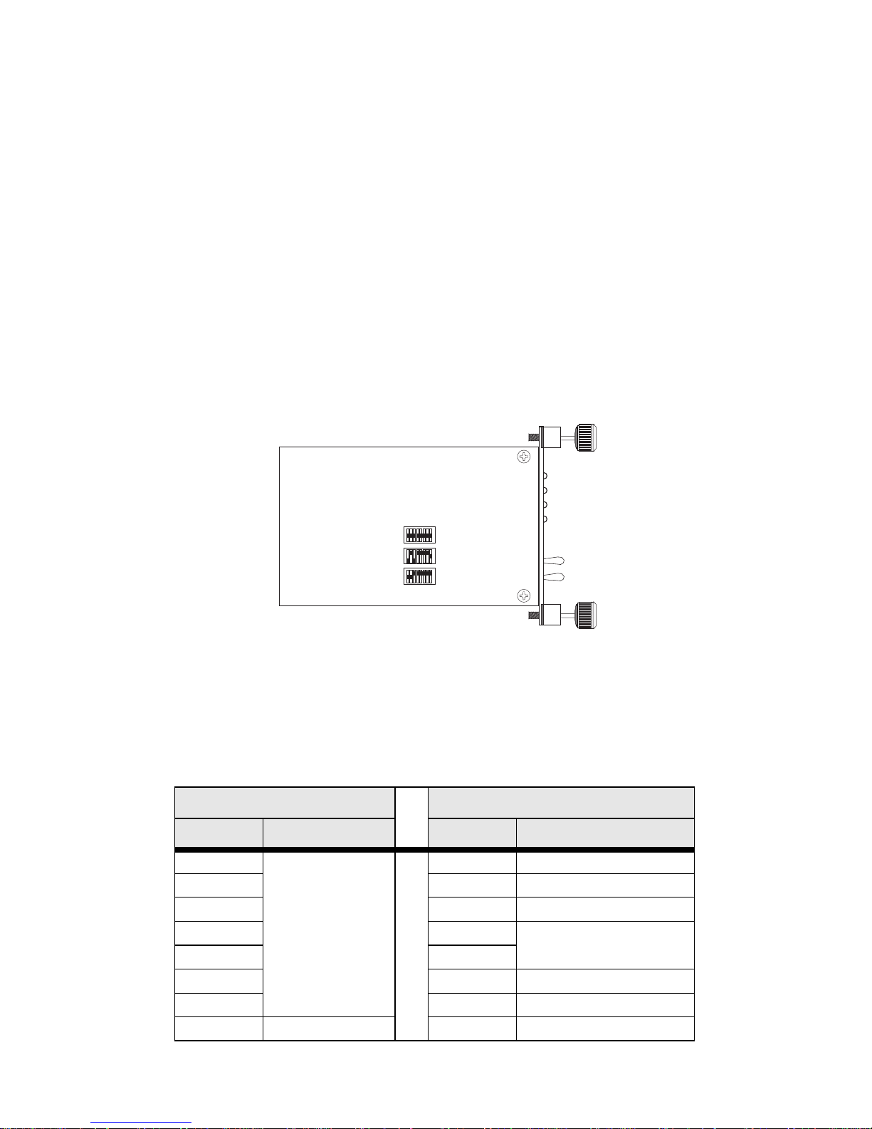
Figure 1. Location of DIP switches on Model 3088RC
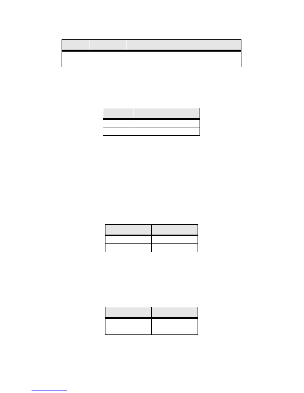
The three sets of DIP switches on the Model 3088RC are referred to as
S1, S2 and S3. DIP switch orientation with respect to ON and OFF positions is consistent for all switches.
The DIP switches S1 and S2 can be configured as either ON or OFF.
S1 S2
Position Function Position Function
S1-1 Data Rate S2-1 Front Panel Switches
S1-2 S2-2 Line Probe
S1-3 S2-3 Annex
S1-4 S2-4 Clock Mode
S1-5 S2-5
S1-6 S2-6 DTE Loops
S1-7 S2-7 DTE Interface Type
S1-8 TX Clock S2-8 Reserved
S1
S2
S3
Page 15

15
S1-1 through S1-7: Data Rate
Switches S1-1 throug h S1-7 def ine both the DSL data rate and the seri al
data rate.
S1-1 S1-2 S1-3 S1-4 S1-5 S1-6 S1-7
Data Rate
(kbps)
OFFONONONONONON64
ONOFFONONONONON128
OFF OFF ON ON ON ON ON 192
ONONOFFONONONON256
OFF ON OFF ON ON ON ON 320
ON OFF OFF ON ON ON ON 384
OFFOFFOFFONONONON448
ON ON ON OFF ON ON ON 512
OFF ON ON OFF ON ON ON 576
ON OFF ON OFF ON ON ON 640
OFF OFF ON OFF ON ON ON 704
ON ON OFF OFF ON ON ON 768
OFFONOFFOFFONONON832
ON OFF OFF OFF ON ON ON 896
OFF OFF OFF OFF ON ON ON 960
ON ON ON ON OFF ON ON 1024
OFFONONONOFFONON1088
ON OFF ON ON OFF ON ON 1152
OFF OFF ON ON OFF ON ON 1216
ON ON OFF ON OFF ON ON 1280
OFF ON OFF ON OFF ON ON 1344
ON OFF OFF ON OFF ON ON 1408
OFF OFF OFF ON OFF ON ON 1472
ON ON ON OFF OFF ON ON 1536
OFFONONOFFOFFONON1600
ON OFF ON OFF OFF ON ON 1664
OFF OFF ON OFF OFF ON ON 1728
ON ON OFF OFF OFF ON ON 1792
OFF ON OFF OFF OFF ON ON 1856
ON OFF OFF OFF OFF ON ON 1920
OFF OFF OFF OFF OFF ON ON 1984
ON ON ON ON ON OFF ON 2048
OFFONONONONOFFON2112
ONOFFONONONOFFON2176
Page 16

16
OFF OFF ON ON ON OFF ON 2240
ON ON OFF ON ON OFF ON 2304
OFF ON OFF ON ON OFF ON 2368
ON OFF OFF ON ON OFF ON 2432
OFF OFF OFF ON ON OFF ON 2496
ON ON ON OFF ON OFF ON 2560
OFF ON ON OFF ON OFF ON 2624
ON OFF ON OFF ON OFF ON 2688
OFF OFF ON OFF ON OFF ON 2752
ON ON OFF OFF ON OFF ON 2816
OFF ON OFF OFF ON OFF ON 2880
ON OFF OFF OFF ON OFF ON 2944
OFF OFF OFF OFF ON OFF ON 3008
ON ON ON ON OFF OFF ON 3072
OFFONONONOFFOFFON3136
ON OFF ON ON OFF OFF ON 3200
OFF OFF ON ON OFF OFF ON 3264
ON ON OFF ON OFF OFF ON 3328
OFF ON OFF ON OFF OFF ON 3392
ON OFF OFF ON OFF OFF ON 3456
OFF OFF OFF ON OFF OFF ON 3520
ON ON ON OFF OFF OFF ON 3584
OFF ON ON OFF OFF OFF ON 3648
ON OFF ON OFF OFF OFF ON 3712
OFF OFF ON OFF OFF OFF ON 3776
ON ON OFF OFF OFF OFF ON 3840
OFF ON OFF OFF OFF OFF ON 3904
ON OFF OFF OFF OFF OFF ON 3968
OFF OFF OFF OFF OFF OFF ON 4032
ON ON ON ON ON ON OFF 4096
OFFONONONONONOFF4160
ONOFFONONONONOFF4224
OFF OFF ON ON ON ON OFF 4288
ON ON OFF ON ON ON OFF 4352
OFF ON OFF ON ON ON OFF 4416
ON OFF OFF ON ON ON OFF 4480
OFFOFFOFFONONONOFF4544
ON ON ON OFF ON ON OFF 4608
S1-1 S1-2 S1-3 S1-4 S1-5 S1-6 S1-7
Data Rate
(kbps)
Page 17
17
S1-8: TX Clock
S2-1: Front Panel Switches
The 3088RC uses front panel switches to control test modes. They may
be disabled so that the 3088RC ignores them.
S2-2: Line Probe
Line probe is a mechanism that determines the highest rate (192K to
2304K) that the DSL link can reliab ly support. This takes place during
training. The DSL rate will be set to the rate that line probe determines.
Note that both the CO and CPE unit must have line probe enabled for it
to take effect.
Line probe co uld be us ed to determine the best rate the lin e will support,
and then the user could set the units for that rate and disable line probe
so that the rate won’t change without the us er’s knowle dge.
S2-3: Annex A/B
Annex A is typically used in North American-like networks, whereas
Annex B is typically used in European-like networks. The different
annexes specify different PSD (power spectral density) masks because
of the difference in T1 and E1 PSDs.
S1-8 Setting Description
ON Normal TD sampled on falling edge of TX clock.
OFF Inverted TD sampl ed on ris ing edge of TX clock .
S2-1 Front Panel Switches
ON Disabled
OFF Enabled
S2-2 Line Probe
ON Disabled
OFF Enabled
S2-3 Annex
ON A
OFF B
Page 18
18
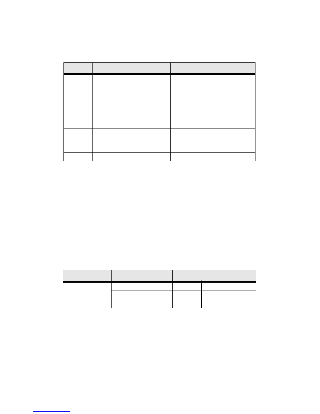
S2-4 through S2-5: Clock Mode
The RocketLink-G can operate in one of three clock modes: internal,
external, or receive-recover.
X.21 operation. There are a few things to note about clock modes and
X.21 operation.
— One X.21 modem must be set to Receive-Recover. The other
X.21 modem must be set to either Internal or External/Network
clock mode.
— The X.21 modem that is configured as Receive-Recover must
be DCE.
— The X.21 modem that is configured as Internal must also be
DCE, but if it is an External/Network clock, then the modem
must be configured as DTE.
Ethernet operation. The 3088RC/C/AI model does not recover clock
from the Ethernet network because it is packet-based rather than TDM.
Therefore, the external clock mode is not valid.
S2-4 S2-5 Clock Mode Description
ON ON Internal The on-board oscillator in
the 3088RC provides clock
for both serial and DSL
lines.
OFF ON External 3088RC uses the RX clock
from the serial interface as
the clock for the DSL link.
ON OFF Receive-
Recover
3088RC uses the RX cloc k
from the DSL line as the
clock for the serial interface .
OFF OFF Reserved
CPE-Side Modem CO-Side Modem
Modem’s X.21
Orientation
Receive-Recover Internal External/Network
DCE DCE x
DCE x DTE
Page 19
19
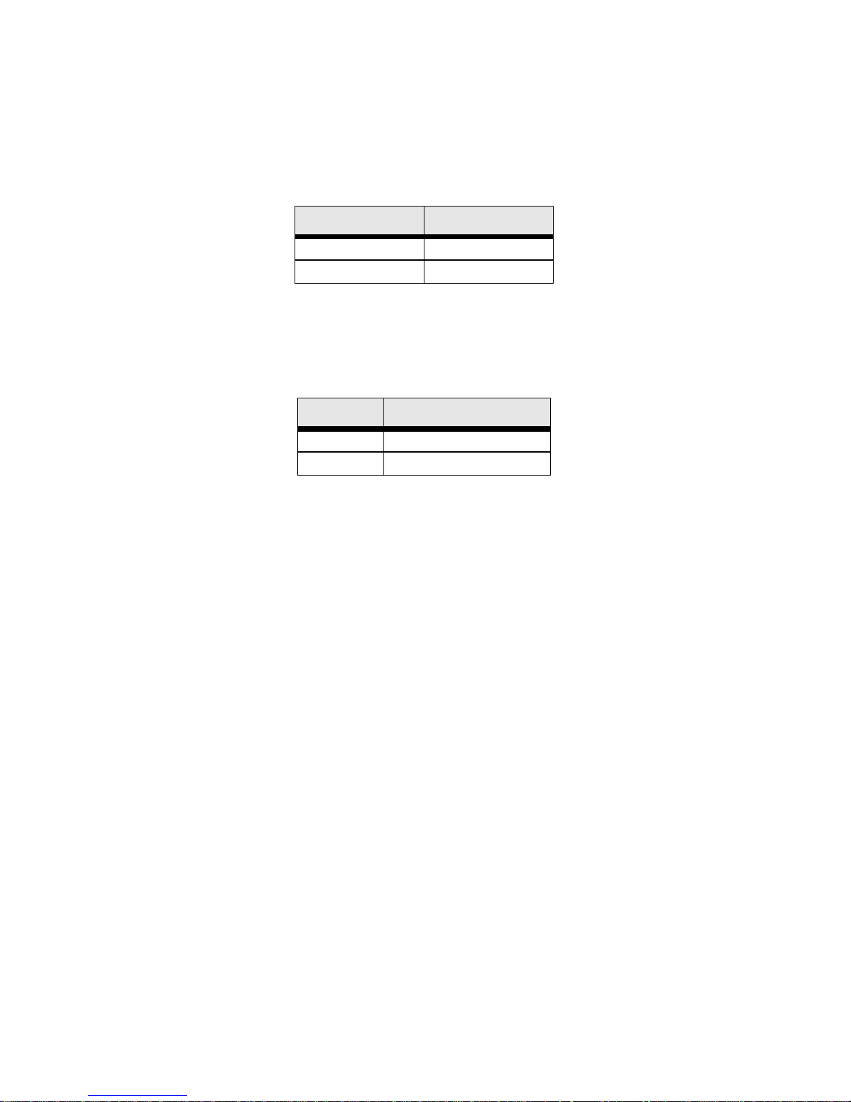
S2-6: DTE Loops
The V.35 interface provides two pins, one to request an LAL and the
other to request an RDL. If DTE loops are enabled, the 3088RC/A/I will
start a local loopback or a remote loopback when these pins are
asserted. If DTE loops are disabled, these requests will be ignored.
S2-7: DTE Interface Type
The DTE interface type nee ds to be set based on th e rear modul e. Set to
E1 if using the /K model. Set to normal if using any other model.
S3-1 through S3-8: Management Address
Each rack card in a chassis must have a unique management address.
The 1001CC and 1001MC use this address to activate and deactivate
the rack card's management interface. This is necessary because all
rack cards in a chassis communicate over the same bus, so only one
card can be active at a time.
This address can be set to any value between 0 and 255. Set S3 to the
binary representation of the number (ON=0 and OFF=1). S3-8 is the
most significant bit.
3.4 ABOUT SYSTEM RESET MODE
To enter system reset mode, switch all DIP switches to the OFF position
and power cycle the unit. You can use a VT100 emulator configured for
19200 bps/1 stop bit/ no parity/ XON-XOFF flow control to access the
console. Upon restart, you will see the message “Reset Mode”. The
3088RC automatically communicates through the 1001CC in reset
mode, and does not wait for its address.
System reset mode provides two functions: software upgrades and configuration reset to factory defaults.
S2-6 Setting
ON Enabled
OFF Disabled
S2-7 DTE Interface Type
ON E1
OFF Normal
Page 20

20
Software Upgrades
The softwa re is upgra ded by wait ing for the Res et Mode m essage. Then,
the user can send an Intel HEX file supplied by Patton. After the VT100
emulator has finished sending this file, the 3088RC will respond with a
mes-sage stating how many errors were detected. The user may then
set the DIP switches to the desired configuration and power cycle the
unit to run the upgraded software.
Configuration Reset to Factory Defaults
To recover from a forgotten password, the user may reset the unit to its
factory configuration. After se eing the Reset Mode message, the user
should type the ‘*’ key. This will result in a ‘:’ prompt. At the prompt, the
user should ent er the co mman d reset. This wil l restore the uni t to the fa ctory configuration. The unit can then be restarted with the settings in
place.
3.5 CONFIGURING THROUGH THE CONSOLE
The 3088RC offers a console command line interface. To access the
console, use a VT100 emulator configured to 9600 bps, 1 stop bit, no
parity, and XON-XOFF flow control. Use the 1001CC to access the console. Type CTRL+B <address> <enter> to activate the console. Log into
the unit using the default password. No username will be needed.
Note Log in with the default password superuser.
You can configure the following variables through the console:
• Password: The password used to login to the console.
• Circuit ID: The circuit ID communicated to other units via EOC. EOC
(Embedded Operations Channel) is an out-of-band channel specified
in the G.991.2 standard for SHDSL. We use standard EOC messages
for our remote loopback. The 3088RC also supports proprietary EOC
messages that allow a 3096RC to configure it.
• Clock Mode: The following options are available:
— Internal: The internal oscillator in the 3088RC provid es the
clock to both the serial/T1/E1 and DSL interfaces.
— External: The serial interface provides the clock for the DSL
interface (V.35, X.21). It must be set to DTE for the X.21 interface. (This mode is invalid for the Ethernet model).
— Receive Recover: The 3088RC recovers the clock from the
DSL interface and provides it to the serial/E1 interface.
Page 21

21
• Data Rate: Both the seria l/E1 and DSL dat a rates ar e set by sp ecifying
the number of 64k timeslots.
• Annex: Either G.991.2 Annex A or Annex B.
• DTE Interface Type: Either E1 or a normal serial interface.
• DSL Error Monitor Max Interval Errors: The number of errors
allowed in an interval before considering the interval errored. A value
of ‘0’ disables the DSL error monitor.
• DSL Error Monitor Interval Time: The length in seconds of
an interval.
• DSL Error Monitor Interval Count: The number of errored intervals
allowed before restarting the DSL link.
• DSL Error Monitor Total Intervals: The number of i ntervals to insp ect
before disabling the error monitor.
• DSL Error Monitor Startup Delay: The length in seco nds t o wa it af ter
the DSL link is established before starting the error monitor.
• Test Modes: Loopbacks (LAL or RDL) and PRBS (pseudo-random
binary sequence) BER tests (511 or 511 with errors)
• Line Probe: Enable or disable Line Probe for rate
adaptive applications.
The following status information is available through the command
line interface:
• LEDs: Which software controlled LEDs are currently on.
• FPSW Settings: What the fro nt p a nel switches are set to (if the unit is
populated with them).
• Configuration Mode: Whether the 3088RC is configured by DIP
switches or software.
• DSL Link State: In Progress, Success, Deactivated, or Idle.
• DSL Sync State: Out of Sync, Acquiring Sync, In Sync, or Losing
Sync.
Note DSL Link State vs. DSL Sync State—The DSL link state
describes whether the DSL is training (in progress), linked (success), deactivated (we don’t have an option to deactivate the
modem, so the user should not see this), or idle.
The DSL sync state describes whether no sync words have
Page 22

22
been found (out of sync), there are no sync word errors (in
sync), or whether we are transitioning from out of sync to in sync
(acquiring sync) or vice versa (losing sync). Typically, when the
link is training, the sync state goes from out of sync to acquiring
sync to in sync.
• DSL Actual Rate: The actual rate at which the DSL link is running
(minus DSL overhead).
• DSL Line Condition: Good or Poor.
• Noise Margin Ratio: the maximum tolerable increase in external
noise power that still allows for BER of less than 1x 10⁻⁷.
• DSL Error Counters: The following error counters are available:
— CRC
— LOSW (Loss of Sync Word)
— TX FIFO Full
— TX FIFO Empty
— TX FIFO Slip
—TX Stuff
— RX FIFO Full
— RX FIFO Empty
— RX FIFO Slip
Console Help Commands
The following commands are provided to help the user find the
correct command:
• help: Lists all the commands that the console recognizes.
• system help: Lists all the commands that start with system that the
console recognizes.
• system set help: Lists all the commands that start with system set
that the console recogn iz es.
• system show help: Lists all the commands that start with system
show that the console recognizes.
Page 23

23
• dsl help: Lists all the commands that start with dsl that the
console recognizes.
• dsl set help: Lists all the commands that start with dsl set that the
console recognizes.
• dsl show help: Lists all the commands that start with dsl show that
the console recognizes.
• dsl show errcntr help: Lists all the commands that start with dsl
show errcntr that the console recognizes.
System Configuration Commands
The following commands allow the user to configure the system:
• system set password <password>: Set s the sy ste m p assword.
• system set circuitid <circuitid>: Sets the circuit ID.
• system set clockmode <internal|external|receiverecover>: Sets
the clock mode. Internal clock mode means the 3088RC provides the
clock to both the DSL and the serial interface. External clock mode
means the 3088RC uses the serial transmit clock as its DSL transmit
clock. Receive recover clock mode means that the 3088RC uses the
DSL receive clock as its DSL transmit clock and as the serial receive
clock.
Note X.21 External Clock Mode—The X.21 interface expects the
DCE to provide the clock used for both transmitting data and for
sampling receive data. When the 3088RC/D/V is set as a DCE,
it may be used in internal or receive recover clock modes. The
DSL generates a clock that is provided to the X.21 interface.
When the 3088RC/D/V is a DTE, it may be used in external
clock mode. The X.21 interface needs to provide the clock. This
clock is used by the DSL to sample the serial data and also to
update the receive data.
The 3088RC is set for either DCE or DTE by flipping the daughter-card. The 3088RC is a DCE if DCE points toward the front of
the 3088RC.
• system set dteif <normal|e1>: Set to E1 if the rear card is Model
3088RC/K/K. Set to normal for all other models.
• system set fpsw <enabled|disabled>: Enable or disable initiating
test modes using the front panel switches.
Page 24

24
The following commands allow the user to view the current
system configuration:
• system show config: Shows the configuration of the entire system,
including DSL and serial/T1/E1 lines.
Any changes to the sys tem config uration or the DSL co nfiguratio n will be
lost on the next power cycle unless the changes are saved. The command system save config is used to save the changes.
System Status Commands
The following commands show system status:
• system show status: Shows the following system status information:
LEDs, DSL test mode, front panel switch settings, DSL link state, and
configurati on mo de.
DSL Configuration Commands
The following commands are used to configure the DSL:
• dsl set timeslots <1–72>: Sets the number of timeslots. The data rate
is calcul ated by the equation: data-rate = #timeslots x 64k.
• dsl set annex <a|b>: Set the annex.
• dsl set lineprobe <enabled|disabled>: Enable or disable line probe.
• dsl set link <enabled|disabled>: Enable or disable the DSL port.
When disabled, a DSL link cannot be established.
• dsl set loopback <off|lal|rdl>: Start or stop loopbacks.
• dsl set pattern <off|511|511e>: Start or stop PRBS generator and
BER meter.
• DSL Error Monitor
The DSL error monitor i nspect s interva ls to see if the y have met the error
threshold (maxint). If the error monitor finds a certain number (intcnt) of
intervals that meet or exceed the error threshold, it will restart the DSL
link. The error monitor will wait (startdelay) seconds after the DSL link
comes up before it b egins mo nitoring erro rs. After th e startu p delay, it will
Startup Delay Interval 1 Interval 2 …
Interval
totint
?startdelay⇒ ?inttime
⇒
?inttime
⇒
?inttime
⇒
?inttime
⇒
Page 25

25
check the number of errors that hav e occurred during each (inttime) seconds to see if they meet the error threshold. The error monitor inspects
(totint) intervals before it stops.
Note Setting maxint to 0 disables the error monitor and setting totint
to 0 causes the error monitor to run continuously.
The following commands configure the error monitor:
• dsl set errmon maxint <maxint>: Sets the number of errors al lowed
in an interval causes it to be considered an errored interval. If this is
set to ‘0’, then the error monitor is disabled.
• dsl set errmon inttime <inttime>: Sets the length of each interval.
• dsl set errmon intcnt <intcnt>: Sets the number of errored intervals
that causes the DSL link to restart.
• dsl set errmon totint <totint>: Set s the number of intervals to ins pect
for errors before di sabli ng the er ror moni tor. If this is set to ‘0’, then the
error monitor will run continuously.
• dsl set errmon startdelay <startdelay>: Sets the number of sec onds
to wait after the DSL link comes up before the error monitor starts
inspecting intervals.
Changing the d at a rate (dsl set timeslots), the clock mode (system set
clockmode), the Annex (dsl set annex), or Line Probe (dsl set
lineprobe), or the DSL error monitor settings will not take effect on the
DSL link until the link restarts. The dsl start command restarts the
DSL link.
DSL Status Command
The dsl show status command shows the following DSL stat us inform a-
tion: link stat e, sync sta te, link speed, error co unters, l ine con dition , noise
margin, and test mode status.
DSL Clear Errcntrs Command
The dsl clear errcntrs command clears the error counte r s.
Page 26

26
3.6 CONFIGURING THE V.35 REAR CARD
The V.35 interface card is configured by setting the configuration straps
and dip switches located on the PC board.
Model 1001RCM13445 & 1001RCM134TB Strap Settings
Figure 2 shows the strap location for the Model 1001RCM134XX (M/34)
rear card. This strap determines whether Signal Ground and Frame
Ground will be connected.
Figure 2. 1001RCM134XX strap locations
The table below pro vi des an ov erv iew of interface strap functions for the
rear interface cards. Following the table overview are detailed descriptions of each strap’s function.
* Indicates default setting
DTE Shield (M/34 Pin A) & FRGND (JB3). In the connected position,
this strap links M/34 pin A & frame ground. In the open position, pin A is
disconnected from frame ground.
Strap Function Position 1&2 Position 2&3
JB3 DTE Shield (Pin A) & FRGND Connected Open*
JB4 FRG ND & SGND (Pin B) Connected Open*
JB3 Description
Position 1&2 DTE Shield (Pin A) and FRGND Connected
Position 2&3 DTE Shield (Pin A) and FRGND Not Connected
123
123
JB3
JB4
Page 27

27
SGND & FRGND (JB4). In the conne cted pos ition, th is strap links Signal
Ground and frame ground through a 100 ohm resistor. In the open position, signal ground is disconnected from frame ground.
3.7 CONFIGURING THE X.21 REAR CARD
The X.21 interface card is configured by setting the configuration straps
located on the PC board.
Model 1001RCM11545& 1001RCM115TB Strap Settings
Figure 3 shows strap locations for the Model 1001RCM115XX (DB-15)
rear cards. Thes e st ra p s det erm ine va rio us grou nd ing characteristics for
the terminal interface and twisted pair lines. JB3 and JB4 are user configurable.
Figure 3. 1001RCM115XX strap locations
The table below pro vi des an ov erv iew of interface strap functions for the
rear interface cards. Following the table overview are detailed descriptions of each strap’s function.
* Indicates default setting
JB4 Description
Position 1&2 SGND and FRGND Connected
Position 2&3 SGND and FRGND Not Connected
Strap Function Position 1&2 Position 2&3
JB3 DTE Shield (Pin1) & FRGND Connected Open*
JB4 FRGND & SGND (Pin 8) Connected Open*
123
JB3
JB4
123
Page 28

28
DTE Shield (DB-15 Pin 1) & FRGND (JB3). In the connected position,
this strap links DB-15 pin 1 & frame ground . In the open position, pi n 1 is
disconnected from frame ground.
SGND & FRGND (JB4). In the connecte d position, th is strap link s DB-15
pin 8 (Signal Ground) and frame ground through a 100 ohm resistor. In
the open position, pin 8 is connected directly to frame ground.
3.8 CONFIGURING THE E1 REAR CARD
The E1 rear card features co nfigura tion capabi lit y via hard ware swi tches
and jumpers. Sec tions 4.1 and 4.2 de sc rib e al l sw it ch a nd ju mp er co nfi g urations for the 3088RC/K model. Section 4.3 describes the configuration required for your mDSL modem.
DIP Switch Configuration
The E1 card has eight internal DIP switches (S1-1 through S1-8). The
DIP switches can be configured as either “On” or “Off.”
Switch S1-1 : Line Coding. Use Switch S1-1 to control the Network
Line Coding options. Set these options to be the same as the Line Coding that has been provided by your Service Provider.
Line Coding Options:
• High Density Bipolar 3 (HDB3): In HDB3 coding, the transm itt er
deliberately inserts a bipolar violation when excessive zeros in the
data stream ar e detected. The receiver reco gni zes these special violations and dec odes th em as zeros . This method enabl es the net work to
meet minimum pulse density requirements. Use HDB3 unless AMI is
required in your application .
JB3 Description
Position 1&2 DTE Shield (Pin 1) and FRGND Connected
Position 2&3 DTE Shield (Pin 1) and FRGND Not Connected
JB4 Description
Position 1&2 SGND (Pin 8) and FRGND Connected through a 100-ohm resistor
Position 2&3 SGND (Pin 8) and FRGND Directly Connected
S1-1 Line Framing & Coding
Off HDB3
On AMI
Page 29

29
• Alternate Mark Inversion (AMI): AMI coding does not inherently
account for ones dens ity . To meet thi s requirement, you should ensure
that the data inherently meets pulse density requirements.
Switch S1-2 : CRC-4 Multiframe. CRC-4 Multiframe uses Time Slot
zero to carry CRC-4 information. When CRC-4 is enabled (ON), the u nit
synchronizes to the CRC-4 multi-frame protocol.
Note When the data rate is set to 2048 Kbps, K Module transmits
user data on all 32 timeslots, ignoring framing information. In
this case, Switch S1-2 will be ignored.
Switch S1-3 : Clear Channel Mode. When S1-3 is at Off position, the
K Module is running in G.703 clear channel mode. When S1-3 is at On
position, the K Module is running in G.704 framed mode. When the K
Module is set to framed mode, channel 0 will be used to pass G.704
framing information which results in a maximum bandwidth of 1984kbps
for user data.
Switch S1-4 Through S1-8 : Reserved. Reserved for future use and
should be set to OFF.
Jumper Configuration
The 3088RC/K mode l has four jumper s (two position he aders): JP4, JP5,
JP6, and JP7. These jump ers are used to selec t input and output impedance matching between the module and external line. See Appendix E
for jumper locations.
The following is a description of the jumper settings with respect to the
front panel connectors.
1. For a 75 ohm connection (coax) install JP4 - JP7 (default).
2. For a 120 ohm connection (RJ-48C) remove JP4 - JP7.
S1-2 Option
Off On
Disabled Enabled
S1-3 Option
Off On
Clear Channel Mode (G.703) Framed Mode
(G.704)
Page 30

30
Making Interface Connections
The 3088RC/K model may be connected to G.703/G.704 ports using a
single 120 ohm RJ-48C or a dual 75 ohm coax (BNC). The 3088RC/K
model rear panels and the location of these connectors are show below.
Figure 4. K Module Rear Panels, Showing Location of Connectors
Connect Twisted Pair (120 ohm) to G.703/G.704 Network . The
3088RC/K model is equipped with a single RJ-48C jack for connections
to a 120 ohm twisted pair G.703/G.704 network interface. If your G.703/
G.704 network terminates via RJ-48 C , use the diagram belo w and the
table on the following page to make the proper connections. The connector pinout and signals are shown in Figure 5.
Use the following connection diagram to connect the 120 ohm G.703/
G.704 network channel.
Figure 5. 120 ohm RJ-48C G.703/G.704 Interface
Page 31

31
Connect Dual Coaxial Cable (75 ohm) to G.703/G.704 Network. The
3088RC/K model is also equipped with dual female BNCs (TX and RX)
for connection to a 75 ohm dual coax G.703/G.704 network interface. If
your G.703/G.704 network terminates via dual coaxial cable, use the diagram below to make the proper connections. The connector pinout and
signals are shown in Figure 6.
Figure 6. 75 ohm Dual Coaxial G.703 Interfac e
Note The outer conductor of the coax cables are isolated
from system earth ground.
Page 32

32
3.9 CONNECTING THE ETHERNET REAR CARD
The Model 3088RC/C/AI module plugs into Patton’s1092ARC and
3088RC modem s to pro vide Et hernet L AN ex tensio n. The 3 088RC /C/AI
has no switches or jumpers and does not need to be configured. However, factors such as the type of med iu m, th rou ghp ut across the lin k an d
clocking mode must be determined by the settings of the baseband
modems. Please refer to yo ur baseba nd modem (i.e. 109 2, and 109 5) to
make the following settings.
1. Bit Rate: The DTE rate setting of y our bas e unit c orresp onds to the
throughput of your 3088RC/C/AI bridge module. Use higher speeds
to allow maximum throughput to your extended LAN. Use lower
speeds to limit the access of your extended LAN.
Note The 3088RC/C/AI only supports synchronous speeds.
2. Clocking Mode: Set the clocking modes on the base units so that
one unit is c onfigured for Internal clocki ng mode and the oth er unit is
set for Receive Recover clocking mode.
3. When using the 3088RC/C/AI, DISABLE, the “Enable Loop from
DTE” Switch on the front function card (1092ARC or 3088RC).
4. All other base unit s ettings depe nd up on yo ur app licat ion an d on the
application medium (twisted pair or coaxial cable)
Page 33

33
Connecting the Interface Driver Board
This package co nta ins an interfa ce driv er board that al lows y ou to co nfi gure your front function card for ethernet operation. Figure 7 shows the
Interface Driver Board connected to a Model 3088RC front function card.
Figure 7. Driver Board mounted on Model 3088RC
Follow the instruc t ion s be low to con nec t the inte rfac e dri ver b oard to the
front function card:
1. With the function card (such as 30 88RC, shown above) pull ed out of
the NetLink rack or clus terb ox cha ssis , loc ate the dri ver board to be
replaced on the top of the base unit front card.
2. Lift the old interface board gently off of the printed circuit board.
3. Position the 3088RC/C/AI driver board on top of the function card’s
pc board with the sockets oriented toward the male pins. Please be
sure the label marked FRONT is pointed toward the front of the
function card (toward the LEDs).
4. Push the In terfa ce Driver Board gent ly o nto the socket a nd re -ins t a ll
the function card into the rack or cluster system.
Page 34

34
Connecting to the 10Base-T Ethernet Port
The Model 3088RC/C/AI provides line side connections through a terminal block or through a RJ-45 connector. Figure 8 below, shows the rear
panel options and the locations of the connectors.
Figure 8. 3088RC/C/AI Ethernet Port
The RJ-45 Ethernet port on Model 3088RC/C/AI is designed to connect
directly to a 10BaseT network. Figure 9 shows the 10BaseT RJ-45 port
pin description. You may make connections up to 33 0 feet us ing Type 4
or 5 cable .
Figure 9. Model 3088RC Ethernet Connector Pinout
Page 35

35
Connecting the 10Base-T Ethernet Port to a Hub . The Model
3088RC/C/AI 10Base-T interface is configured as DTE (Data Terminal
Equipment), just like a 10Base-T network interface card in a PC. Therefore, it “expects” to connect to a 10Base-T Hub using a straight-through
RJ-45 cable. Use th e diagram below to construct a cable to co nne ct t he
3088RC/C/AI to a 10Base-T Hub.
Connecting the 10Base-T Ethernet Port to a PC (DTE). The Model
3088RC/C/AI 10Base-T interface is configured as DTE (Data Terminal
Equipment). If you wish to connect the 3088RC/C/AI to another DTE
device such as a 10Base-T network interface card in a PC, you must
construct a 10Base-T crossover cable as shown in the diagram below.
Connecting the Line Interface. The Model 3088RC/C/AI is to be used
with Patton function card access products (i.e. 1092ARC) There are two
essential requirements for connecting th e line interface on Model
3088RC/C/AI:
1. These units work in pairs with one 3088RC/C/AI connected to
another 3088RC/C/AI (or IM1/I) over 2 or 4-Wire Twisted pair (2 or
4-Wire operation is determined by the front function card).
2. To function properly, the Model 3088RC/C/AI needs one or two
twisted pairs of metallic wire (two or four wire). The twisted pairs
must be unconditioned, dry, metallic wire, between 19 (.9mm) and
26 AWG (.4mm) (Ap pendix B describe s cabl e require ments ) . Standard dial-up telephone circuits, or leased circuits that run through
Page 36

36
signal equalization equipment, or standard, flat modular telephone
type cable, are not acceptable.
Figure 10. RJ-45 Line Interface
Note T wo-Wire Modems use RJ-45 pins 4 and 5 and 4-Wire Modems
use RJ-45 pins 3, 4, 5 and 6, as shown above. Please see the
Function Card User Manual for more details.
LED Status Monitors
The Model 3088RC/ C/AI feature s two LEDs that moni tor general operating status and the 10Base-T twisted pair link integrity. Figure 11 shows
the LEDs located directly beneath the RJ-45 jack.
Figure 11. 3088RC Rear Panel, LED Locations
Page 37

37
Status. Blinks yellow from one to ele ven times to indicate system stat us.
Each pulse pattern is separated by a 2 second “off” period. Greater
pulse patterns have higher priority (buffer saturation has greater priority
than an empty MAC table). Valid system st atus es are:
• 1 pulse = system status ok
• 2 pulses = No MAC entries in the MAC address table
• 3 pulses = Clear to send (CTS) or Carrier Detect (DCD) from base unit
are not asserted
• 4 pulses = IMRC2/IA buffer is saturated
• 5 pulses = WAN receive frame(s) too large
• 6 pulses = WAN receive frame(s) not Octet aligned
• 7 pulses = WAN receive frame(s) aborted
• 8 pulses = Detected WAN receive frame(s) with bad CRC
• 9 pulses = Detected LAN receive frame(s) too large
• 10 pulses = Detected LAN receive frame(s) not Octet aligned
• 11 pulses = Detected LAN receive frame(s) with bad CRC
After a statu s c od e is dis pl aye d ei ght times and the associated condition
is removed, the status code will no longer appear.
Link. Glows green to indicate good link integrity on the 10Base-T
twisted pair line.
Page 38

38
3.10 CONNECTING THE 10/100 ETHERNET REAR CARD
The Model 3088RC/C/AI-100B module plugs into Patton’s 3088RC
modem to provide Eth ernet LAN exten sion. The 3 088RC/C/AI-10 0B has
a jumper that needs to be configu red. The jump er at J7 shoul d be factor y
installed on pins 1 and 2. Factors such as the type of medium, throughput across the link and clocking mode must be determined by the settings of the 3088 standalone modem. Please refer to your 3088
standalone modem to make the following settings.
1. Bit Rate: The DTE rate setting of y our bas e unit c orresp onds to the
throughput of your 3088RC/C/AI-100B bridge module. Use higher
speeds to allow maximum throughput to your extended LAN. Use
lower speeds to limit the access of your extended LAN.
Note The 3088RC/C/AI-100B only supports synchronous speeds.
2. Clocking Mode: Set the clocking modes on the base units so that
one unit is c onfigured for Internal clocki ng mode and the oth er unit is
set for Receive Recover clocking mode.
3. When using the 3088RC/C/AI-100B, DISABLE, the “Enable Loop
from DTE” Switch on the front function card.
4. All other base unit s ettings depe nd up on yo ur app licat ion an d on the
application medium (twisted pair).
Page 39

39
Connecting the Interface Driver Board
This package co nta ins an interfa ce driv er board that al lows y ou to co nfi gure your front function card for ethernet operation. Figure 12 shows the
Interface Driver Board connected to a Model 3088RC front function card.
Figure 12. Driver Board mounted on Model 3088RC
Follow the instruc t ion s be low to con nec t the inte rfac e dri ver b oard to the
front function card:
1. With the function card pulled out of the NetLink rack or clusterbox
chassis, locate the driver board to be replaced on the top of the
base unit front card.
2. Lift the old interface board gently off of the printed circuit board.
3. Position the 3088RC/C/AI-100B driver board on top of the function
card’s pc board with the sockets oriented toward the male pins.
Please be sure the label marked FRONT is pointe d towa rd the front
of the function card (toward the LEDs).
4. Push the In terfa ce Driver Board gent ly o nto the socket a nd re -ins t a ll
the function card into the rack or cluster system.
Page 40

40
Connecting to the 10/100BaseTX Ethernet Port
The Model 3088RC/C/AI-100B provides line side connections through a
terminal bloc k or th rough a RJ-45 conne ctor. Figure 13 below, show s the
rear panel options and the locations of the connectors.
Figure 13. 3088RC/C/AI-100B Ethernet Port
The RJ-45 Ethernet port on Model 3088RC/C/AI-100B is designed to
connect directly to a 10/100BaseTX network. Figure 14 shows the 10/
100BaseTX RJ-45 port pin description. Y ou may make connections up to
330 feet using CAT5 cable.
Figure 14. Model 3088RC Ethernet Connector Pinout
Page 41

41
Connecting the 10/100BaseTX Ethernet Port to a Hub. The Model
3088RC/C/AI-100B 10/100BaseTX interface is auto-sensing, meaning
that it can connect to eith er a 10/1 00 BaseTX switch, hub or a PC. Use a
straight-through or cross-over cable to connect the 10/100BaseTX port.
Refer to the wiring diagram below.
Connecting the Line Interface. The Model 3088RC/C/AI-100B is to be
used with Patton function card access products.There are two essential
requirements for connecting the line interface on Model 3088RC/C/AI100B:
1. These unit s work in p ai rs w i th o ne 3 088 R C/ C/AI-10 0B c onn ec ted to
another 3088RC/C/AI-100B (or 3088/I standalone modem) over 2wire twisted pair.
2. To function properly, the Model 3088RC/C/AI-100B needs one
twisted pair of metallic wire (two wire). The twisted pairs must be
unconditione d, dry, metallic wire, between 19 (.9mm) and 26 AWG
(.4mm) (Appendix B describes cable requirements). Standard dialup telephone circuits, or leased circuits that run through signal
equalization equipment, or standard, flat modular telephone type
cable, are not accept ab le.
Figure 15. RJ-45 Line InterfaceTwo-Wire Modems use RJ-45 pins 4 and 5 and 4-Wire
Modems use RJ-45 pins 3, 4, 5 and 6, as shown above. Please see the Function Card User
Manual for more details.
Page 42

42
LED Status Monitors
The Model 3088RC/C/IA-100B features two LEDs that monitor general
operating status and the 10/100BaseTX twisted pair link integrity.
Figure 16 shows the LEDs located directly beneath the RJ-45 jack.
Figure 16. 3088RC/C/IA-100B Rear Panel, LED Locations
Activity LED
Yellow
Link LED
Green
Page 43

43
4.0 INSTALLATION
This section d escrib es the fu nctio ns of the Mo del 100 1R14 rack chas sis,
tells how to install front and rear Model 3088RC Series cards into the
chassis, and how to connect to the twisted pair interface and the serial
interface.
4.1 THE MODEL 1001R14 RACK CHASSIS
The Model 1001R14 Rack Chassis (Figure 17) has fourteen short range
modem card slots, plus its own power supply. Measuring only 3.5” high,
the Model 1001R14 is designed to occupy only 2U in a 19” rack. Sturdy
front handles allow the Model 1001R14 to be extracted and transported
conveniently.
Figure 17. Model 1001R14 Rack Chassis with power supply
The Rack Power Supply
The power supply included in the Model 1001R14 rack uses the same
mid-plane archit ec ture as the modem cards . The fron t card of the powe r
supply slides in from the front, and the rear card slides in from the rear.
They plug into one another in the middle of the rack. The front card is
then secured by thumb screws and the rear card by conventional metal
screws.
There are no user-serviceable parts in the power supply
section of the Model 3088RC Series. Voltage setting
changes and fuse replacement should only be performed by qualified service personnel. Contact Patton
Electronics Technical support at (301) 975-1007 for
more information.
WARNING
Page 44

44
Powering Up Your 1001R14 Rack
Note The power supplies that come with your 1001R14 rack system
are equipped with a power entry connector on the rear card. The
power supplies are Hot-Swappable, so you are not required to
remove the cards from the rack while applying power to the system.
When a power cabl e is connected between the unit, and an appropriate
power source, a green LED on the front panel will glow to indicate that
the unit is working properly. Since the Model 1001R14 is a "hot swappable" rack, it is not neces sary for an y cards to be inst alled before app lying
power. The power may be removed at any time without harming the
installed cards.
Note Please refer to the Model 1001RP14 Series User Manual AC &
DC Rack Mount Power Supplies for fuse and power card
replacement information.
4.2 INSTALLING MODEL 3088RC SERIES INTO THE CHASSIS
The Model 3088RC Series is comprised of a front card and a rear card.
The two cards meet inside the rack chassis and plug into each other by
way of mating 50 pin card edge connecto rs. Us e the foll owing ste ps as a
guideline for installing each Model 3088RC Series into the rack chassis:
1. Slide the rear card into the back of the chassis along the metal rails
provided.
2. Secure the rear card using the metal screws provided.
3. Slide the front card into the front of the chassis. It should meet the
rear card when it’s almost all the way into the chassis.
4. Push the front card gently into the card-edge receptacle of the rear
card. It should “click” into place.
5. Secure the front card using the thumb screws.
Page 45

45
4.3 CONNECTING THE TWISTED PAIR INTERFACE
The Model 3088RC supports communication between two DTE devices
as follows:
Using 24 AWG (0.5 mm) wire up to:
• 32,000 feet (9.7 km) at 192 kbps
• 18,500 feet (5.6 km) at 2.312 Mbps
Using 26 AWG (0.4 mm) wire up to:
• 23,000 feet (7 km) at 192 kbps
• 13,200 feet (4 km) at 2.312 Mbps
Two things are essential:
1. These units work in pairs. Both units at the end of the twisted pair
DSL span must be set for the same DTE rate—one unit set as CO,
the other as CP.
2. To function properly, the Model 3088RC needs one twisted pair of
metallic wire. This twisted pair must be unconditioned, dry, metallic
wire, between 19 (0.9mm) an d 26 AWG (0.4m m) (the higher number
gauges will limit distance). Standard dial-up telephone circuits, or
leased circuits that run through signal equalization equipment, or
standard, flat modular telephone type cable, are not acceptable.
The interconnecting cables shall be acceptable for
external use and shall be rated for the proper application with respect to voltage, current, anticipated temperature, flammability, and mechanical serviceability.
CAUTION
Page 46

46
The RJ-45 connector on the Model 3088RC’s twisted pair interface is
polarity insensitive and is wired for a two-wire interface. The signal/pin
relationships are shown in Figure 18.
Figure 18. Model 3088RC V.35/X.21 interfaces
3088RC/D/V
(X.21, female DB-15)
3088RC/A/I
(V.35, female DB-25
)
Page 47

47
4.4 CONNECTING THE MODEL 3088RC/A/I (V.35) SERIAL INTER-
FACE
Model 3088RC/A/I supports V.35 serial port connections. This section
describes how to connect the serial ports to your V.35 equipment.
Connecting the Model 3088RC/A/I (V.35) to a “DTE” device
The Model 3088RC/A/I provides a V.35 DCE (data circuit terminating
equipment) interface on a M/34 connector. As a DCE, this interface is
designed to co nnect to DTE equipment, su ch as a ro ute r. When connecting the V.35 interfac e of t he Model 3088RC/ A/I to you r DTE dev ice, us e a
V.35 straight-through cable. Appendix B.2 on page 61 describes pin
assignments and signal sources for the Model 3088RC/A/I V.35 interface.
Figure 19. Connecting the Model 3088RC/A/I to V.35 Serial DTE
The interconnecting cables shall be acceptable for
external use and shall be rated for the proper application with respect to voltage, current, anticipated temperature, flammability, and mechanical serviceability.
CAUTION
Straight-Through Cable
DSL Span
3088RC (DCE)
Remote G.SHDSL NTU
V.35 Router (DTE)
3088RC
RocketLink-G NTU
–Power
–DSL
–TERM
–TM/ER
Remote Local
511 511/E
3088RC
RocketLink-G NTU
–Power
–DSL
–TERM
–TM/ER
Remote Local
511 511/E
Page 48

48
Connecting the Model 3088RC/A/I (V.35) to a “DCE” device
The Model 3088RC/A/I provides a V.35 DCE (data circuit terminating
equipment) interface on a M/34 connector. As a DCE, this interface is
designed to connect to DTE equipment, such as a router. However, connecting the 3088RC/A/I to another DCE device, such as a multiplexer or
G.703 E1 NTU, requires a tailcircuit cable. When connecting the V.35
interface of the Model 3088RC/A/I to your DCE device, use a V.35 tail
circuit cable . Som e ap pli ca tio ns m ay al so require the installation of a t ai lcircuit buf fer to ac cou nt fo r sm al l differences in clock frequency betwe en
the 3088RC/A/I and the V.35 DCE (multiplexer).
Figure 20. Connecting the Model 3088RC/A/I to V.35 Serial DCE
Tail-circuit cable
DSL Span
Model 3088RC/A (DCE)
Remote Model 3088RC
(DCE)
G.703 E1 NTU
3088RC
RocketLink-G NTU
–Power
–DSL
–TERM
–TM/ER
Remote Local
511 511/E
3088RC
RocketLink-G NTU
–Power
–DSL
–TERM
–TM/ER
Remote Local
511 511/E
Page 49

49
4.5 CONNECTING THE MODEL 3088RC/D/V (X.21) SERIAL INTER-
FACE
Model 3088RC/D/V supports X.21 serial port connectio ns. This section
describes how to connect the serial ports to your X.21 equipment.
Connecting the Model 3088RC/D/V (X.21) to a “DCE” or “DTE”
device
The Model 3088RC/D/V provides an X.21 interface on a DB-15 female
connector . The X.21 interface default conf iguration is DCE for connectio n
to DTE (data terminal equipment) such as a router. However, the X.21
interface on the Model 3088 R C/D /V m ay be c onf igu r ed as DTE (data terminal equipment) for connection to DCE such as a modem or multiplexer. When connecting the X.21 interface of th e Model 3088RC/D/V to
your DTE or DCE device, use an X.21 straight-through cable.
Figure 21. Connecting the Model 3088RC/D/V to X.21 DTE or DCE
The DCE/DTE s trap is loca ted on the dau ghter b oar d. The a rrows on the
top of the strap indi cate th e confi guratio n of the X.21 port (f or example , if
the DCE arrows are pointing toward the front of the rack card, the unit is
configured as a DCE). Similarly, if the DTE arrows are pointing toward
the front of the rack card, the unit is configured as a DTE.
The interconnecting cables shall be acceptable for
external use and shall be rated for the proper application with respect to voltage, current, anticipated temperature, flammability, and mechanical serviceability.
CAUTION
Straight-Through 15-pin
D-Sub Cable
Model 3088RC/D (DCE or DTE)
DSL Span
Remote Model 3088RC
Router (DTE)
OR
Mux (DCE)
3088RC
RocketLink-G NTU
–Power
–DSL
–TERM
–TM/ER
Remote Local
511 511/E
3088RC
RocketLink-G NTU
–Power
–DSL
–TERM
–TM/ER
Remote Local
511 511/E
Page 50

50
4.6 CONNECTING THE 3088RC/K/K (E1) INTERFACE
The Model 3088RC/K/K is a rear-mountable G.703/G.704 interface card
that works with the Patton Model 3088RC function card. The two cards
meet inside the rack chassis and plug into each other by way of mating
50 pin card edge connectors. Use the following steps as a guideline for
installing each Model 3088RC/K/K and its function card mate into the
rack chassis:
1. Slide the rear card into the back of the chassis along the metal rails
provided.
2. Secure the rear card using the metal screws provided.
3. Slide the front card into the front of the chassis. It should meet the
rear card when it’s almost all the way into the chassis.
4. Push the front card gently into the card-edge receptacle of the rear
card. It should “click” into place.
5. Secure the front card using the thumb screws.
4.7 CONNECTING THE 3088RC/C/AI (ETHERNET) INTERFACE
The Model 3088RC/C/AI is a rear-moun table ethernet interface card.
The two cards meet inside the rack chassis and plug into each other by
way of matin g 50 pin ca rd edge con nectors. Us e the follo wing st eps as a
guideline for installing each Model 3088RC/C/AI and its function card
mate into the rack chassis:
1. Slide the 3088RC/C/AI rear card into the back of the chassis al ong
the metal rails provided.
2. Secure the 3088RC/C/AI rear card using the metal screws provided.
3. Slide the front function card into the front of the chassis. It should
meet the 3088RC/C/AI rear card when it is almost all the way into
the chassis.
4. Push the front card gently into the card-edge receptacle of the rear
card. It should “click” into place.
5. Secure the front card using the thumb screws.
Page 51

51
5.0 OPERATION
Once the Model 3088RC is properly configured and installed, it should
operate transparently. These sections describes functions of the LED
status indicators, and the use of the built-in loopback test modes.
5.1 LED STATUS INDICATORS
The Model 3088RC features four front panel LEDs that monitor the operation of the rack card. Figure 22 shows the front panel location of each LED.
Table 1 describes each LED’s function.
Figure 22. The Model 3088RC Series’ front panel LEDs
Table 1: Model 3088RC front panel LED descriptiont
LED Color Description
Power Green Flashing = POST
Solid = Power is on
DSL Green Flashing = Training
Solid = DSL Link
TERM Yellow Solid = Serial port is active
TM/ER Green Solid = Test mode is active
Blinking = Test mode error
3088RC
RocketLink-G NTU
–Power
–DSL
–TERM
–TM/ER
Remote Local
511 511/E
Page 52

52
5.2 TEST MODES
The 3088RC offers test modes in the form of loopbacks, PRBS pattern
generators, and combinations of bo th (see Figure 22 on page 51).
Figure 23 is a block diagram of the Model 3088RC with respect to test
modes.
Figure 23. 3088RC Block Diagram
Loopbacks
The 3088RC supports both Local Analog Loopbacks (LAL) and Remote
Digital Loopbacks (RDL). These can be initiated either from the optional
front panel switches or by the console command dsl set loopback
<off|lal | rdl>. The data path for the LAL is shown in Figure 24.
Figure 24. Local Analog Loopback Diagram
The data received from the serial interface is looped back before going
out on the DSL line. Note that this loopback occurs after the pattern generator/BER meter. This means that running a 511 pattern in conjunction
with an LAL should result in no error detected by the meter. The data
path for the RDL is shown in Figure 25.
Figure 25. Remote Digital Loopback Diagram
The RDL causes the remote unit to loop the data received from the DSL
line back to the DSL line.
DSL
Framer
511 Pattern
Generator
511 BER
Meter
DSL
Framer
511 Pattern
Generator
511 BER
Meter
Line
DSL
Framer
511 Pattern
Generator
511 BER
Meter
DSL
Framer
511 Pattern
Generator
511 BER
Meter
Line
DSL
Framer
511 Pattern
Generator
511 BER
Meter
DSL
Framer
511 Pattern
Generator
511 BER
Meter
Line
Page 53

53
Patterns
The 3088RC can generate and detect 511 and 511 with Error patterns.
These can be initiated either by the optional front panel switches or by
the console command dsl set pattern <off|511|511e>. When the pattern
is started, the DSL framer uses its internal 511 pattern generator for its
DSL TX data instead of the data received from the serial interface. Also,
the framer’s internal BER Meter tries to detect a 511 pattern in the DSL
RX Data.
Because the BER Meter always runs when the pattern generator runs,
the meter will detect errors if either the pattern is not either looped back
or the remote unit is not transmitting a 511 pattern.
One point to n ote is that t he way errors are g enerated in the 511E pattern
generates CRC errors. This can cause the DSL error monitor to restart
the link if the thresholds are set low enough.
5.3 REMOTE CONSOLE OPERATION
The PC user (near-end) may configure and verify status of the remote
3088RC (far-end) via a Remote Console session. The PC user must log
onto the 3088RC (near-end) unit to establish a remote console session.
Once done, the remote 3088RC (far-end) appears as a unit which is
locally connected through the RS-232 console port. All commands are
transmitted over the G.SHDSL link in the EOC channel.
Figure 26. Remote control session Diagram
Establishing a Remote Console Session
How to Connect . The following steps are to establish a connection to
the remote 3088RC (far-end) via Remote Console Session (RCS):
1. Configure a terminal em ulatio n prog ram ( e.g. , Hype rtermin al) on PC
(near-end) for 9600 bps, 8 data bits, no parity, 1 stop bit, no flow
control. Connect it to the 1001CC in the same chassis as the
3088RC (near-end).
2. At the password prompt, log in to the near-end Model 3088RC.
RS-232
Remote Console Session (RCS)
DSL
PC
(Near End)
3088
(Near End)
3088
(Far End)
Page 54

54
3. Ensure that a DSL link is established. You can verify an established
DSL link by using the system show status command or by checking
that the DSL LED is solid green. Upon executing the show status
command, the dsl link state is shown as success if the DSL link is
established.
4. At the command prompt, enter the command remote console.
5. Wait for the message Console: Remote console connection estab-
lished.
— If a DS L link is not established, or for some other reason the
3088RC (far-end) does not respond in a reasonable amount of
time, the foll owing messa ge appears: C onsole: Rem ote consol e
timed out trying to con-nect. Enter the command remote console again.
— If 3088RC (Far End) already has an active remote console ses-
sion open, you will see the message Console: Remote console
connection request rejected. This ca n also hap pen if the re mote
3088RC (far-end) has an established remote console session
with the local 3088RC (near-end) which has timed out.
6. Enter the password at the password prompt for the remote console
session.
Note The passwords for a local console session of the 3088RC (near-
end) and the remote console session of the 3088RC (far-end)
should be different for the purpose of security.
7. You should now be l ogg ed into th e rem ot e 3 088RC (far-end) vi a th e
remote console session. The communication with the remote
3088RC (far-end) is essentially the same as having a local console
connection.
Note The local or remote 3088RC may be CO or CPE, as long as
there is one of each. Either the CO or CPE unit may accept a
remote console connection.
Note With a remote console session open, a user at PC (far-end) is
blocked from using the local console. Upon typing anything, the
3088RC (far-end) sends a message to the PC (far-end) stating
Console: Remote console connection is open.
Page 55

55
Figure 27 is a screenshot of opening a typical remote console session:
Figure 27. Opening a typical remote console session
How to Disconnect . The remote console session ends under any of
the following conditions:
• The user enters the command logout
• A timeout period of 5 minutes elapses since the user has entered a
command to the console.
• The DSL link drops.
The response upon logging out of the remote console session with the
command logout is Console: Remote console connection lost. The fol-
lowing is what is di splayed u pon a user’s logg ing out of a remote conso le
session after loggi ng in.
> remote console
>
Console: Remote console connection established.
password: ******
> logout
Console: Remote console connection lost.
Log in to 3088RC (Near End)
system show status command
shows that DSL link is not up
remote console command requests a
remote console session on 3088RC (Far End)
Message informs us that the 3088RC (Far End) did not
respond and a remote
console session was not opened
system show status command shows
that the DSL link state is success
remote console command requests a
remote console session on 3088RC (Far End)
Message informs us that we are now
connected to the 3088RC (Far End) console
We can now enter commands on
the remote console
Page 56

56
>
The timeout peri od is a fix ed, non-c onfigurabl e par ameter of 5 minutes . If
the remote 3088RC (far-end) has received no command within 5 minutes, it automatically terminates the RCS. Once the RCS is terminated,
the PC (far-end) can establish a local console session if desired. However if the PC (near-e nd) wishes to re-est ab lish a R CS, it is a ble to d o so
whether or not the PC (far-end) is in an activ e local sessio n, because the
RCS has priority over a local console session. If the PC (near-end)
establishes an RCS while the PC (far-end) is on a local session, the PC
(far-end) is kicked off.
Differences in Local and Remote Control Session Behavior
Since the remote console session communication occurs over the
G.SHDSL link’s EOC channel, some commands via the RCS have
unusual effects.
• system upgrade: Do not issue this command via an RCS. A system
upgrade must be done via the local console connection. If you should
accidentally issue this command over an RCS, the remote 3088RC
(far-end) waits indefinitely for input (which is the system upgrade
image) from the local co nsole port of the 3 088RC (far-e nd). If this command is entered, 3088RC (Far End) will have to be power-cycled.
Figure 28. Remote control session with LAL diagram
Do not attempt a software upgrade of the remote unit
over the Remote Control Session.
CAUTION
PC
(Near End)
RS-232
Remote Console Session (RCS)
DSL
RS-232
LAL
3088
(Near End)
3088
(Far End)
PC
(Far End)
Page 57

57
• dsl set loopback lal: Do not iss ue this c omm an d ov er th e R CS to the
far-end 3088RC. If the far-end goes into LAL, the near-end and farend 3088RC NTUs can no longer communicate over the RCS.
5.4 SOFTWARE UPGRADE
The Model 3088RC is software upgradeable through the console port.
Software images will be available in Intel Hex file fo rmat.
The software upgrade feature is available either by powering up the
Model 3088RC with all DIP switch es set to the OFF position, or by enter-
ing the system upgrade command on the command line interface. The
software upgrade takes approximately 5 minutes to complete. The
3088RC will print ‘.’ to the screen while the software upgrade is in process. When the software upgrade completes, it will print a message stating that it is complete and the number of errors, if any, that occurred.
Errors may occur dur ing the sof tware upgrade if the i mage i s corrupt o r if
there is a disruption in the console port connection. The Model 3088RC
will print a mess age to the console port if it encounters any errors . In t he
event of an error, the portions of the old image may have been overwritten, and the unit may not be able to boot into operational mode. However, the unit may still boot in to the software upgrade, so a new software
image can still be loaded to bring the unit back to an operational state.
Here is the software upgrade procedure:
1. Remove all cards fro m the rack except f or the card th at you in tend to
upgrade.
2. Obtain the software image Hex file for the 3088RC.
3. Turn off the Model 3088RC.
4. Make a note of the current DIP switch settings, then set all DIP
switches to the OFF position.
5. Turn on the Model 3088RC.
6. Configure HyperTerminal for 19200 bps, 8 bits, 1 stop bit, no parity,
XON-XOFF.
Do not issue this command to a far-end unit. If you were
to do so, the near-end 3088RC would no longer be able
to communicate with the far-end 3088RC.
CAUTION
Page 58

58
7. Open Model 30 88RC Console (via HyperTerminal or other terminal
emulation program).
>>Transfer
>>Send Text File...
>>Set “Files of Type:” to “All files (*.*)”
>>Select 033252Z.hex
8. When the transfer completes, turn off the Model 3088RC.
9. Set the DIP switches for the proper configuration.
10.Turn on the Model 3088RC. It now operates with the upgraded software.
5.5 RESET CONFIGURATION TO FACTORY DEFAULT
The configuratio n can be reset to fa ctory defaul ts from the software res et
mode. This allows a user to recover from a forgotten password. To reset
to the configuration, follow these steps:
1. Power down the unit.
2. Set all DIP switches to the OFF position.
3. Connect a PC to the Console port.
4. Open a VT100 terminal emulator (such as HyperTerminal). Configure the emulator for 19200 bps,1 stop bit, no parity, X-ON X-OFF
flow control.
Note The 3088RC will not wait for its address to be selected when in
software reset mode. It will automatically accept data from the
1001CC.
5. Power up the unit. The terminal should display the following message: Reset Mode.
6. Type the ‘*’ key. You will see a ‘:’ prompt.
7. Type the command reset.
8. When the command completes, the unit has been reset to factory
configuration.
9. Set the DIP switches to the desired configuration. Power cycle the
unit to begin using the new config urat ion.
Page 59

59
APPENDIX A
S PECIFICATIONS
A.1 CLOCKING MODES
Internal, external (V.35 only), or receive recovered
A.2 DTE RATE
All 64k steps from 64 to 4608 kbps
A.3 SERIAL INTERFACE
V.35 (Model 3088RC/A/I), DCE orientation;
X.21 (Model 3088RC/D/V), DCE or DTE orientation depending on orien-
tation of daughter board mounted on the mother board.
E1 (Model 3088RC/ K/K) present s G.703/G.704 interface. Eith er 75 Ohms
(unbalanced) or 120 Ohms (bal anced). Pins 1 & 2 are Receive. Pins 4 &
5 are Transmit.
A.4 SERIAL CONNECTOR
D-Sub-25 Female (Model 3088RC/A/I)
D-Sub-15 Female (Model 3088RC/D/V)
Dual BNC and RJ48C (Model 3088RC/K/K), strap selectable
A.5 DIAGNOSTICS
V.52 compliant (511/511E) pattern generator and detector with error
injection mode controlled by front-panel switch. Local and Remote Loopback control either by a front-panel switch or from the DTE interface.
A.6 STATUS LEDS
• Power (Green): The Power LED glows solid during normal operation.
At startup, during the POST, the LED blinks once every second.
• DSL (Green): The DSL LED glows solid when a DSL link is estab-
lished. While the DSL link is training, it blinks once every second.
• Term (Yellow): The Term LED glows solid when a serial port is active.
• TM/ER (Green): The Test Mode/Error ( TM/ER) LED i s used to indicat e
that a test mode is in progress or an error has been detected. It blinks
once every second while a test mode is starting. It glows solid while a
Page 60

60
test mode is in progress. It blinks once if an error is detected either
during a test mode , or in normal DSL operation.
A.7 CONFIGURATION
Configuration is do ne with eith er extern ally ac cess ible DIP switc hes, CLI
or through the EOC (Embedded Operations Channel) from a Model
3096RC G.SHDSL concentration card.
A.8 TRANSMISSION LINE
Single Twisted Pair
A.9 LINE CODING
TC-PAM (Trellis Coded Pulse Amplitude Modulation)
A.10 LINE RATES (DSL LINE)
All nx64 rates from 64 kbps up to 4.6 Mbps
A.11 LINE INTERFACE
Transformer coupled, 2500 VRMS isolation
A.12 G.SHDSL PHYSICAL CONNECTION
RJ-45, 2-wire polarity insensitive pins 4 and 5
A.13 ENVIRONMENT
Operating temp: 32–122°F (0–50°C)
Humidity: 5–95% non-condensing
Altitude: 0–15,000 feet (0–4,600 meters)
Page 61

61
APPENDIX B
MODEL 3088RC INTERFACE PIN ASSIGNMENTS
B.1 RJ-11 NON-SHIELDED DSL PORT
Single twisted-pair (TP) for full-duplex transmission. The signals are
polarity insensitive.
B.2 V.35 INTERFACE
(M/34F Female Connec tor: DCE Confi guration)
Pin # Signal
1
2Tip
3Ring
4
Pin # Signal
B SGND (Signal Ground)
C RTS (Request to Send)
D CTS (Clear to Send)
E DSR (Data Set Ready)
F CD (Carrier Detect)
H DTR (Data Terminal Ready)
L LLB (Local Line Loop)
M TM (Test Mode)
N RDL (Remote Digital Loop)
P TD (Transmit Data)
R RD (Receive Data)
S TD/ (Transmit Data-B)
T RD/ (Receive Data-B)
U XTC (External Transmit Clock)
V RC (Receive Timing)
W XTC/ (External Transmit
Clock)
X RC/ (Receive Timing)
Y TC (Transmit Clock-A)
AA TC/ (Transmit Clock-B)
Page 62

62
B.3 E1 INTERFACE
RJ-48C female connec tor
B.4 X.21 INTERFACE
D-sub-15 female connector (DTE/DCE orientation)
Pin # Signal
1 Receive (Ring)
2 Receive (Tip)
3Shield
4 Transmit (Ring)
5 Transmit (Tip)
6Shield
7 No conne ction
8 No conne ction
Pin # Signal
1 Frame Ground
2 T - Tran smit Dat a-A (DTE Source)
3 C - Control-A (DTE Source)
4 R - Receive Data-A (DCE Source)
5 I - Indication-A (DCE Source)
6 S - Signal Element Timing-A (DCE Source)
7 BT - Byte Timing-A (DCE Source)
8 SGND - Signal Ground
9 T/ - Transmit Data-B (DTE Source)
10 C/ - Control-B (DTE Source)
11 R/ - Receive Data-B (DCE Source)
12 I/ Indication-B (DCE Source)
13 S/ Signal Elemen t Timing-B (DCE Source)
14 BT/ - Byte Timing-B (DCE Source)
Page 63

63
B.5 RS-232 CONSOLE INTERFACE
RJ-45 non-shielded connector (EIA-561)
B.6 ETHERNET INTERFACE
RJ-45 non-shielde d conn ec tor
Pin # Signal
1DSR (out)
2 CD (out)
3DTR (in)
4 Signal Ground
5 RD (out)
6TD (in)
7 CTS (out)
8RTS (in)
Pin # Signal
1TD+
2TD3 RD+
4 No conne ction
5 No conne ction
6 RD7 No conne ction
8 No conne ction
Page 64

64
NOTES
_______________________________________________________
_______________________________________________________
_______________________________________________________
_______________________________________________________
_______________________________________________________
_______________________________________________________
_______________________________________________________
_______________________________________________________
_______________________________________________________
_______________________________________________________
_______________________________________________________
_______________________________________________________
_______________________________________________________
_______________________________________________________
_______________________________________________________
_______________________________________________________
© Copyright 2012.
Patton Electronics Company
All Rights Reserved
 Loading...