

Patton PX405PED Owner's Manual
WA R RA NT Y I N FO R M AT IO N
T RO UB LE SH OO TI NG
F RE QU EN TLY AS KE D Q U ES T I ON S
PLEASE READ AND SAVE THESE IMPORTANT INSTRUCTIONS
Owner’s Guide
PX405PED
WA R RA NT Y I N FO R M AT IO N
Pedestal Fan
153638/9100010012591 PX405PED_11EM1 Printed In China
GCDS-PAT22434-PH
10 YE AR LIMITE D WARRAN TY
Sunbeam Products, Inc. doing business as Jarden Consumer Solutions or if in Canada, Sunbeam Corporation (Canada)
Limited doing business as Jarden Consumer Solutions (collectively “JCS”) warrants that for a period of ten years from
the date of purchase, this product will be free from defects in material and workmanship. JCS, at its option, will repair
or replace this product or any component of the product found to be defective during the warranty period.
Replacement will be made with a new or remanufactured product or component. If the product is no longer available,
replacement may be made with a similar product of equal or greater value. This is your exclusive warranty. Do NOT
attempt to repair or adjust any electrical or mechanical functions on this product. Doing so will void this warranty.
This warranty is valid for the original retail purchaser from the date of initial retail purchase and is not transferable.
Keep the original sales receipt. Proof of purchase is required to obtain warranty performance. JCS dealers, service
centers, or retail stores selling JCS products do not have the right to alter, modify or any way change the terms and
conditions of this warranty.
This warranty does not cover normal wear of parts or damage resulting from any of the following: negligent use or
misuse of the product, use on improper voltage or current, use contrary to the operating instructions, disassembly,
repair or alteration by anyone other than JCS or an authorized JCS service center. Further, the warranty does not
cover: Acts of God, such as fire, flood, hurricanes and tornadoes.
What are the limits on JCS’s Liability?
JCS shall not be liable for any incidental or consequential damages caused by the breach of any express, implied or
statutory warranty or condition.
Except to the extent prohibited by applicable law, any implied warranty or condition of merchantability or fitness for a
particular purpose is limited in duration to the duration of the above warranty.
JCS disclaims all other warranties, conditions or representations, express, implied, statutory or otherwise.
JCS shall not be liable for any damages of any kind resulting from the purchase, use or misuse of, or inability to use
the product including incidental, special, consequential or similar damages or loss of profits, or for any breach of
contract, fundamental or otherwise, or for any claim brought against purchaser by any other party.
Some provinces, states or jurisdictions do not allow the exclusion or limitation of incidental or consequential damages
or limitations on how long an implied warranty lasts, so the above limitations or exclusion may not apply to you.
This warranty gives you specific legal rights, and you may also have other rights that vary from province to province,
state to state or jurisdiction to jurisdiction.
How to Obtain Warranty Service
In the U.S.A.
If you have any questions regarding this warranty or would like to obtain warranty service, please call
1-800-333-1930 and a convenient service center address will be provided to you.
In Canada
If you have any questions regarding this warranty or would like to obtain warranty service, please call
1-800-333-1930 and a convenient service center address will be provided to you.
Troubleshooting Guide
Issue Potential Cause Potential Solution
Fan Head moves during
operation.
Tilt Adjustment Knobs
not tightented properly.
Tighten Tilt Adjustment Knobs by turning them clockwise after Fan Head is in desired position.
Fan will not operate even though
I am turning on the Fan with the
Speed Control Knob.
Fan is not plugged in. Plug in the power cord into a 120 V AC Outlet. Be
sure the Speed Control Knob is in the off position
prior to plugging in the Fan.
All Parts listed in Figure 1 and
Figure 2 are not included.
Parts missing or lost.
Parts packed within
protective foam.
Contact our Consumer Service Department at
1-800-333-1930.
Frequently Asked Questions
Question Answer
Can I use this Fan in a window? No. This High Velocity Fan is not designed to be used in
the window, but on a flat, level surface only.
How can I circulate the air without having the Fan blow
directly at me?
Loosen the Tilt Adjustment Knobs, adjust the fan head to
90 degrees so that it is facing the ceiling. Tighten the Tilt
Adjustment Knobs. This will circulate the air in the room.
How do I clean my Fan? Clean the fan blade, grill, housing and base with a
soft, damp cloth. Please use caution around the motor
housing area. Do not allow the motor or other electrical
components to be exposed to water.
© 2011 Sunbeam Products, Inc. doing business as Jarden Consumer Solutions. All Rights Reserved.
Distributed by Sunbeam Products, Inc. doing business as Jarden Consumer Solutions, Boca Raton, Florida 33431.
In the U.S.A., this warranty is offered by Sunbeam Products, Inc. doing business as Jarden Consumer Solutions located
in Boca Raton, Florida 33431. In Canada, this warranty is offered by Sunbeam Corporation (Canada) Limited doing
business as Jarden Consumer Solutions, located at 20 B Hereford Street, Brampton, Ontario L6Y 0M1. If you have any
other problem or claim in connection with this product, please write our Consumer Service Department. PLEASE DO
NOT RETURN THIS PRODUCT TO ANY OF THESE ADDRESSES OR TO THE PLACE OF PURCHASE.
If you have any questions regarding your product or would like to learn more about other Patton® products, please
contact our Consumer Service Department at 1-800-333-1930 or visit our website at www.pattonproducts.com.
PX405PED_11EM1.indd 1 7/14/11 5:12 PM
P LE AS E R E AD AN D SA VE TH ES E
I MP ORTA NT S AF E T Y I NS TR UC TI ON S
F EA TU RE S - OP E RA TI O N S
Assembly:
1. Take the Base (H) and the Lower Pole (E), with Flange
(G) and align the Flange on top of the Base and begin
to secure with the four M6 Short Screws (Q) and
Locking Nuts (O). The Locking Nuts should be secured
on the underside of the Base (Refer to Figure 3) using
the required tools.
NOTE: We recommend starting by securing screw
assembly to hold the parts into place while completing
the task. Once complete, place the Base on the floor
and move the pole to ensure all screws are tightly
secure.
2. Position the Base upside down, gently placing the top
of the Lower Pole (E) on the floor. Balance the Base,
while centering and securing the Base Weight (I) with
the Large Washer (J) and Large “L” Base Screw (K).
The Base Weight should be secured with the ring side
up (refer to Figure 4). Turn clockwise to tighten the
“L” Base Screw.
3. Turn the assembly right-side up and gently place on
the floor. Slide the Decorative Cap (F) over the Lower
Pole (E) and position into place to cover the exposed
screws on the Flange.
4. Connect the Upper Pole (D) and Lower Pole (E) by
aligning and securing with the Black Pole Screw (P)
(Refer to Figure 5) tighten the screw with the required
tool.
5. Attach the Yoke (B) and secure with three Long M6
Screws (C) and Locking Nuts (O) (Refer to Figure 6)
The heads of the screws at the bottom of the yoke
should be facing the front of the unit.
6. Place the Rubber Bushings (L) (with recessed opening
facing in) over the exposed screws (Refer to Figure 7)
on each side of the Fan Housing (A). The inner recess
fits over the nut and allows the bushing to fit flush.
7. Place Fan Housing into position by aligning the
exposed screws (on each side) into the slots on each
side of the Yoke. Place Small Flat Washers (M) over
the exposed screw on each side of the Fan Housing.
Secure into place with the Tilt Adjustment Knobs (N),
by turning clockwise (Refer to Figure 8) tighten screws
using the required tools.
OPERATING INSTRUCTIONS
1. Set fan on a dry, level surface.
2. Plug cord into any standard 120 volt AC outlet. Please
make sure the speed control is in the off position.
3. The power is adjustable by turning the power switch to
the selected speed setting.
ADJUSTMENT INSTRUCTIONS
Fan Head Tilt-Adjustment:
1. To change the tilting angle of the fan head,
simply loosen the Tilt-Adjustment Knobs.
2. Move the fan head to the desired angle and
firmly tighten the Tilt-Adjustment Knob to lock
into place.
ASSEMBLY INSTRUCTIONS
Assembly Time: Approximately 15-20 minutes.
Tools Required: Two adjustable wrenches and one Phillips
Head screw driver.
NOTE: MAKE SURE YOU REMOVE ALL CONTENTS OF THE
PACKAGE. PLEASE CHECK PACKAGING MATERIALS FOR
PARTS THAT COULD BE REQUIRED TO ASSEMBLE YOUR
FAN.
When using electrical appliances, basic safety precautions
should always be taken including the following:
1. Read all instructions before using this appliance.
2. Use fan only for purposes described in the instruction
manual.
3. To protect against electrical shock do not immerse
unit, plug or cord in water or spray with liquids and
plug the appliance directly into a 120V AC electrical
outlet.
4. Close supervision is necessary when any appliance is
used by or near children.
5. Unplug from outlet when not in use, when moving
fan from one location to another, before putting on
or taking off parts and before cleaning.
6. Avoid contact with moving parts.
7. Do not operate in the presence of explosive and/or
flammable fumes.
8. To avoid fire hazard, NEVER place the cord under
rugs or any parts near an open flame, cooking or
other heating appliance.
9. Do not operate any appliance with a damaged cord
or plug after the appliance malfunctions, or has been
dropped/damaged in any manner. Discard fan or
return to an authorized service facility for
examination and/or repair.
10. Do not run cord under carpeting. Do not cover cord
with throw rugs, runner, or similar coverings. Do not
route cord under furniture or appliances. Arrange
cord away from traffic area and where it will not be
tripped over.
11. The use of attachments not recommended or sold by
the appliance manufacturer may cause hazards.
12. Do not let the cord hang over the edge of a table,
counter or come in contact with hot surfaces or leave
exposed to high traffic areas.
13. Do not use outdoors.
14. To disconnect, grip plug and pull from wall outlet.
Never yank on cord.
15. Always use on a dry, level surface.
16. Do not operate fan until fully assembled with all
parts properly in place.
17. This product is intended for household use ONLY and
not for commercial or industrial applications.
18. WARNING: To reduce the risk of electrical shock
and injury to persons, do not use in window.
19. WARNING: To reduce the risk of fire or electric
shock, do not use this fan with any solid-state speed
control device.
20. This product employs overload protection (fuse). A
blown fuse indicates an overload or short-circuit
situation. If the fuse blows, unplug the product from
the outlet. Replace the fuse as per the user servicing
instructions (follow product marking for proper fuse
rating) and check the product. If the replacement
fuse blows, a short circuit may be present and the
product should be discarded or returned to an
authorized service facility for examination and/or
repair.
PLEASE READ AND SAVE
THESE IMPORTANT
SAFETY INSTRUCTIONS
F EA TU RE S - OP E RA TI O N S
F EA TU RE S - OP E RA TI O N S
C LE AN IN G / M AI NT EN AN CE
Caution: Use only with GFCI protected receptacle. If 3-prong plug outlet is
not available, contact a qualified electrician.
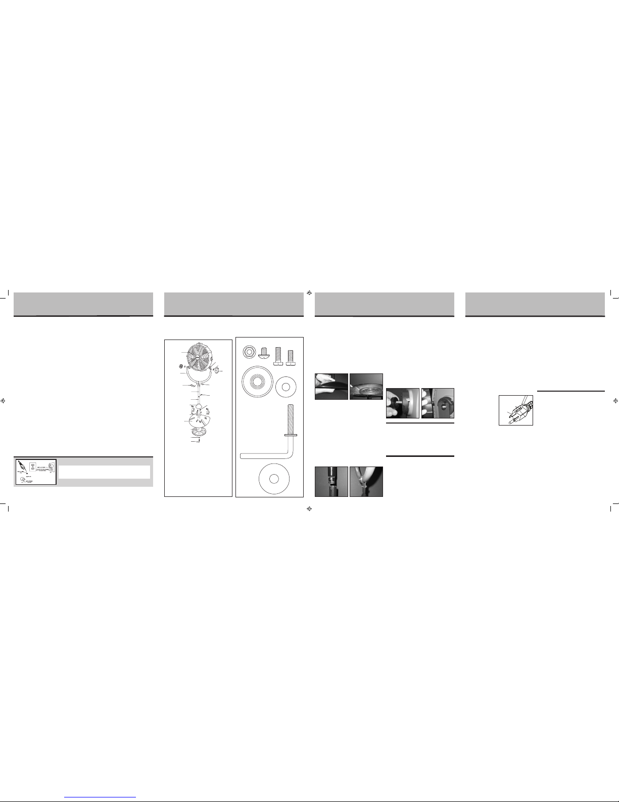
Figure 1
A. Fan Housing
B. Yoke with Bracket
C. Long M6 Screws (3, for
the Yoke Attachment)
D. Upper Pole
E. Lower Pole
F. Decorative Cap
G. Flange (attached to
Lower Pole)
H. Base
I. Base Weight
J. Large Washer (1, for
Base Weight)
K. Large “L” Base Screw
(for Base Weight)
L. Rubber Bushings (2)
M. Small Flat Washer (2,
for Tilt adjustment
Knobs)
N. Tilt Adjustment Knobs
(2)
O. Locking Nuts (7)
P. Pole Screw (Black)
Q. Short M6 Screws
(4, for Base)
A
L
M
N
O
P
Q
B
C
D
E
F
G
H
I
J
K
CLEANING/MAINTENANCE
INSTRUCTIONS
Follow these instructions to correctly and safely care for
your fan. Please remember:
REPLACEABLE FUSE
If your (5 Amp, 125 Volt) replaceable fuse blows, please
order a new fuse at 1-800-333-1930. Follow the below
instructions to replace the fuse on the plug.
User Servicing Instructions
1. Unplug your fan. Grasp plug and remove from the
receptacle or other outlet device. Do not unplug by
pulling on cord.
2. Open fuse cover, located on the top of the plug, by
using your thumb or a flathead screwdriver to slide
the cover down towards the prongs.
Note: Ensure that fuse cover is completely open
before attempting to remove fuse.
3. Remove fuse carefully
by using a small
screwdriver to pry the
fuse out of the
compartment by the
metal ends of the fuse
(see Figure 9).
4. Place plug on a solid,
flat surface. Insert new
5 Amp, 125 Volt fuse into fuse compartment and use
a small screwdriver to secure the metal ends of the
fuse into the compartment.
Caution: Risk of fire. Replace fuse only with 5 Amp,
125 Volt fuse.
5. Slide fuse cover closed completely. If fuse cover is
difficult to close, make sure fuse is secured in place
completely by pressing down on metal ends of the
fuse.
6. Risk of fire. Do not replace attachment plug. Contains
a safety device (fuse) that should not be removed.
Discard product if the attachment plug is damaged.
FAN CLEANING
• Alwaysunplugthefanbeforecleaningor
disassembling.
• Donotallowwatertodriponorenter intofan
housing.
• Besuretouseasoftclothmoistenedwith amild
soap solution.
• Donotuseanyofthefollowingasa cleaner:
gasoline, thinner, or benzene.
To clean the blade remove the front grill by loosening the
eight screws securing the grill to the motor housing. After
cleaning the blade secure the front grill back to the motor
housing by reinstalling the eight screws.
Clean the fan blade, grill, housing and base with a soft,
damp cloth. Please use caution around the motor housing
area. Do not allow the motor or other electrical
components to be exposed to water.
FAN STORAGE
When storing your fan in the off season, it is important to
keep it in a safe dry location. It is important to protect
the fan head from dust.
Rubber Bushing (2)
M6 Nut (7)
Flat Washer (2)
Pole Screw
(Black) (1)
M6 Long Screw
(for Yoke
Attachment) (3)
M6 Short Screw
(for Base
Attachment) (4)
Large "L" Base Screw (1)
Large Washer (1)
Figure 2
Figure 7
Figure 8
Figure 4Figure 3
Figure 5 Figure 6
Fuse cover
Figure 9
Metal ends
Fuse
PX405PED_11EM1.indd 2 7/14/11 5:12 PM
 Loading...