

Patton OnSite OS3300 Quick Start Manual

OnSite™ Model 3300
EFM Router
Quick Start Guide
Important—This is a Class A device and is not intended nor approved
for use in an industrial or residential environment.
Part Number: 07MOS3300-QS, Rev. B
Revised: May 18, 2018
Sales Office: +1 (301) 975-1000
Technical Support: +1 (301) 975-1007
E-mail: support@patton.com
WWW: www.patton.com

2 OnSite OS3300 Quick Start Guide
• Do not open the device when the power cord is connected. For sys-
tems without a power switch and without an external power
adapter, line voltages are present within the device when the power
cord is connected.
• For devices with an external power adapter, the power adapter shall
be a listed Limited Power Source. The mains outlet that is utilized
to power the device shall be within 10 feet (3 meters) of the device,
shall be easily accessible, and protected by a circuit breaker in
compliance with local regulatory requirements.
• For AC powered devices, ensure that the power cable used meets
all applicable standards for the country in which it is to be
installed.
• For AC powered devices which have 3 conductor power plugs (L1,
L2 & GND or Hot, Neutral & Safety/Protective Ground), the wall outlet (or socket) must have an earth ground.
• For DC powered devices, ensure that the interconnecting cables are
rated for proper voltage, current, anticipated temperature, flammability, and mechanical serviceability.
• WAN, LAN & PSTN ports (connections) may have hazardous volt-
ages present regardless of whether the device is powered ON or
OFF. PSTN relates to interfaces such as telephone lines, FXS, FXO,
DSL, xDSL, T1, E1, ISDN, Voice, etc. These are known as ?hazardous network voltages? and to avoid electric shock use caution when
workin3g near these ports. When disconnecting cables for these
ports, detach the far end connection first.
• Do not work on the device or connect or disconnect cables during
periods of lightning activity.
This device contains no user serviceable parts. This device can only
be repaired by qualified service personnel.
This device is NOT intended nor approved for connection to the PSTN.
It is intended only for connection to customer premise equipment.
WARNING
WARNING
WARNING
OnSite OS3300 Quick Start Guide 3
1.0 Hardware Installation
1.1 Contents of Package
• OS3300 EFM Router
• External power supply for OnSite Model 3300
• Ethernet cable with RJ45 plugs on each end (included)
1.2 What you will need
• Default unit IP address: 192.168.200.10
• Default username: admin
• Default password: (no password)
• PC Computer
1.3 Identify the connector and attach the cables
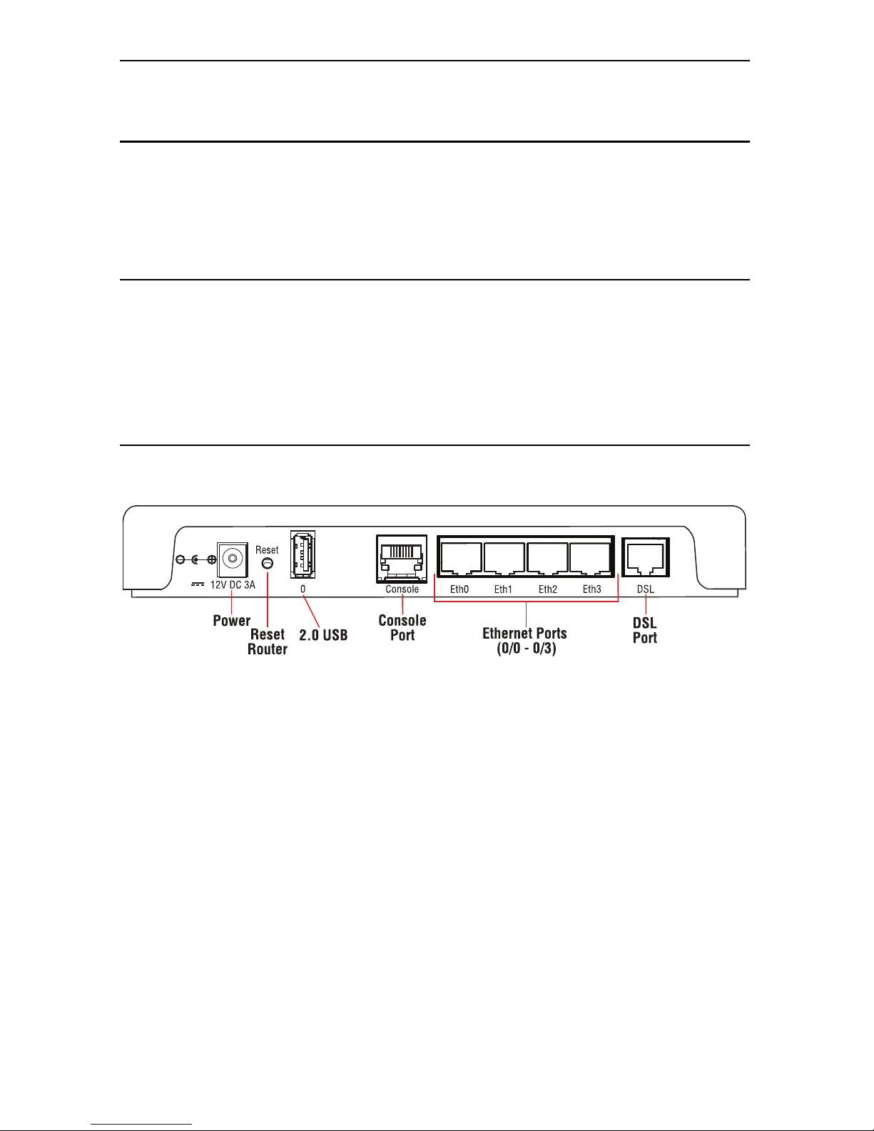
All connectors are on the rear panel of the OS3300 Router.
Figure 1. OS3300 EFM Router rear panel connectors
Connect the DSL Interface
To function properly, the OS3300 must be connected using a twisted-pair, unconditioned, dry, metal wire, between 19 (0.9mm) and 26 AWG (0.4mm). Leased circuits that
run through signal equalization equipment are not acceptable.
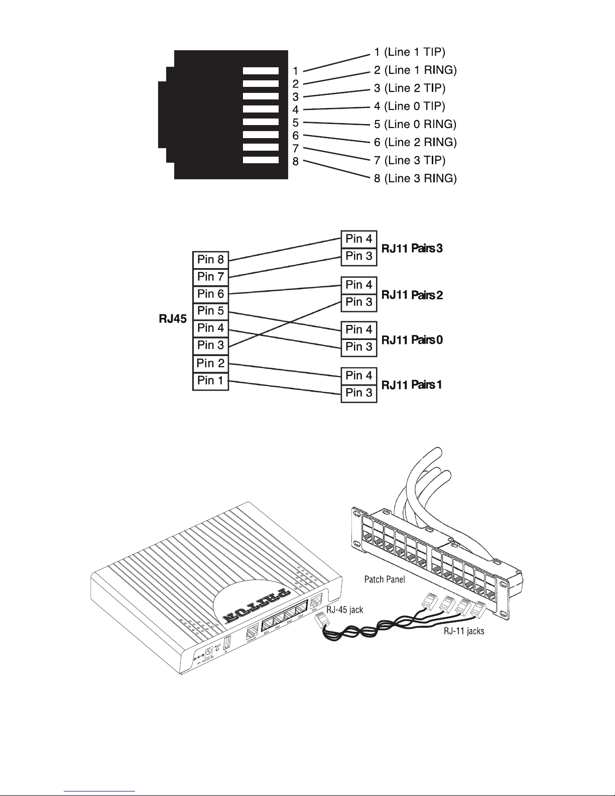
The EFM Router is equipped with a RJ-45 interface jack (DSL), which conforms to the
T568B standard. Any standard Category 5e cable can be used to directly connect two
routers. Depending on the router model, it will have a two-wire, four-wire or eight-wire
interface. Observe the signal/pin relationship on the OS3300’s DSL interface jack for
each pair in figure 2 on page 4. Figure 4 on page 4 shows the proper way to wire a
cable with a RJ-45 jack on one end and four RJ-11jacks on the other.
4 OnSite OS3300 Quick Start Guide
Figure 2. OS3300 (RJ-45) twisted pair DSL interface
Figure 3. OnSite Pinout for two devices
Figure 4. RJ-45 to RJ-11 cable
OnSite OS3300 Quick Start Guide 5
2.0 Connecting Interfaces
2.1 Connecting Console Interface
Install the supplied RJ-45-to-RJ-45 cable with the DB9-RJ45 adapter between the
OS3300 RS-232 port and an open serial port on your computer. If you need to assemble your own cable, refer to the pinout diagram in figure 5.
Figure 5. DB-9-to-RJ-45 cable diagram
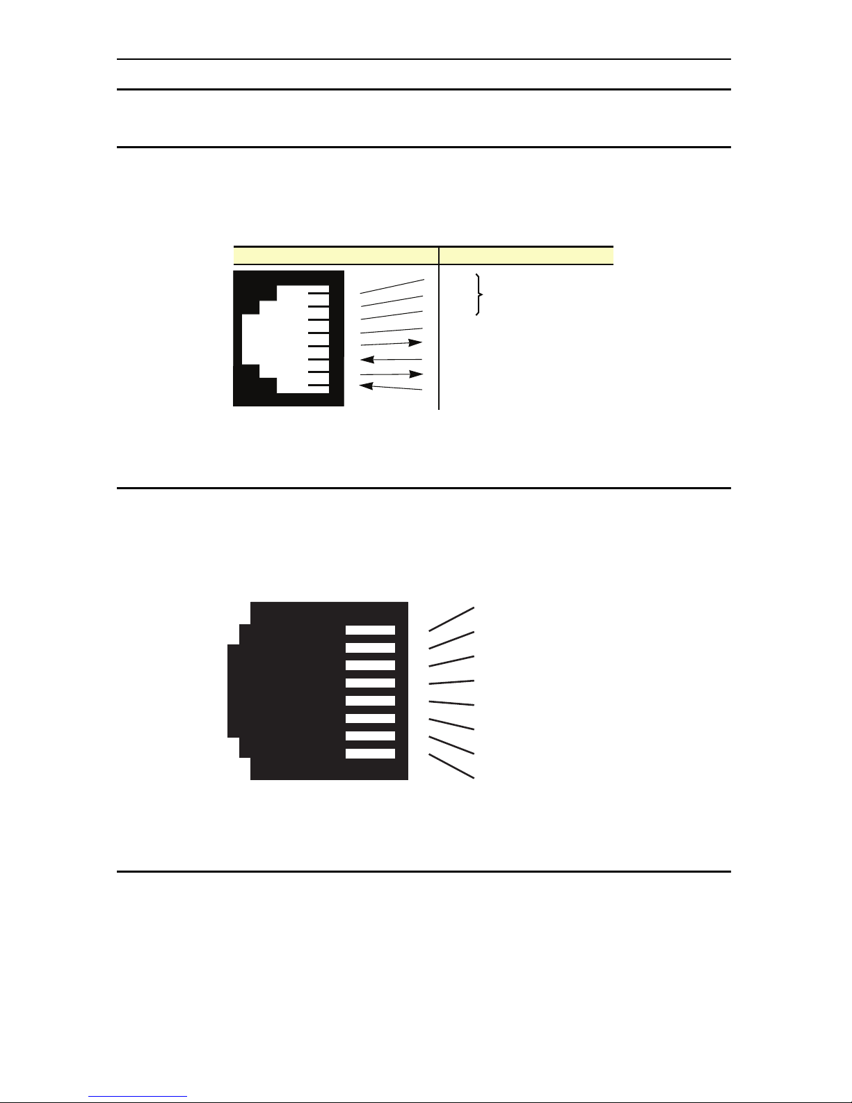
2.2 Connect the Ethernet Interface
The EFM Router has four unshielded RJ-45 auto-MDIX10/100Base-T interfaces. These
are designed to connect directly to a 10/100Base-TX network. Figure 6 shows the signal/pin relationships on this interface. You may connect this port to a hub or PC using a
straight through or crossover cable that is up to 328 ft long.
Figure 6. OS330010/100Base-T RJ-45 Connector Pinout
2.3 Connect the Power Source
The EFM Router does not have a power switch; it powers on once the device is plugged
in. The power connection is made via the barrel jack on the rear panel of the OS3300.
No configuration is necessary for the power supply.
6 DSR
1 CD
4 DTR
5 SG
2 RD (driven by access server)
3 TD (received by access server)
8 CTS (driven by access server)
7 RTS (received by access server)
1
2
3
4
5
6
7
8
Wired together
(No other electrical
connection)
RJ-45 Jack Signal NameDB-9
1 TX+ (data output)
2 TX- (data output)
3 RX+ (data input)
4 (no connection)
5 (no connection)
6 RX- (data input)
7 (no connection)
8 (no connection)
1
2
3
4
5
6
7
8
6 OnSite OS3300 Quick Start Guide
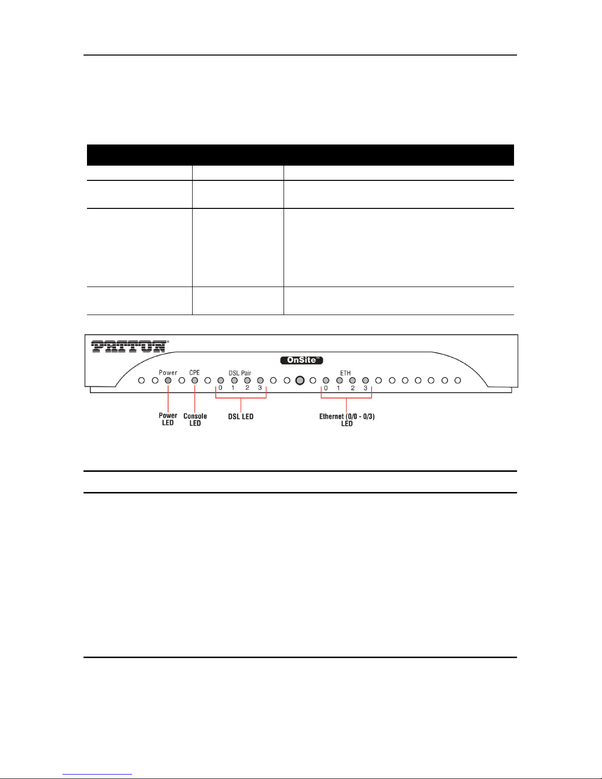
2.4 Router/Bridge Status LEDs
The LEDs indicate the status of power, the WAN (OnSite), and Ethernet connections.
Note When powered down, the LED indicators are clear; when powered on, the LED
indicators are yellow.
Figure 7. OS3300 front panel
3.0 CLI Operation and Configuration
You can connect a PC to configure the OnSite 3300 using the CLI. The 3300 EFM
Router comes equipped with an password protected (easy to use) Command Line
Interface. You can connect directly to the unit and make changes immediately by using
the Console Connection or a SSH connection to the default IP address:
192.168.200.10/24. SSH is enabled by default, Telnet is disabled by default for security
reasons. In this section you can see how easy it is to change IP address, username and
save your configuration. On page 9 you can see a sample configuration for easy connections to Central EFM DSLAM or EFM Peer Router.
3.1 Connect with SSH
1. Connect the Ethernet cable.
2. Connect the power supply.
Table 1. OS3300 front panel LEDs
LED Name LED Function Description
Power ON Indicates power is applied.
R
OFF
ON
WAN is configured as CO.
WAN is configured as CPE.
OnSite Pair
(one LED for each
port [1 on OS3301,
2 on OS3302, 4 on
OS3304])
OFF
ON
SLOW BLINK
FAST BLINK
Port is configured as DOWN.
Port is in data mode.
Port is in handshake mode (looking for a CPE
signal).
Port is in training mode (active communication with CPE).
Ethernet
(0/0 - 0/3)
ON
OFF
Port is linked.
Data is passing over the port.
 Loading...