

Page 1

IPLink Series
IPLink Software Release 3.20
Software Configuration Guide
Sales Office: +1 (301) 975-1000
Technical Support: +1 (301) 975-1007
E-mail: support@patton.com
URL: www.patton.com
Document Number: 13220U8-001 Rev. A
Part Number: 07M2800-SCG
Revised: May 3, 2006
Page 2

Patton Electronics Company, Inc.
7622 Rickenbacker Drive
Gaithersburg, MD 20879 USA
Tel: +1 (301) 975-1000
Fax: +1 (301) 869-9293
Support: +1 (301) 975-1007
Web: www.patton.com
E-mail: support@patton.com
Copyright © 2006, Patton Electronics Company. All rights reserved.
The information in this document is subject to change without notice. Patton Elec-
tronics assumes no liability for errors that may appear in this document.
Trademark Statement
The term IPLink is a trademark of Patton Electronics Company. All other trademarks presented in this document are the property of their respective owners.
Notices
The information contained in this document is not designed or intended for use as critical components in
human life-support systems, equipment used in hazardous environments, or nuclear control systems. Patton
Electronics Company disclaims any express or implied warranty of fitness for such uses.
The information in this document is subject to change without notice. Patton Electronics assumes no liability for errors that may appear in this document.
Any software described in this document is furnished under license and may be used or copied only in accordance with the terms of such license.
Released Build Numbers
This version of the Software Configuration Guide is based on IPLink 3.20 Build Series 2006-02-02 . The
following are the applicable released build numbers:
IPLink 2805 R3.20
Build 2006-03-03
Supported Platforms
IPLink Model 2805
(Rev. B)
IPLink 2802/2821/2835 R3.20
Build 2006-0-03
IPLink 2802/2821/2835
(Rev. D)
Page 3

Summary Table of Contents
1 System overview .............................................................................................................................................24
2 Configuration concepts ..................................................................................................................................29
3 Command line interface (CLI) .......................................................................................................................33
4 Accessing the CLI...........................................................................................................................................38
5 Establishing basic IP connectivity..................................................................................................................50
6 System image handling...................................................................................................................................57
7 Configuration file handling............................................................................................................................71
8 Basic system management ..............................................................................................................................87
9 RADIUS Client Configuration.......................................................................................................................99
10 IP context overview ......................................................................................................................................110
11 IP interface configuration ............................................................................................................................117
12 NAT/NAPT configuration............................................................................................................................128
13 Ethernet port configuration .........................................................................................................................137
14 Link scheduler configuration .......................................................................................................................148
15 Serial port configuration ..............................................................................................................................167
16 T1/E1 port configuration.............................................................................................................................185
17 Basic IP routing configuration.....................................................................................................................195
18 RIP configuration ........................................................................................................................................201
19 Access control list configuration...................................................................................................................211
20 SNMP configuration ....................................................................................................................................225
21 SNTP client configuration ...........................................................................................................................240
22 DHCP configuration....................................................................................................................................251
23 DNS configuration.......................................................................................................................................261
24 DynDNS configuration................................................................................................................................265
25 PPP configuration........................................................................................................................................270
26 VPN configuration .......................................................................................................................................287
A Terms and definitions .................................................................................................................................304
B Mode summary ...........................................................................................................................................309
C Command summary ....................................................................................................................................313
D Internetworking terms & acronyms ............................................................................................................325
E Used IP ports in the IPLink software ..........................................................................................................330
3
Page 4

Table of Contents
Summary Table of Contents ............................................................................................................................3
Table of Contents ............................................................................................................................................4
List of Figures ................................................................................................................................................16
List of Tables .................................................................................................................................................17
About this guide ............................................................................................................................................18
Audience............................................................................................................................................................... 18
How to read this guide ......................................................................................................................................... 18
Structure............................................................................................................................................................... 18
Precautions........................................................................................................................................................... 20
Typographical conventions used in this document................................................................................................ 21
General conventions .......................................................................................................................................21
Mouse conventions .........................................................................................................................................22
Service and support ...............................................................................................................................................22
Patton support headquarters in the USA .........................................................................................................22
Alternate Patton support for Europe, Middle East, and Africa (EMEA) ..........................................................22
Warranty Service and Returned Merchandise Authorizations (RMAs)...................................................................23
Warranty coverage ..........................................................................................................................................23
Returns for credit ......................................................................................................................................23
Return for credit policy .............................................................................................................................23
RMA numbers ................................................................................................................................................23
Shipping instructions ................................................................................................................................23
1 System overview .............................................................................................................................................24
Introduction..........................................................................................................................................................25
IPLink hardware platforms ....................................................................................................................................26
IPLink software embedded software ......................................................................................................................26
IPLink Software management center tools.............................................................................................................27
2 Configuration concepts ..................................................................................................................................29
Introduction..........................................................................................................................................................30
Contexts and Gateways .........................................................................................................................................31
Context ...........................................................................................................................................................31
Interfaces, Ports, and Bindings ..............................................................................................................................31
Interfaces ........................................................................................................................................................31
Ports and circuits ............................................................................................................................................31
Bindings .........................................................................................................................................................32
Profiles and Use commands...................................................................................................................................32
Profiles ............................................................................................................................................................32
Use Commands ..............................................................................................................................................32
3 Command line interface (CLI) .......................................................................................................................33
Introduction..........................................................................................................................................................34
4
Page 5

5
IPLink Software Configuration Guide
Table of Contents
Command modes..................................................................................................................................................34
CLI prompt ....................................................................................................................................................34
Navigating the CLI .........................................................................................................................................35
Initial mode ..............................................................................................................................................35
System changes .........................................................................................................................................35
Configuration ...........................................................................................................................................35
Changing Modes .......................................................................................................................................35
Command editing .................................................................................................................................................35
Command help ...............................................................................................................................................35
The No form ..................................................................................................................................................35
Command defaults—returning parameters to default values ...........................................................................36
Command completion ....................................................................................................................................36
Command history ...........................................................................................................................................36
Command Editing Shortcuts ..........................................................................................................................36
4 Accessing the CLI...........................................................................................................................................38
Introduction..........................................................................................................................................................39
Accessing the IPLink software CLI task list............................................................................................................39
Accessing via the console port .........................................................................................................................40
Console port procedure .............................................................................................................................40
Accessing via a Telnet session ..........................................................................................................................41
Telnet Procedure .......................................................................................................................................41
Using an alternate TCP listening port for the Telnet server .............................................................................42
Disabling the Telnet server .............................................................................................................................42
Logging onto the IPLink software ...................................................................................................................42
Selecting a secure password .............................................................................................................................43
Password encryption .......................................................................................................................................43
Configure operators and administrators ..........................................................................................................44
Password encryption .................................................................................................................................44
Factory preset administrator account .........................................................................................................44
Creating an operator account ....................................................................................................................44
Creating an administrator account ............................................................................................................45
Displaying the CLI version .............................................................................................................................45
Displaying account information ......................................................................................................................46
Switching to another account ..........................................................................................................................46
Checking identity and connected users ...........................................................................................................47
Command index numbers ..............................................................................................................................47
Ending a Telnet or console port session ..........................................................................................................49
Hidden commands in .cfg configuration files ..................................................................................................49
5 Establishing basic IP connectivity..................................................................................................................50
Introduction..........................................................................................................................................................51
IP context selection and basic interface configuration tasks.................................................................................... 51
Entering the IP context, creating IP interfaces and assigning an IP address .....................................................51
Defining IP Ethernet encapsulation and binding an IP interface to a physical port .........................................52
Page 6

6
IPLink Software Configuration Guide
Table of Contents
Activating a physical port ................................................................................................................................52
Displaying IP interface information ................................................................................................................53
Deleting IP interfaces ......................................................................................................................................54
Examples ...............................................................................................................................................................55
Setting up an IP interface on an Ethernet port ................................................................................................55
6 System image handling...................................................................................................................................57
Introduction..........................................................................................................................................................58
Memory regions in IPLink software.......................................................................................................................58
System image handling task list .............................................................................................................................60
Displaying system image information .............................................................................................................60
Copying system images from a network server to Flash memory .....................................................................61
Copying driver software from a network server to Flash memory ....................................................................62
Auto provisioning of firmware and configuration ..................................................................................................63
Boot procedure......................................................................................................................................................65
Bootloader.............................................................................................................................................................67
Start Bootloader ..............................................................................................................................................67
Start-up with factory configuration .................................................................................................................68
Load a new application image (IPLink software) via TFTP .............................................................................68
Load a new application image (IPLink software) via the serial link ..................................................................70
Factory configuration ............................................................................................................................................70
7 Configuration file handling............................................................................................................................71
Introduction..........................................................................................................................................................72
Understanding configuration files ...................................................................................................................72
Factory configuration ............................................................................................................................................74
Configuration file handling task list.......................................................................................................................74
Copying configurations within the local memory ............................................................................................75
Replacing the startup configuration with a configuration from Flash memory ................................................76
Copying configurations to and from a remote storage location .......................................................................78
Replacing the startup configuration with a configuration downloaded from TFTP server ...............................79
Displaying configuration file information .......................................................................................................80
Modifying the running configuration at the CLI ............................................................................................80
Modifying the running configuration offline ...................................................................................................81
Deleting a specified configuration ...................................................................................................................83
Encrypted file download .................................................................................................................................83
Encrypted Configuration Download .........................................................................................................84
Use Cases ..................................................................................................................................................84
8 Basic system management ..............................................................................................................................87
Introduction..........................................................................................................................................................88
Basic system management configuration task list ................................................................................................... 88
Managing feature license keys .........................................................................................................................89
Setting system information .............................................................................................................................90
Setting the system banner ...............................................................................................................................91
Setting time and date ......................................................................................................................................92
Page 7

7
IPLink Software Configuration Guide
Table of Contents
Display clock information ...............................................................................................................................92
Display time since last restart ..........................................................................................................................93
Configuring and starting the Web server .........................................................................................................93
Determining and defining the active CLI version ............................................................................................93
Restarting the system ......................................................................................................................................94
Displaying the system logs ..............................................................................................................................95
Controlling command execution .....................................................................................................................95
Timed execution of CLI command .................................................................................................................97
Displaying the checksum of a configuration ....................................................................................................97
Configuration of terminal sessions ..................................................................................................................97
9 RADIUS Client Configuration.......................................................................................................................99
Introduction........................................................................................................................................................100
The AAA component ..........................................................................................................................................100
General AAA Configuration .........................................................................................................................101
RADIUS configuration .......................................................................................................................................103
Configuring RADIUS clients ........................................................................................................................104
Configuring RADIUS accounting .................................................................................................................105
Configuring the RADIUS server ...................................................................................................................107
Attributes in the RADIUS request message .............................................................................................107
Attributes in the RADIUS accept message ...............................................................................................108
Configuring the local database accounts ..............................................................................................................108
10 IP context overview ......................................................................................................................................110
Introduction........................................................................................................................................................111
IP context overview configuration task list...........................................................................................................111
Planning your IP configuration ...........................................................................................................................112
IP interface related information ....................................................................................................................112
Serial interface related information ................................................................................................................113
QoS related information ...............................................................................................................................113
Configuring Ethernet and serial ports..................................................................................................................113
Creating and configuring IP interfaces.................................................................................................................113
Configuring NAPT .............................................................................................................................................114
Configuring static IP routing............................................................................................................................... 114
Configuring RIP..................................................................................................................................................114
Configuring access control lists............................................................................................................................115
Configuring quality of service (QoS) ...................................................................................................................115
11 IP interface configuration ............................................................................................................................117
Introduction........................................................................................................................................................118
Software IP interface configuration task list .........................................................................................................118
Creating an IP interface ................................................................................................................................118
Deleting an IP interface ................................................................................................................................119
Setting the IP address and netmask ...............................................................................................................120
Configuring a NAPT DMZ interface ............................................................................................................120
ICMP message processing .............................................................................................................................121
Page 8

8
IPLink Software Configuration Guide
Table of Contents
ICMP redirect messages ................................................................................................................................121
Router advertisement broadcast message .......................................................................................................121
Defining the MTU and MSS of the interface ................................................................................................122
Configuring an interface as a point-to-point link ..........................................................................................123
Displaying IP interface information ..............................................................................................................123
Displaying dynamic ARP entries ...................................................................................................................124
Flushing dynamic ARP entries ......................................................................................................................124
Testing connections with the ping command ................................................................................................124
Traceroute ....................................................................................................................................................125
Debug ARP ..................................................................................................................................................125
Configuring the IGMP Proxy.............................................................................................................................. 126
Examples .............................................................................................................................................................127
Deleting an IP interface ................................................................................................................................127
12 NAT/NAPT configuration............................................................................................................................128
Introduction........................................................................................................................................................129
Dynamic NAPT ...........................................................................................................................................129
Static NAPT .................................................................................................................................................130
Dynamic NAT ..............................................................................................................................................131
Static NAT ...................................................................................................................................................131
NAPT traversal .............................................................................................................................................131
NAT/NAPT configuration task list .....................................................................................................................132
Creating a NAPT profile ...............................................................................................................................132
Configuring a NAPT DMZ host ............................................................................................................133
Defining NAPT port ranges ....................................................................................................................134
Preserving TCP/UDP port numbers in NAPT ........................................................................................134
Defining the UDP NAPT type ...............................................................................................................134
Activate NAT/NAPT ....................................................................................................................................135
Displaying NAT/NAPT configuration information ......................................................................................135
Configuring NAT static protocol entries .......................................................................................................136
13 Ethernet port configuration .........................................................................................................................137
Introduction........................................................................................................................................................138
Ethernet port configuration task list ....................................................................................................................138
Entering the Ethernet port configuration mode ............................................................................................139
Configuring medium for an Ethernet port ....................................................................................................139
Configuring Ethernet encapsulation type for an Ethernet port ......................................................................140
Binding an Ethernet port to an IP interface ..................................................................................................140
Multiple IP addresses on Ethernet ports ........................................................................................................141
Configuring a VLAN ....................................................................................................................................142
Configuring layer 2 CoS to service-class mapping for an Ethernet port .........................................................143
Adding a receive mapping table entry ......................................................................................................144
Adding a transmit mapping table entry ...................................................................................................145
Closing an Ethernet port ...............................................................................................................................145
Using the built-in Ethernet sniffer.......................................................................................................................146
Page 9

9
IPLink Software Configuration Guide
Table of Contents
14 Link scheduler configuration .......................................................................................................................148
Introduction........................................................................................................................................................149
Applying scheduling at the bottleneck ...........................................................................................................149
Using traffic classes .......................................................................................................................................149
Introduction to Scheduling ...........................................................................................................................150
Priority ....................................................................................................................................................150
Weighted fair queuing (WFQ) ................................................................................................................150
Shaping ...................................................................................................................................................150
Burst tolerant shaping or wfq ..................................................................................................................151
Hierarchy ................................................................................................................................................151
Quick references..................................................................................................................................................152
Setting the modem rate .................................................................................................................................152
Command cross reference .............................................................................................................................153
Link scheduler configuration task list...................................................................................................................153
Defining the access control list profile ...........................................................................................................154
Packet classification .................................................................................................................................154
Creating an access control list ..................................................................................................................155
Creating a service policy profile .....................................................................................................................156
Specifying the handling of traffic-classes .......................................................................................................158
Defining fair queuing weight ...................................................................................................................158
Defining the bit-rate ...............................................................................................................................159
Defining absolute priority .......................................................................................................................159
Defining the maximum queue length ......................................................................................................159
Specifying the type-of-service (TOS) field ...............................................................................................159
Specifying the precedence field ................................................................................................................160
Specifying differentiated services codepoint (DSCP) marking .................................................................160
Specifying layer 2 marking ......................................................................................................................161
Defining random early detection .............................................................................................................162
Discarding Excess Load ...........................................................................................................................162
Quality of Service for routed RTP streams ....................................................................................................162
Devoting the service policy profile to an interface .........................................................................................164
Displaying link arbitration status ..................................................................................................................165
Displaying link scheduling profile information .............................................................................................165
Enable statistics gathering .............................................................................................................................165
15 Serial port configuration ..............................................................................................................................167
Introduction........................................................................................................................................................168
Serial port configuration task list .........................................................................................................................168
Disabling an interface ...................................................................................................................................169
Enabling an interface ....................................................................................................................................169
Configuring the serial encapsulation type ......................................................................................................170
Configuring the active clock edge .................................................................................................................171
Configuring the baudrate ..............................................................................................................................172
Enter Frame Relay mode ...............................................................................................................................173
Page 10

10
IPLink Software Configuration Guide
Table of Contents
Configuring the LMI type ............................................................................................................................173
Configuring the keep-alive interval ...............................................................................................................174
Enabling fragmentation ................................................................................................................................174
Entering Frame Relay PVC configuration mode ...........................................................................................176
Configuring the PVC encapsulation type ......................................................................................................177
Binding the Frame Relay PVC to IP interface ...............................................................................................177
Enabling a Frame Relay PVC ........................................................................................................................179
Disabling a Frame Relay PVC .......................................................................................................................179
Debugging Frame Relay ................................................................................................................................180
Displaying serial port information .................................................................................................................181
Displaying Frame Relay information .............................................................................................................181
Integrated service access ................................................................................................................................182
16 T1/E1 port configuration.............................................................................................................................185
Introduction........................................................................................................................................................186
T1/E1 port configuration task list........................................................................................................................186
Enable/Disable T1/E1 port ...........................................................................................................................186
Configuring T1/E1 port-type .......................................................................................................................187
Configuring T1/E1 clock-mode ....................................................................................................................187
Configuring T1/E1 line-code ........................................................................................................................187
Configuring T1/E1 framing ..........................................................................................................................187
Configuring T1/E1 line-build-out (T1 only) ................................................................................................188
Configuring T1/E1 used-connector (E1 only) ...............................................................................................188
Configuring T1/E1 application mode ...........................................................................................................188
Configuring T1/E1 LOS threshold ...............................................................................................................189
Configuring T1 Loopback detection .............................................................................................................189
Configuring T1/E1 encapsulation .................................................................................................................190
Create a Channel-Group ...............................................................................................................................190
Configuring Channel-Group Timeslots ........................................................................................................191
Configuring Channel-Group Encapsulation .................................................................................................191
Entering HDLC Configuration Mode ..........................................................................................................191
Configuring HDLC CRC-Type ...................................................................................................................192
Configuring HDLC Encapsulation ...............................................................................................................192
T1/E1 Configuration Examples ....................................................................................................................192
Example 1: Frame Relay without a channel-group ..................................................................................193
Example 2: Framerelay with a channel-group ..........................................................................................194
Example 3: PPP without a channel-group ...............................................................................................194
Example 4: PPP with a channel-group ....................................................................................................194
17 Basic IP routing configuration.....................................................................................................................195
Introduction........................................................................................................................................................196
Routing tables ...............................................................................................................................................196
Static routing ................................................................................................................................................196
Basic IP routing configuration task list ................................................................................................................196
Configuring static IP routes ..........................................................................................................................196
Page 11

11
IPLink Software Configuration Guide
Table of Contents
Deleting static IP routes ................................................................................................................................197
Displaying IP route information ...................................................................................................................198
Examples .............................................................................................................................................................199
Basic static IP routing example ......................................................................................................................199
Changing the default UDP port range for RTP and RTCP.................................................................................200
18 RIP configuration ........................................................................................................................................201
Introduction........................................................................................................................................................202
Routing protocol .................................................................................................................................................202
RIP configuration task list ...................................................................................................................................203
Enabling send RIP ........................................................................................................................................203
Enabling an interface to receive RIP ..............................................................................................................204
Specifying the send RIP version ....................................................................................................................204
Specifying the receive RIP version .................................................................................................................205
Enabling RIP learning ...................................................................................................................................205
Enabling an interface to receive RIP ..............................................................................................................206
Enabling RIP announcing .............................................................................................................................206
Enabling RIP auto summarization ................................................................................................................207
Specifying the default route metric ................................................................................................................207
Enabling RIP split-horizon processing ..........................................................................................................208
Enabling the poison reverse algorithm ...........................................................................................................208
Enabling holding down aged routes ..............................................................................................................209
Displaying RIP configuration of an IP interface ............................................................................................209
Displaying global RIP information ...............................................................................................................210
19 Access control list configuration...................................................................................................................211
Introduction........................................................................................................................................................212
About access control lists ..................................................................................................................................... 212
What access lists do .......................................................................................................................................212
Why you should configure access lists ...........................................................................................................212
When to configure access lists .......................................................................................................................213
Features of access control lists .......................................................................................................................213
Access control list configuration task list..............................................................................................................214
Mapping out the goals of the access control list .............................................................................................214
Creating an access control list profile and enter configuration mode .............................................................215
Adding a filter rule to the current access control list profile ...........................................................................215
Adding an ICMP filter rule to the current access control list profile ..............................................................217
Adding a TCP, UDP or SCTP filter rule to the current access control list profile .........................................219
Binding and unbinding an access control list profile to an IP interface ..........................................................221
Displaying an access control list profile .........................................................................................................222
Debugging an access control list profile .........................................................................................................222
Examples .............................................................................................................................................................224
Denying a specific subnet ..............................................................................................................................224
20 SNMP configuration ....................................................................................................................................225
Introduction........................................................................................................................................................226
Page 12

12
IPLink Software Configuration Guide
Table of Contents
Simple Network Management Protocol (SNMP) ................................................................................................226
SNMP basic components ..............................................................................................................................226
SNMP basic commands ................................................................................................................................226
SNMP management information base (MIB) ...............................................................................................227
Network management framework .................................................................................................................227
Identification of the IPLink devices via SNMP....................................................................................................228
SNMP tools.........................................................................................................................................................228
SNMP configuration task list ..............................................................................................................................228
Setting basic system information .........................................................................................................................229
Setting access community information ................................................................................................................231
Setting allowed host information.........................................................................................................................232
Specifying the default SNMP trap target .............................................................................................................232
Displaying SNMP related information ................................................................................................................ 233
Using the AdventNet SNMP utilities ..................................................................................................................234
Using the MibBrowser ..................................................................................................................................234
Using the TrapViewer ...................................................................................................................................235
Standard SNMP version 1 traps ..........................................................................................................................237
SNMP interface traps .......................................................................................................................................... 239
21 SNTP client configuration ...........................................................................................................................240
Introduction........................................................................................................................................................241
SNTP client configuration task list......................................................................................................................241
Selecting SNTP time servers .........................................................................................................................242
Defining SNTP client operating mode ..........................................................................................................242
Defining SNTP local UDP port ...................................................................................................................243
Enabling and disabling the SNTP client .......................................................................................................244
Defining SNTP client poll interval ...............................................................................................................244
Defining SNTP client constant offset to GMT .............................................................................................244
Defining the SNTP client anycast address .....................................................................................................245
Enabling and disabling local clock offset compensation .................................................................................246
Showing SNTP client related information ....................................................................................................247
Debugging SNTP client operation ................................................................................................................247
Recommended public SNTP time servers............................................................................................................ 248
NIST Internet time service ............................................................................................................................248
Other public NTP primary (stratum 1) time servers .....................................................................................249
Additional information on NTP and a list of other NTP servers ...................................................................250
Recommended RFC .....................................................................................................................................250
22 DHCP configuration....................................................................................................................................251
Introduction........................................................................................................................................................252
DHCP-client configuration tasks ........................................................................................................................253
Enable DHCP-client on an IP interface ........................................................................................................253
Release or renew a DHCP lease manually (advanced) ...................................................................................255
Get debug output from DHCP-client ...........................................................................................................255
DHCP-server configuration tasks ........................................................................................................................256
Page 13

13
IPLink Software Configuration Guide
Table of Contents
Configure DHCP-server profiles ...................................................................................................................256
Use DHCP-server profiles and enable the DHCP-server ...............................................................................258
Check DHCP-server configuration and status ..............................................................................................259
Get debug output from the DHCP-server .....................................................................................................259
23 DNS configuration.......................................................................................................................................261
Introduction........................................................................................................................................................262
DNS configuration task list .................................................................................................................................262
Enabling the DNS resolver ...........................................................................................................................262
Enabling the DNS relay ................................................................................................................................263
24 DynDNS configuration................................................................................................................................265
Introduction........................................................................................................................................................266
DynDNS configuration task list ..........................................................................................................................266
Creating a DynDNS account ........................................................................................................................266
Configuring the DNS resolver ......................................................................................................................266
Configuring basic DynDNS settings .............................................................................................................267
Configuring advanced DynDNS settings (optional) ......................................................................................267
Defining a mail exchanger for your hostname .........................................................................................267
Troubleshooting ...........................................................................................................................................268
25 PPP configuration........................................................................................................................................270
Introduction........................................................................................................................................................271
PPP configuration task list................................................................................................................................... 272
Creating an IP interface for PPP ...................................................................................................................272
Disable interface IP address auto-configuration from PPP ............................................................................274
Creating a PPP subscriber .............................................................................................................................274
Trigger forced reconnect of PPP sessions using a timer .................................................................................275
Disable interface IP address auto-configuration from PPP ............................................................................276
Configuring a PPPoE session ........................................................................................................................276
Configuring a serial port for PPP ..................................................................................................................278
Creating a PPP profile ...................................................................................................................................279
Displaying PPP configuration information ...................................................................................................280
Debugging PPP ............................................................................................................................................281
Sample configurations .........................................................................................................................................285
PPP over Ethernet (PPPoE) ..........................................................................................................................285
Without authentication, encapsulation multi, with NAPT ......................................................................285
With authentication, encapsulation PPPoE .............................................................................................285
PPP over serial link .......................................................................................................................................286
Without authentication, numbered interface ...........................................................................................286
With authentication, unnumbered interface ............................................................................................286
26 VPN configuration .......................................................................................................................................287
Introduction........................................................................................................................................................288
Authentication ..............................................................................................................................................288
Encryption ....................................................................................................................................................288
Page 14

14
IPLink Software Configuration Guide
Table of Contents
Transport and tunnel modes .........................................................................................................................289
Key management ..........................................................................................................................................289
VPN configuration task list .................................................................................................................................289
Creating an IPsec transformation profile .......................................................................................................289
Creating an IPsec policy profile .....................................................................................................................290
Creating/modifying an outgoing ACL profile for IPsec .................................................................................292
Configuration of an IP interface and the IP router for IPsec .........................................................................293
Displaying IPsec configuration information ..................................................................................................293
Debugging IPsec ...........................................................................................................................................294
Key Management (IKE) ......................................................................................................................................295
Main differences between manual & IKE IPSEC configurations .............................................................295
Creating an IPSEC transform profile ......................................................................................................296
Creating an ISAKMP transform profile ...................................................................................................296
Creating an ISAKMP IPSEC policy profile .............................................................................................296
Creating/modifying an outgoing ACL profile for IPSEC .........................................................................298
Configuration of an IP interface and the IP router for IPSEC .................................................................298
Policy matching ......................................................................................................................................298
Sample configuration snippet ..................................................................................................................298
Troubleshooting ...........................................................................................................................................299
Using an alternate source IP address for specific destinations ...................................................................299
Sample configurations .........................................................................................................................................300
IPsec tunnel, DES encryption .......................................................................................................................300
IPLink configuration ...............................................................................................................................300
Cisco router configuration ......................................................................................................................301
IPsec tunnel, AES encryption at 256 bit key length, AH authentication with HMAC-SHA1-96 ..................301
IPLink configuration ...............................................................................................................................301
Cisco router configuration ......................................................................................................................302
IPsec tunnel, 3DES encryption at 192 bit key length, ESP authentication with HMAC-MD5-96 ................302
IPLink configuration ...............................................................................................................................302
Cisco router configuration ......................................................................................................................302
A Terms and definitions .................................................................................................................................304
Introduction........................................................................................................................................................305
IPLink software architecture terms and definitions ..............................................................................................305
B Mode summary ...........................................................................................................................................309
Introduction........................................................................................................................................................310
C Command summary ....................................................................................................................................313
Introduction........................................................................................................................................................314
Summary.............................................................................................................................................................315
operator_exec ................................................................................................................................................315
administrator_exec ........................................................................................................................................315
configure .......................................................................................................................................................317
radius-client ..................................................................................................................................................318
profile_acl .....................................................................................................................................................318
Page 15

15
IPLink Software Configuration Guide
Table of Contents
profile_service-policy ....................................................................................................................................319
profile_napt ..................................................................................................................................................319
profile_ppp ...................................................................................................................................................319
profile-ipsec-transform ..................................................................................................................................320
ipsec-manual-policy ......................................................................................................................................320
profile_dhcp-server .......................................................................................................................................320
profile_authentication ...................................................................................................................................321
profile_provisioning ......................................................................................................................................321
context_ip .....................................................................................................................................................321
interface ........................................................................................................................................................321
dyndns ..........................................................................................................................................................322
subscriber_ppp ..............................................................................................................................................322
port_ethernet ................................................................................................................................................322
pppoe ............................................................................................................................................................322
vlan ...............................................................................................................................................................323
port_serial .....................................................................................................................................................323
framerelay .....................................................................................................................................................323
Other ..................................................................................................................................................................324
Show help .....................................................................................................................................................324
Show command history ................................................................................................................................324
Show RedBoot version ..................................................................................................................................324
Restart system ...............................................................................................................................................324
Check network connection to remote system ................................................................................................324
D Internetworking terms & acronyms ............................................................................................................325
Abbreviations ......................................................................................................................................................326
E Used IP ports in the IPLink software ..........................................................................................................330
Used IP ports in the IPLink software...................................................................................................................331
Page 16

List of Figures
1 System overview with a Management Center . . . . . . . . . . . . . . . . . . . . . . . . . . . . . . . . . . . . . . . . . . . . . . . . . . 25
2 IPLink system model . . . . . . . . . . . . . . . . . . . . . . . . . . . . . . . . . . . . . . . . . . . . . . . . . . . . . . . . . . . . . . . . . . . . 26
3 IPLink Management System . . . . . . . . . . . . . . . . . . . . . . . . . . . . . . . . . . . . . . . . . . . . . . . . . . . . . . . . . . . . . . . 27
4 Configuration concept overview . . . . . . . . . . . . . . . . . . . . . . . . . . . . . . . . . . . . . . . . . . . . . . . . . . . . . . . . . . . . 30
5 Setup for initial configuration via the console port . . . . . . . . . . . . . . . . . . . . . . . . . . . . . . . . . . . . . . . . . . . . . . 40
6 Setup for initial configuration via an Ethernet port . . . . . . . . . . . . . . . . . . . . . . . . . . . . . . . . . . . . . . . . . . . . . . 41
7 Login display . . . . . . . . . . . . . . . . . . . . . . . . . . . . . . . . . . . . . . . . . . . . . . . . . . . . . . . . . . . . . . . . . . . . . . . . . . 42
8 Relation between IP Interface lan and Ethernet port 0 on slot 0 . . . . . . . . . . . . . . . . . . . . . . . . . . . . . . . . . . . . 55
9 IPLink memory regions logically defined in IPLink software . . . . . . . . . . . . . . . . . . . . . . . . . . . . . . . . . . . . . . 60
10 Boot procedure . . . . . . . . . . . . . . . . . . . . . . . . . . . . . . . . . . . . . . . . . . . . . . . . . . . . . . . . . . . . . . . . . . . . . . . . . 66
11 Sample configuration file . . . . . . . . . . . . . . . . . . . . . . . . . . . . . . . . . . . . . . . . . . . . . . . . . . . . . . . . . . . . . . . . . 73
12 Local memory regions in IPLink software . . . . . . . . . . . . . . . . . . . . . . . . . . . . . . . . . . . . . . . . . . . . . . . . . . . . . 75
13 Remote memory regions for IPLink software . . . . . . . . . . . . . . . . . . . . . . . . . . . . . . . . . . . . . . . . . . . . . . . . . . 78
14 System banner with message to operators . . . . . . . . . . . . . . . . . . . . . . . . . . . . . . . . . . . . . . . . . . . . . . . . . . . . . 91
15 Authentication procedure with a RADIUS server . . . . . . . . . . . . . . . . . . . . . . . . . . . . . . . . . . . . . . . . . . . . . . 101
16 How to use AAA methods and AAA profiles . . . . . . . . . . . . . . . . . . . . . . . . . . . . . . . . . . . . . . . . . . . . . . . . . . 101
17 IP context and related elements . . . . . . . . . . . . . . . . . . . . . . . . . . . . . . . . . . . . . . . . . . . . . . . . . . . . . . . . . . . 111
18 Dynamic NAPT . . . . . . . . . . . . . . . . . . . . . . . . . . . . . . . . . . . . . . . . . . . . . . . . . . . . . . . . . . . . . . . . . . . . . . . 130
19 Static NAPT . . . . . . . . . . . . . . . . . . . . . . . . . . . . . . . . . . . . . . . . . . . . . . . . . . . . . . . . . . . . . . . . . . . . . . . . . . 130
20 Dynamic NAT . . . . . . . . . . . . . . . . . . . . . . . . . . . . . . . . . . . . . . . . . . . . . . . . . . . . . . . . . . . . . . . . . . . . . . . . 131
21 Static NAT . . . . . . . . . . . . . . . . . . . . . . . . . . . . . . . . . . . . . . . . . . . . . . . . . . . . . . . . . . . . . . . . . . . . . . . . . . . 131
22 Binding of an Ethernet port to an IP interface . . . . . . . . . . . . . . . . . . . . . . . . . . . . . . . . . . . . . . . . . . . . . . . . 141
23 Packet routing in IPLink software . . . . . . . . . . . . . . . . . . . . . . . . . . . . . . . . . . . . . . . . . . . . . . . . . . . . . . . . . . 150
24 Example of Hierarchical Scheduling . . . . . . . . . . . . . . . . . . . . . . . . . . . . . . . . . . . . . . . . . . . . . . . . . . . . . . . . 152
25 Elements of link scheduler configuration . . . . . . . . . . . . . . . . . . . . . . . . . . . . . . . . . . . . . . . . . . . . . . . . . . . . 154
26 Scenario with Web server regarded as a single source host . . . . . . . . . . . . . . . . . . . . . . . . . . . . . . . . . . . . . . . . 155
27 Structure of a Service-Policy Profile . . . . . . . . . . . . . . . . . . . . . . . . . . . . . . . . . . . . . . . . . . . . . . . . . . . . . . . . 157
28 Using a Service Policy Profile on an IP Interface . . . . . . . . . . . . . . . . . . . . . . . . . . . . . . . . . . . . . . . . . . . . . . . 164
29 IP interface wan is bound to PVC 1 on port serial 0 0 . . . . . . . . . . . . . . . . . . . . . . . . . . . . . . . . . . . . . . . . . . 178
30 Typical Integrated Service Access Scenario with dedicated PVCs . . . . . . . . . . . . . . . . . . . . . . . . . . . . . . . . . . 182
31 IP Context with logical IP interfaces bound to Ethernet port, serial port PVC 1 and PVC 2 . . . . . . . . . . . . . 183
32 Internetwork with three routers and four networks . . . . . . . . . . . . . . . . . . . . . . . . . . . . . . . . . . . . . . . . . . . . . 199
33 Using traffic filters to prevent traffic from being routed to a network . . . . . . . . . . . . . . . . . . . . . . . . . . . . . . . 213
34 Deny a specific subnet on an interface . . . . . . . . . . . . . . . . . . . . . . . . . . . . . . . . . . . . . . . . . . . . . . . . . . . . . . 224
35 AdventNet MibBrowser displaying some of the System Group objects . . . . . . . . . . . . . . . . . . . . . . . . . . . . . . 230
36 AdventNet MibBrowser Settings Button on the Toolbar . . . . . . . . . . . . . . . . . . . . . . . . . . . . . . . . . . . . . . . . 235
37 AdventNet TrapViewer displaying received traps . . . . . . . . . . . . . . . . . . . . . . . . . . . . . . . . . . . . . . . . . . . . . . 235
38 AdventNet Trap Details window of TrapViewer . . . . . . . . . . . . . . . . . . . . . . . . . . . . . . . . . . . . . . . . . . . . . . . 236
39 DHCP-client and DHCP-server on the IPLink . . . . . . . . . . . . . . . . . . . . . . . . . . . . . . . . . . . . . . . . . . . . . . . 253
40 DNS relay diagram . . . . . . . . . . . . . . . . . . . . . . . . . . . . . . . . . . . . . . . . . . . . . . . . . . . . . . . . . . . . . . . . . . . . . 263
41 PPP configuration overview . . . . . . . . . . . . . . . . . . . . . . . . . . . . . . . . . . . . . . . . . . . . . . . . . . . . . . . . . . . . . . 271
42 Mode overview, 1 of 2 . . . . . . . . . . . . . . . . . . . . . . . . . . . . . . . . . . . . . . . . . . . . . . . . . . . . . . . . . . . . . . . . . . 310
43 Mode overview, 2 of 2 . . . . . . . . . . . . . . . . . . . . . . . . . . . . . . . . . . . . . . . . . . . . . . . . . . . . . . . . . . . . . . . . . . 311
44 EBNF syntax . . . . . . . . . . . . . . . . . . . . . . . . . . . . . . . . . . . . . . . . . . . . . . . . . . . . . . . . . . . . . . . . . . . . . . . . . 314
16
Page 17

List of Tables
1 General conventions . . . . . . . . . . . . . . . . . . . . . . . . . . . . . . . . . . . . . . . . . . . . . . . . . . . . . . . . . . . . . . . . . . . . . 21
2 Mouse conventions . . . . . . . . . . . . . . . . . . . . . . . . . . . . . . . . . . . . . . . . . . . . . . . . . . . . . . . . . . . . . . . . . . . . . . 22
3 IPLink Products . . . . . . . . . . . . . . . . . . . . . . . . . . . . . . . . . . . . . . . . . . . . . . . . . . . . . . . . . . . . . . . . . . . . . . . . 26
4 Command edit shortcuts . . . . . . . . . . . . . . . . . . . . . . . . . . . . . . . . . . . . . . . . . . . . . . . . . . . . . . . . . . . . . . . . . 36
5 Factory default IP address and network mask configuration . . . . . . . . . . . . . . . . . . . . . . . . . . . . . . . . . . . . . . . 41
6 Permanent built-in interface slot and port mapping for IPLink Series . . . . . . . . . . . . . . . . . . . . . . . . . . . . . . . 139
7 Command cross reference . . . . . . . . . . . . . . . . . . . . . . . . . . . . . . . . . . . . . . . . . . . . . . . . . . . . . . . . . . . . . . . . 153
8 TOS values and their meaning . . . . . . . . . . . . . . . . . . . . . . . . . . . . . . . . . . . . . . . . . . . . . . . . . . . . . . . . . . . . 160
9 Traffic control info (TCI) field . . . . . . . . . . . . . . . . . . . . . . . . . . . . . . . . . . . . . . . . . . . . . . . . . . . . . . . . . . . . 161
10 Values defining detail of the queuing statistics . . . . . . . . . . . . . . . . . . . . . . . . . . . . . . . . . . . . . . . . . . . . . . . . 166
11 IPLink Models and their Unique sysObjectID . . . . . . . . . . . . . . . . . . . . . . . . . . . . . . . . . . . . . . . . . . . . . . . . 228
12 Details available in the Trap Details window . . . . . . . . . . . . . . . . . . . . . . . . . . . . . . . . . . . . . . . . . . . . . . . . . 237
13 Time servers operated by NIST . . . . . . . . . . . . . . . . . . . . . . . . . . . . . . . . . . . . . . . . . . . . . . . . . . . . . . . . . . . 248
17
Page 18

About this guide
The objective of this IPLink software Command Configuration Guide is to provide information concerning the
syntax and usage of the command set. For hardware configuration information, refer to the getting started
guide that came with your IPLink systems .
This section describes the following:
• Who should use this guide (see “Audience”)
• How this document is organized (see “Structure”)
• Typographical conventions and terms used in this guide (see “Typographical conventions used in this docu-
ment” on page 21)
Audience
This guide is intended for the following users:
• System administrators who are responsible for installing and configuring networking equipment and who
are familiar with the IPLink.
• System administrators with a basic networking background and experience, but who might not be familiar
with the IPLink.
• Operators
• Installers
• Maintenance technicians
How to read this guide
IPLink software is a complex and multifaceted operating system running on your IPLink device. Without the
necessary theoretical background you will not be able to understand and use all the features available. Therefore, we recommend reading at least the chapters listed below to get a general idea about IPLink software and
the philosophy of contexts used for IP and circuit switching related configuration.
• Appendix A, "Terms and definitions" on page 304 contains the terms and their definitions that are used
throughout this IPLink software Software Configuration Guide
• Chapter 1, "System overview" on page 24 provides an overview of the main elements of an IPLink system.
• Chapter 10, "IP context overview" on page 110
• Chapter 27, "CS context overview" on page 327
Structure
This guide contains the following chapters and appendices:
• Chapter 1, "System overview" on page 24 provides an overview of the main elements of an IPLink system.
• Chapter 2, "Configuration concepts" on page 29 introduces basic IPLink software configuration concepts.
18
Page 19

19
IPLink Software Configuration Guide
About this guide
• Chapter 3, "Command line interface (CLI)" on page 33 gives an overview of the CLI and the basic features
that allow you to navigate the CLI and edit commands effectively.
• Chapter 4, "Accessing the CLI" on page 38 describes the procedures for entering IPLink software com-
mands via the command line interface (CLI), to obtain help, to change operator mode and to terminate a
session.
• Chapter 5, "Establishing basic IP connectivity" on page 50 explains how to establish network-based con-
nections to and from your IPLink by using IP interfaces and Ethernet ports.
• Chapter 6, "System image handling" on page 57 describes how to load and maintain system images and
driver software.
• Chapter 7, "Configuration file handling" on page 71 describes how to upload and download configuration
files from and to an IPLink devices.
• Chapter 8, "Basic system management" on page 87 describes parameters that report basic system informa-
tion to the operator or administrator, and their configuration.
• Chapter 9, "RADIUS Client Configuration" on page 99 provides an overview of the authentication, autho-
rization, and accounting (AAA) component in IPLink software and describes how to configure the
RADIUS client, a subpart of the AAA component.
• Chapter 10, "IP context overview" on page 110 outlines IPLink software Internet protocol (IP) context,
together with its related components.
• Chapter 11, "IP interface configuration" on page 117 provides a general overview of IPLink interfaces and
describes the tasks involved in their configuration.
• Chapter 12, "NAT/NAPT configuration" on page 128 provides a general overview of the network address
port translation and describes the tasks involved in its configuration.
• Chapter 13, "Ethernet port configuration" on page 137 provides an overview of Ethernet ports and
describes the tasks involved in their configuration through IPLink software.
• Chapter 14, "Link scheduler configuration" on page 148 describes how to use and configure IPLink soft-
ware quality of service (QoS) features.
• Chapter 15, "Serial port configuration" on page 167 provides an overview of the serial port and describes
the tasks involved in its configuration through IPLink software.
• Chapter 16, "T1/E1 port configuration" on page 185 provides an overview of the T1/E1 ports, their char-
acteristics and the tasks involved in the configuration.
• Chapter 17, "Basic IP routing configuration" on page 195 provides an overview of IP routing and describes
the tasks involved in configuring static IP routing in IPLink software.
• Chapter 18, "RIP configuration" on page 201 provides an overview of the routing information protocol
(RIP) and describes the tasks involved in configuring RIP features within IPLink software.
• Chapter 19, "Access control list configuration" on page 211 provides an overview of IP access control lists
and describes the tasks involved in their configuration through IPLink software.
• Chapter 20, "SNMP configuration"
on page 225 provides overview information about the simple network
management protocol (SNMP) and describes the tasks used to configure those of its features supported
by IPLink software.
Page 20

20
IPLink Software Configuration Guide
About this guide
• Chapter 21, "SNTP client configuration" on page 240 describes how to configure a simple network time pro-
tocol (SNTP) client.
• Chapter 22, "DHCP configuration" on page 251 provides an overview of the dynamic host configuration
control protocol (DHCP) and describes the tasks involved in its configuration.
• Chapter 23, "DNS configuration" on page 261 describes how to configure the domain name system
(DNS) component.
• Chapter 24, "DynDNS configuration" on page 265 describes configuring the dynamic DNS
(DynDNS) service.
• Chapter 25, "PPP configuration" on page 270 describes how to configure the point-to-point protocol over
different link layers.
• Chapter 26, "VPN configuration" on page 287 describes how to configure the VPN connections between
two IPLink devices or between an IPLink and a third-party device.
• Chapter 27, "CS context overview" on page 327 gives an overview of IPLink software circuit-switching (CS)
context and its associated components and describes the tasks involved in its configuration.
• Chapter 28, "CS interface configuration" on page 349 gives an overview of interfaces in the CS context and
describes the tasks involved its configuration.
• Appendix A, "Terms and definitions" on page 304 contains the terms and their definitions that are used
throughout this IPLink software Software Configuration Guide.
• Appendix B, "Mode summary" on page 309 illustrates the modes hierarchy.
• Appendix C, "Command summary" on page 313 is a command reference.
• Appendix D, "Internetworking terms & acronyms" on page 325 contains terms and definitions relating to
internetworking.
• Appendix E, "Used IP ports in the IPLink software" on page 330 describes the used IP ports and available
voice codecs in IPLink software.
Precautions
The following are used in this guide to help you become aware of potential problems:
Note A note presents additional information or interesting sidelights.
The alert symbol and IMPORTANT heading calls attention to
important information.
IMPORTANT
Page 21

IPLink Software Configuration Guide About this guide
Typographical conventions used in this document
This section describes the typographical conventions and terms used in this guide.
General conventions
In this guide we use certain typographical conventions to distinguish elements of commands and examples. In
general, the conventions we use conform to those found in IEEE POSIX publications. The procedures
described in this manual use the following text conventions:
Table 1. General conventions
Convention Meaning
Garamond blue type
Futura bold type Commands and keywords are in boldface font.
Futura bold-italic type Parts of commands, which are related to elements already named by the
Italicized Futura type Variables for which you supply values are in italic font
Garamond italic type
Garamond bold type
< >
[ ] Elements in square brackets are optional.
{a | b | c} Alternative but required keywords are grouped in braces ({ }) and are sepa-
node The leading IP address or nodename of an IPLink is substituted with node in
IPLink The leading IPLink on a command line represents the nodename of the
# An hash sign at the beginning of a line indicates a comment line.
Indicates a cross-reference hyperlink that points to a figure, graphic, table, or
section heading. Clicking on the hyperlink jumps you to the reference. When
you have finished reviewing the reference, click on the Go to Previous
View button in the Adobe® Acrobat® Reader toolbar to return to your
starting point.
user, are in boldface italic font.
Indicates the names of fields or windows.
Indicates the names of command buttons that execute an action.
Angle brackets indicate function and keyboard keys, such as <shift>,
<ctrl>, <c>, and so on.
rated by vertical bars ( | )
boldface italic font.
IPLink
21
Page 22

IPLink Software Configuration Guide About this guide
Mouse conventions
The following conventions are used when describing mouse actions:
Table 2. Mouse conventions
Convention Meaning
Left mouse button This button refers to the primary or leftmost mouse button (unless you have
changed the default configuration).
Right mouse button This button refers the secondary or rightmost mouse button (unless you have
changed the default configuration).
Point This word means to move the mouse in such a way that the tip of the pointing
arrow on the screen ends up resting at the desired location.
Click Means to quickly press and release the left or right mouse button (as instructed in
the procedure). Make sure you do not move the mouse pointer while clicking a
mouse button.
Double-click Means to press and release the same mouse button two times quickly
Drag This word means to point the arrow and then hold down the left or right mouse but-
ton (as instructed in the procedure) as you move the mouse to a new location.
When you have moved the mouse pointer to the desired location, you can release
the mouse button.
Service and support
Patton Electronics offers a wide array of free technical services. If you have questions about any of our other
products we recommend you begin your search for answers by using our technical knowledge base. Here, we
have gathered together many of the more commonly asked questions and compiled them into a searchable
database to help you quickly solve your problems.
Patton support headquarters in the USA
• Online support: Available at www.patton.com
• E-mail support: E-mail sent to support@patton.com will be answered within 1 business day
• Telephone support: Standard telephone support is available five days a week—from 8:00 am to
5:00 pm EST (1300 to 2200 UTC/GMT)—by calling +1 (301) 975-1007
• Support via VoIP: Contact Patton free of charge by using a VoIP ISP phone to call
sip:support@patton.com
• Fax: +1 (253) 663-5693
Alternate Patton support for Europe, Middle East, and Africa (EMEA)
• Online support: Available at www.patton-inalp.com
• E-mail support: E-mail sent to support@patton-inalp.com will be answered within 1 business day
• Telephone support: Standard telephone support is available five days a week—from 8:00 am to
5:00 pm CET (0900 to 1800 UTC/GMT)—by calling +41 (0)31 985 25 55
• Fax: +41 (0)31 985 25 26
Service and support 22
Page 23

IPLink Software Configuration Guide About this guide
Warranty Service and Returned Merchandise Authorizations (RMAs)
Patton Electronics is an ISO-9001 certified manufacturer and our products are carefully tested before shipment. All of our products are backed by a comprehensive warranty program.
Note If you purchased your equipment from a Patton Electronics reseller, ask your
reseller how you should proceed with warranty service. It is often more convenient for you to work with your local reseller to obtain a replacement.
Patton services our products no matter how you acquired them.
Warranty coverage
Our products are under warranty to be free from defects, and we will, at our option, repair or replace the product should it fail within one year from the first date of shipment. Our warranty is limited to defects in workmanship or materials, and does not cover customer damage, lightning or power surge damage, abuse, or
unauthorized modification.
Returns for credit
Customer satisfaction is important to us, therefore any product may be returned with authorization within 30
days from the shipment date for a full credit of the purchase price. If you have ordered the wrong equipment or
you are dissatisfied in any way, please contact us to request an RMA number to accept your return. Patton is
not responsible for equipment returned without a Return Authorization.
Return for credit policy
• Less than 30 days: No Charge. Your credit will be issued upon receipt and inspection of the equipment.
• 30 to 60 days: We will add a 20% restocking charge (crediting your account with 80% of the purchase price).
• Over 60 days: Products will be accepted for repairs only.
RMA numbers
RMA numbers are required for all product returns. You can obtain an RMA by doing one of the following:
• Completing a request on the RMA Request page in the Support section at www.patton.com
• By calling +1 (301) 975-1007 and speaking to a Technical Support Engineer
• By sending an e-mail to returns@patton.com
All returned units must have the RMA number clearly visible on the outside of the shipping container. Please use
the original packing material that the device came in or pack the unit securely to avoid damage during shipping.
Shipping instructions
The RMA number should be clearly visible on the address label. Our shipping address is as follows:
Patton Electronics Company
RMA#: xxxx
7622 Rickenbacker Dr.
Gaithersburg, MD 20879-4773 USA
Patton will ship the equipment back to you in the same manner you ship it to us. Patton will pay the return
shipping costs.
Warranty Service and Returned Merchandise Authorizations (RMAs) 23
Page 24

Chapter 1 System overview
Chapter contents
Introduction..........................................................................................................................................................25
IPLink hardware platforms ....................................................................................................................................26
IPLink software embedded software ......................................................................................................................26
IPLink Software management center tools.............................................................................................................27
24
Page 25

IPLink Software Configuration Guide 1 • System overview
Introduction
This chapter provides an overview of the main elements of an IPLink system and includes the following
sections:
• IPLink hardware platforms (see page 26)
• IPLink software embedded software (see page 26)
A complete IPLink system or network is typically composed of the following main elements plus a third-party
network infrastructure (see figure 1):
• The first and most obvious element is the IPLink devices (also referred to as hardware platforms or network
nodes) that provide the physical connectivity and the CPU resources. All IPLink models support packetrouted traffic.
• The second element comprises the embedded software—called IPLink software—running on the IPLink
hardware platforms.
• Finally, a third-party IP network and transmission infrastructure provides IP connectivity between the
above elements. This infrastructure can range from a simple Ethernet hub or switch to highly complex networks including multiple access technologies, backbone transmission, and services nodes.
Node
Network Management System
IP Network
Embedded
Software
Node Node
Figure 1. System overview with a Management Center
Embedded
Software
Embedded
Software
Introduction 25
Page 26
IPLink Software Configuration Guide 1 • System overview
IPLink hardware platforms
The IPLink series of devices covers a performance range varying from that suitable for small office/home office
(SOHO) applications to enterprise and carrier sites. Table 3 lists the IPLink models.
Table 3. IPLink Products
Model Description Ethernet Ports WAN/Data Interfaces
2802 Managed VPN Router with WAN and LAN Ethernet ports 2 —
2803 Managed Serial VPN Router with T1/E1 WAN port 2 T1/E1
2805 Managed VPN Router with WAN (1) and LAN (4) Ethernet ports 5 —
2821 Managed Serial VPN Router with X.21 WAN port 2 X.21
2823 Managed VPN Router with WAN, LAN, and DMZ Ethernet ports 3 —
2835 Managed Serial VPN Router with V.35 WAN port 2 V.35
Figure 2 depicts the basic system model of a Patton IPLink. All IPLink devices an IP router with on-board
ports and optional data interface cards is QoS enabled, thereby allowing classification, shaping, and scheduling
of multiple service classes.
For more detailed hardware information, refer to the getting started guide that came with your
IPLink system.
IC Data Port
On-board data ports
Figure 2. IPLink system model
Interface Card
PCI
local
bus
Routing Engine
IPLink software embedded software
IPLink software is the application software that runs on the IPLink hardware platforms. IPLink software is
available in several releases that support all available IPLink models. Refer to IPLink software release notes for
detailed information about hardware support.
For each IPLink software release there are platform-specific build numbers. There may be more than one build
per release and platform as updates become available. Refer to IPLink software release notes for build numbers
and build-specific enhancements and limitations.
IPLink hardware platforms 26
Page 27
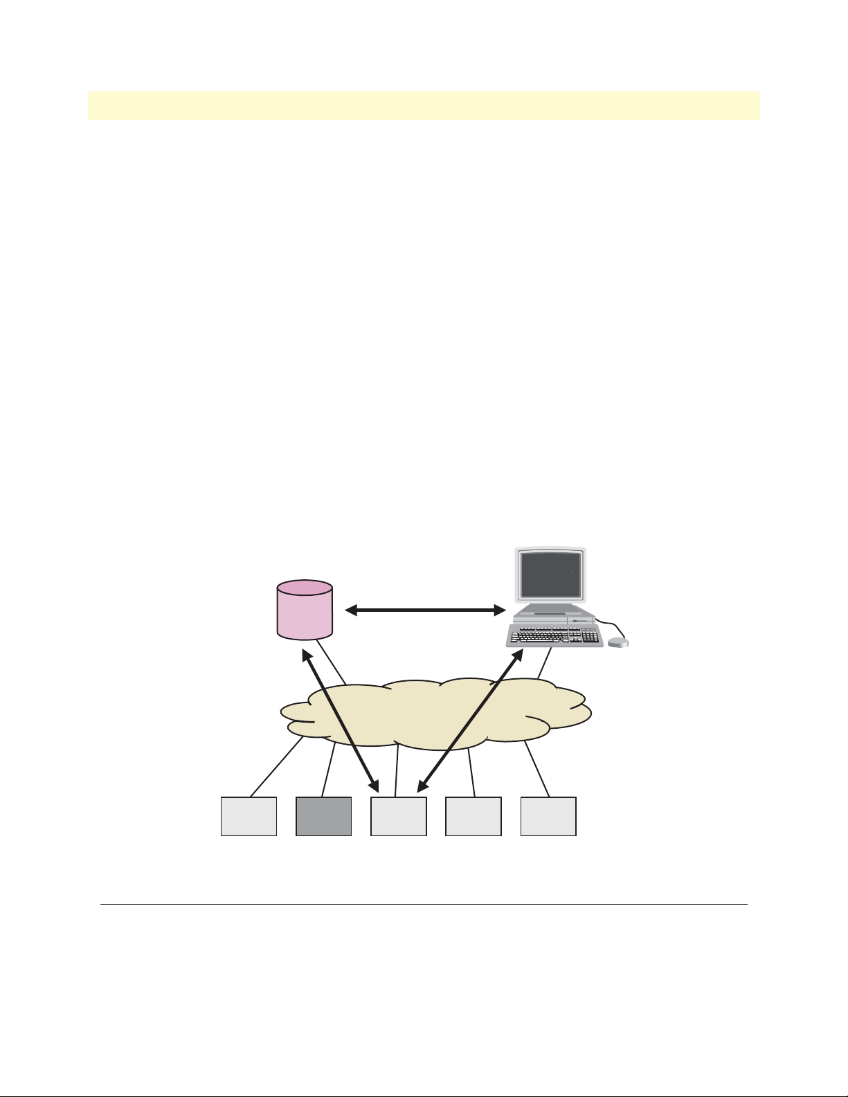
IPLink Software Configuration Guide 1 • System overview
An IPLink software build is a binary image file. It is usually divided into several checksum-protected files to
improve download efficiency and security. The download to the IPLink is handled in sequence by using a
download batchfile. Refer to chapter 6, “System image handling” on page 57 for details on IPLink software
image downloads.
In addition to the actual IPLink software images there are several additional embedded software components
that you will encounter:
• The boot loader is a “mini” application that performs basic system checks and starts IPLink software applica-
tion. It also provides minimal network services, allowing the IPLink to be accessed and upgraded over the
network even if IPLink software application should not start. The boot loader is installed in the factory and
requires no upgrading.
• The PMC loader initializes the PMC interface cards when mounted in IPLink devices. It checks the hard-
ware versions and determines whether compatible PMC drivers are available. The PMC loader may be
upgraded together with an IPLink software release.
• The PMC driver software performs the runtime tasks on the PMC interface cards mounted in IPLink
devices. The PMC drivers are interface card specific and also have build numbers. Refer to the IPLink software release notes for PMC driver software compatibility. The PMC drivers may be upgraded together with
an IPLink software release or they can be downloaded individually onto the device’s flash memory
file system.
Configuration Server
Network file system access
SNMP, Telnet
TFTP
WAN
2802 2803
Figure 3. IPLink Management System
2821
2823 2835
IPLink Software management center tools
IPLink software provides two management interfaces:
Network Management System
• The Command Line Interface (CLI), which supports full online configuration and monitoring access for
the operator
IPLink Software management center tools 27
Page 28

IPLink Software Configuration Guide 1 • System overview
• The SNMP agent and MIB, with an emphasis on inventory and alarm management for integration in a
third-party Network Management System (NMS)
With the aid of configuration files and TFTP up and downloads, the IPLink devices can also be managed
offline using standard text editors and file systems.
A number of host-based management applications are available to facilitate generating, editing, and maintaining configuration files. Tools are also available for integrating IPLink management into standard network management platforms such as HP OpenView.
IPLink Software management center tools 28
Page 29

Chapter 2 Configuration concepts
Chapter contents
Introduction..........................................................................................................................................................30
Contexts and Gateways .........................................................................................................................................31
Context ...........................................................................................................................................................31
Interfaces, Ports, and Bindings ..............................................................................................................................31
Interfaces ........................................................................................................................................................31
Ports and circuits ............................................................................................................................................31
Bindings .........................................................................................................................................................32
Profiles and Use commands...................................................................................................................................32
Profiles ............................................................................................................................................................32
Use Commands ..............................................................................................................................................32
29
Page 30
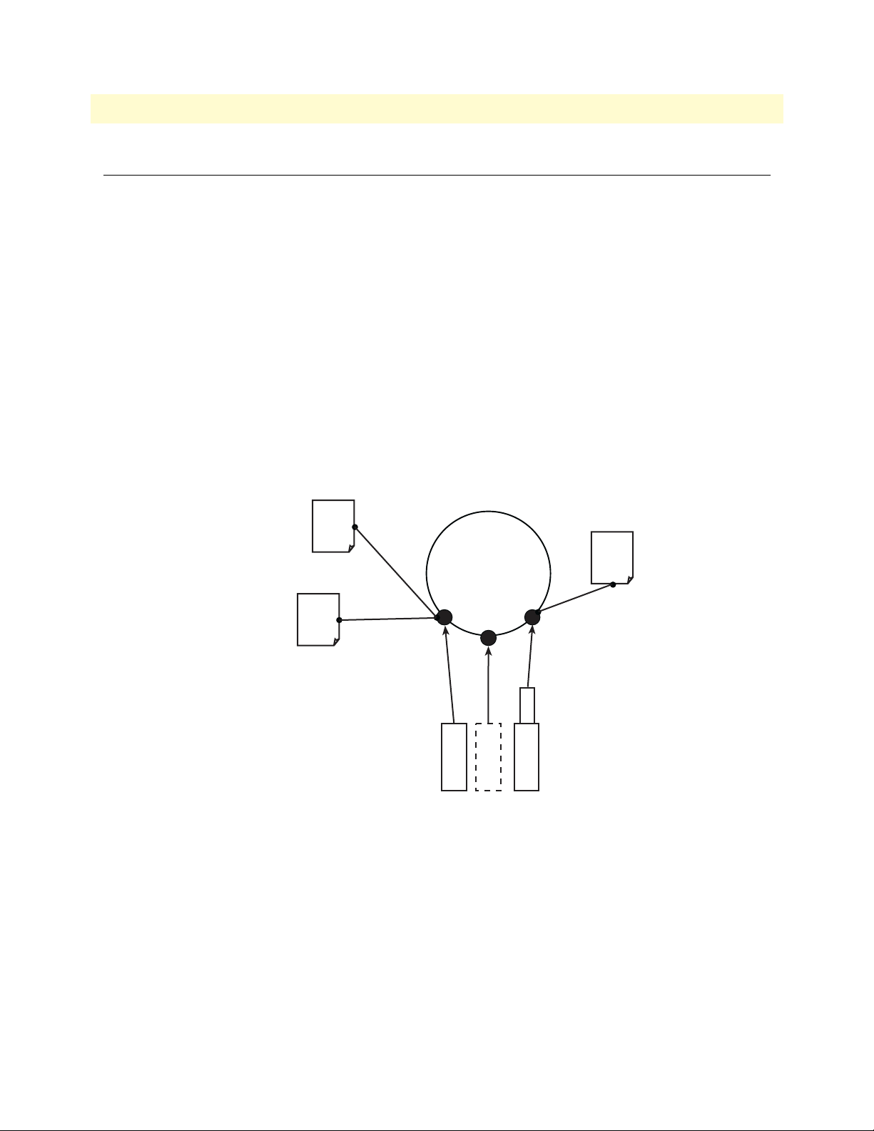
IPLink Software Configuration Guide 2 • Configuration concepts
Introduction
This chapter introduces basic IPLink software configuration concepts. A good understanding of these concepts
is vital for the configuration tasks explained in the remaining chapters of this guide.
Patton strongly recommends that you read through this chapter because it introduces the fundamental ideas
behind the structure of the command line interface. Once you understand and know this structure, you will
find it much more intuitive to navigate through the CLI and configure specific features.
This chapter includes the following sections:
• Contexts (see page 31)
• Interfaces, ports, and bindings (see page 31)
• Profiles and Use commands (see page 32)
Patton IPLink devices are multi-service network devices that offer high flexibility for the inter-working of circuit-switched and packet-routed networks and services. In order to consistently support a growing set of functions, protocols, and applications, IPLink software configuration is based on a number of abstract concepts
that represent the various IPLink software components.
NAPT
Context
Interfaces
Circuit
Ports
Profile
use command
ACL
Profile
bind command
Figure 4. Configuration concept overview
Context
IP
router
PVC
Ethernet
Serial
bind command
Service
Policy
Profile
use command
Figure 4 shows the various elements of a complete IPLink configuration. Each of these elements implements
one of the configuration concepts described in this chapter. The figure also shows the relationships and associations between the different elements. The relations are specified through bind (arrow) and use (bullet-lines)
commands. For example, you need bind commands to bind a physical port to a logical interface, and use commands to assign profiles to contexts.
The sections that follow refer to figure 4 on page 30 and describe the concepts and elements in
more detail.
Introduction 30
Page 31

IPLink Software Configuration Guide 2 • Configuration concepts
Contexts and Gateways
Context
An IPLink software context represents one specific networking technology or protocol, namely IP (Internet
Protocol). A context can be seen as virtual dedicated equipment within the IPLink. For example:
• An IP context contains the routing functions of the IPLink. It can be thought of as an embedded router
within the IPLink
The contexts are identified by a name and contain the configuration commands that are related to the technology
they represent. A separate configuration can be built by means of the context concept for newly supported network layer technologies without complicating the configuration methods of existing features. For example, as
bridging, ATM, or FR switching becomes available so a bridging, ATM, or FR context can be introduced.
Each context contains a number of interfaces, which build the connections to other IPLink software elements
and the outside world. Figure 4 on page 30 shows one context:
• one of type IP named router
This corresponds to the default configuration of all IPLink devices.
Note IPLink software currently supports only one instance of the IP context types.
Example
The IP context named router can contain static routes, RIP, and NAT configuration parameters.
Interfaces, Ports, and Bindings
Interfaces
The concept of an interface in IPLink software differs from that in traditional networking devices. Traditionally, the term interface is often synonymous with port or circuit, which are physical entities. In IPLink software
however, an interface is a logical construct that provides higher-layer protocol and service information, such as
layer 3 addressing. Interfaces are configured as part of a context, and are independent of physical ports and circuits. The decoupling of the interface from the physical layer entities enables many of the advanced features
offered by IPLink software.
In order for the higher-layer protocols to become active, you must associate an interface with a physical port or
circuit. This association is referred to as a binding in IPLink software. Refer to the “Bindings” section for more
information. In figure 4 on page 30, the IP context shows three interfaces. These interfaces are configured
within their context. The bindings shown in the figure are not present when the interfaces are configured; they
are configured later.
Ports and circuits
Ports and circuits in IPLink software represent the physical connectors and channels on the IPLink hardware.
The configuration of a port or circuit includes parameters for the physical and data link layer such as line
clocking, line code, framing and encapsulation formats or media access control. Before any higher-layer user
data can flow through a physical port or circuit, you must associate that port or circuit with an interface on a
context. This association is referred to as a binding. Refer to the “Bindings” section for more information.
Contexts and Gateways 31
Page 32

IPLink Software Configuration Guide 2 • Configuration concepts
Examples of IPLink ports are: 10Base-T Ethernet, Serial T1/E1, V.35, and X.21. Ports are numbered according
to the IPLink port numbering scheme. The port name corresponds to the label (or abbreviation) printed on
the hardware.
Example: Ethernet 0/1, Serial 0/0
Some ports may contain multiple circuits. For example, serial ports can contain one or more Frame Relay Permanent Virtual Circuits (PVC). If a port has one or more circuits configured, the individual circuits are bound
to interfaces on a context. The port itself may not be bound in that case.
Example: frame-relay pvc 112.
Figure 4 on page 30 shows three ports. Three ports are bound directly to an IP interface. One port has a single
circuit configured, which is bound to the IP context.
Bindings
Bindings form the association between circuits or ports and the interfaces configured on a context. No user
data can flow on a circuit or Ethernet port until some higher-layer service is configured and associated with it.
In the case of IP interfaces, bindings are configured statically in the port or circuit configuration. The binding
is created bottom-up, that is from the port to the interface.
Bindings from ports to IP interfaces are shown in figure 4 on page 30.
Profiles and Use commands
Profiles
Profiles provide configuration shortcuts. They contain specific settings that can be used in multiple contexts or
interfaces. This concept allows to avoid repetitions of groups of configuration commands that are the same for
multiple elements in a configuration.
Profiles used in the IP are shown in figure 4 on page 30.
Use Commands
Use commands form the association between profiles and contexts, or interfaces. For example, when a profile is
used in a context, all the configuration settings in that profile become active within the context.
Profiles and Use commands 32
Page 33

Chapter 3 Command line interface (CLI)
Chapter contents
Introduction..........................................................................................................................................................34
Command modes..................................................................................................................................................34
CLI prompt ....................................................................................................................................................34
Navigating the CLI .........................................................................................................................................35
Initial mode ..............................................................................................................................................35
System changes .........................................................................................................................................35
Configuration ...........................................................................................................................................35
Changing Modes .......................................................................................................................................35
Command editing .................................................................................................................................................35
Command help ...............................................................................................................................................35
The No form ..................................................................................................................................................35
Command defaults—returning parameters to default values ...........................................................................36
Command completion ....................................................................................................................................36
Command history ...........................................................................................................................................36
Command Editing Shortcuts ..........................................................................................................................36
33
Page 34

IPLink Software Configuration Guide 3 • Command line interface (CLI)
Introduction
The primary user interface to IPLink software is the command line interface (CLI). You can access the CLI via
the IPLink console port or through a Telnet session. The CLI lets you configure the complete IPLink software
functionality, as opposed to the SNMP and HTTP management interfaces that offer a more limited subset of
the functions. You can enter CLI commands online or as a configuration script in the form of a text file. The
CLI also includes monitoring and debugging commands. CLI commands are simple strings of keywords and
user-specified arguments.
This chapter gives an overview of the CLI and the basic features that allow you to navigate the CLI and edit
commands effectively. The following topics are covered:
• Command Modes
• Command Editing (see page 35)
Command modes
The CLI is composed of modes. There are two mode groups: the exec mode group and the configuration mode
group. Within the exec mode group there are two modes: operator exec and administrator exec. The configuration mode group contains all of the remaining modes. A command mode is an environment within which a
group of related commands is valid. All commands are mode-specific, and certain commands are valid in more
than one mode. A command mode provides command line completion and context help within the mode. The
command modes are organized hierarchically. The current working mode is indicated by the CLI prompt.
Appendix B, “Mode summary” on page 309 contains a detailed overview of all command modes, and
appendix C, “Command summary” on page 313 describes the commands that are valid in each mode.
CLI prompt
For interactive (online) sessions, the system prompt is displayed as:
nodename>
In the operator exec mode, the system prompt is displayed as:
nodename#
In the administrator exec mode and in the different configuration modes, the system prompt is displayed as:
nodename(mode)[name]#
Where:
• nodename is the currently configured name of the IPLink, the IP address or the hardware type of the device
that is being configured
• mode is a string indicating the current configuration mode, if applicable.
• name is the name of the instance of the current configuration mode
Example: the prompt in
IPLink(radius)[deepblue]#
radius-client mode, assuming the nodename IPLink and the instance deepblue is:
The CLI commands used to enter each mode and the system prompt that is displayed when you are working
in each mode is summarized in appendix B, “Mode summary” on page 309.
Introduction 34
Page 35

IPLink Software Configuration Guide 3 • Command line interface (CLI)
Navigating the CLI
Initial mode
When you initiate a session, you can log in with operator or administrator privileges. Whichever login you use,
the CLI is always set to operator exec (non-privileged exec) mode by default upon startup. This mode allows
you to examine the state of the system using a subset of the available CLI commands.
System changes
In order to make changes to the system, the administrator exec (privileged exec) mode must be entered. The
enable user interface command is used for this purpose (the enable command is only accessible if you are
logged in as an administrator). Once in administrator exec mode, all of the system commands are available to
you.
Configuration
To make configuration changes, the configuration mode must be entered by using the
configure command in
the administrator exec mode. After doing that, other configuration modes are accessible, as diagrammed in the
overview in figure 4 on page 30.
Changing Modes
The
exit command moves the user up one level in the mode hierarchy (the same command works in any of
configuration modes). For example, when in pvc configuration mode, typing
exit will take you to framerelay
configuration mode.
exit command terminates a CLI session when typed from the operator exec mode.
The
A session can also be terminated by using the
logout command within any mode.
Command editing
Command help
To see a list of all CLI commands available within a mode, type a question mark <?> or the <tab> key at the
system prompt in the mode of interest. A list of all available commands is displayed. Commands that have
become available in the current mode are displayed at the bottom of the list, separated by a line. Commands
from higher hierarchy levels are listed at the top.
You can also type the question mark or the <tab> key while in the middle of entering a command. Doing so
displays the list of allowed choices for the current keyword in the command. Liberal use of the question mark
functionality is an easy and effective way to explore the command syntax.
The No form
Almost every command supports the keyword
function or “deletes” a command from the configuration. For example, to enable the Session Router trace tool,
enter the command
mand
no debug session-router.
debug session-router. To subsequently disable the Session Router trace, enter the com-
no. Typing the no keyword in front of a command disables the
Command editing 35
Page 36

IPLink Software Configuration Guide 3 • Command line interface (CLI)
Command defaults—returning parameters to default values
The parameters of certain commands are set to their default value simply by omitting the parameter.
For example:
• sntp-client local-port 220—Sets the UDP port used by the SNTP client to 220
• sntp-client local-port—Sets the UDP port used by the SNTP client back to its default setting of 123
The other examples of such commands are:
sntp-client operating-mode sntp-client anycast-address sntp-client local-port
sntp-client poll-interval penalty-box-time sntp-client gmt-offset
server-timeout timeout domain
Command completion
You can use the <tab> key in any mode to carry out command completion. Partially typing a command name
and pressing the <tab> key causes the command to be displayed in full up to the point where a further choice
has to be made. For example, rather than typing
configure, typing conf and pressing the <tab> key causes the
CLI to complete the command at the prompt. If the number of characters is not sufficient to uniquely identify
the command, the CLI will provide a list with all commands starting with the typed characters. For example, if
you enter the string co in the configure mode and press <tab>, the selections
configure, copy, and context are
displayed.
Command history
IPLink software maintains a list of previously entered commands that you can go through by pressing the <uparrow> and <down-arrow> keys, and then pressing <enter> to enter the command.
The show history command displays a list of the commands you can go through by using the arrow keys.
Command Editing Shortcuts
IPLink software CLI provides a number of Emacs-style command shortcuts that facilitate editing of the command line. Command editing shortcuts are summarized in table 4 on page 36. The syntax <Ctrl>-<p> means
press the <p> key while holding down the keyboard’s control key (sometimes labeled Control, Ctl, or Ctrl,
depending on the keyboard and operating system of your computer).
<Esc>-<f> is handled differently; press and release the escape key (often labeled Esc on many keyboards) and
then press the <f> key.
Table 4. Command edit shortcuts
Keyboard Description
<Ctrl>-<p> or <up-arrow> Recall previous command in the command history.
<Ctrl>-<p> or <up-arrow> Recall next command in the command history.
<Ctrl>-<p> or <up-arrow> Move cursor forward one character.
<Ctrl>-<p> or <up-arrow> Move cursor backward one character.
Command editing 36
Page 37

IPLink Software Configuration Guide 3 • Command line interface (CLI)
Table 4. Command edit shortcuts (Continued)
Keyboard Description
<Esc>-<f> Move cursor forward one word.
<Esc>-<b> Move cursor backward one word.
<Ctrl>-<a> Move cursor to beginning of line.
<Ctrl>-<e> Move cursor to end of line.
<Ctrl>-<k> Delete to end of line.
<Ctrl>-<u> Delete to beginning of line.
<Ctrl>-<d> Delete character.
<Esc>-<d> Delete word.
<Ctrl>-<c> Quit editing the current line.
<Ctrl>-<l> Refresh (redraw) the display.
<Ctrl>-<t> Transpose characters.
<Ctrl>-<v> Insert a code to indicate to the system that the keystroke immediately fol-
lowing should be treated as normal text, not a CLI command.
For example, pressing the question mark <?> character in the CLI prints a
list of possible tokens. If you want to use the ? in a configuration command, e.g. to enter a regular expression, press Ctrl-v immediately followed by the question mark <?>.
Command editing 37
Page 38

Chapter 4 Accessing the CLI
Chapter contents
Introduction..........................................................................................................................................................39
Accessing the IPLink software CLI task list............................................................................................................39
Accessing via the console port .........................................................................................................................40
Console port procedure .............................................................................................................................40
Accessing via a Telnet session ..........................................................................................................................41
Telnet Procedure .......................................................................................................................................41
Using an alternate TCP listening port for the Telnet server .............................................................................42
Disabling the Telnet server .............................................................................................................................42
Logging onto the IPLink software ...................................................................................................................42
Selecting a secure password .............................................................................................................................43
Password encryption .......................................................................................................................................43
Configure operators and administrators ..........................................................................................................44
Password encryption .................................................................................................................................44
Factory preset administrator account .........................................................................................................44
Creating an operator account ....................................................................................................................44
Creating an administrator account ............................................................................................................45
Displaying the CLI version .............................................................................................................................45
Displaying account information ......................................................................................................................46
Switching to another account ..........................................................................................................................46
Checking identity and connected users ...........................................................................................................47
Command index numbers ..............................................................................................................................47
Ending a Telnet or console port session ..........................................................................................................49
Hidden commands in .cfg configuration files ..................................................................................................49
38
Page 39

IPLink Software Configuration Guide 4 • Accessing the CLI
Introduction
IPLink products are designed for remote management and volume deployment. The management and configuration of IPLink devices is therefore based on IP network connectivity. Once an IPLink is connected to, and
addressable in, an IP network, you can remotely perform all configuration, management, and maintenance
tasks.
This chapter describes the procedures for entering IPLink software commands via the command line interface
(CLI), to obtain help, to change operator mode, and to terminate a session. You can access an IPLink as follows:
• Directly, via the console port (by using a terminal directly connected to an IPLink)
• Remotely, via the IP network (by using a Telnet application)
The ports available for connection and their labels for each IPLink model are shown in the getting started
guide that came with your IPLink system.
Remember that the CLI supports a command history and command completion. By scrolling with the up and
down arrow keys, you can find many of your previously entered commands. Another timesaving tool is command completion. If you type part of a command and then press the <tab> key, the IPLink software shell will
present you with either the remaining portion of the command or a list of possible commands. These features
are described in chapter 3, “Command line interface (CLI)” on page 33. The telnet server can be disabled
if desired.
Although IPLink software supports concurrent sessions via Telnet
or the console port, we do not recommend working with more
IMPORTANT
than one session to configure a specific IPLink.
Accessing the IPLink software CLI task list
The following sections describe the basic tasks involved in accessing the IPLink software command line interface. Depending on your application scenario, some tasks are mandatory while others could be optional.
• Accessing via the console port (see page 40)
• Accessing via a Telnet session (see page 41)
• Using an alternate TCP listening port for the Telnet server (see page 42)
• Disabling the Telnet server (see page 42)
• Logging on to the IPLink software (see page 42)
• Selecting a secure password (see page 43)
• Configuring operators and administrators (see page 43)
• Displaying the CLI version (see page 45)
• Displaying account information (see page 46)
• Switching to another log-in account (see page 46)
• Checking identity and connected users (see page 47)
• Ending a Telnet or console port session (see page 49)
Introduction 39
Page 40

IPLink Software Configuration Guide 4 • Accessing the CLI
Accessing via the console port
To access an IPLink via its console port, the host computer must be connected directly to the console port
(labeled CONSOLE) with a serial cable (see figure 5). The host must use a terminal emulation application that
supports serial interface communication.
Serial interface
Host
Figure 5. Setup for initial configuration via the console port
Note You do not need to configure IP settings if you access the IPLink via the con-
Console
Node
Node
sole port.
Console port procedure
Before using the CLI to enter configuration commands, do the following:
1. Set up the hardware as described in the getting started guide that came with your IPLink system.
2. Configure your serial terminal for 9600 baud, 8 data bits, no parity, 1 start bit, 1 stop bit, and no flow control.
3. Connect the serial terminal to your IPLink. Use a serial cable according to Appendix A of the getting
started guide included with your IPLink device.
4. Power on your IPLink. A series of boot messages are displayed on the terminal screen. At the end of the
boot sequence, press the <return> key and the login screen will be displayed.
5. Proceed with logging in.
Accessing the IPLink software CLI task list 40
Page 41

IPLink Software Configuration Guide 4 • Accessing the CLI
Accessing via a Telnet session
This is the most commonly used method for connecting to an IPLink. The Telnet host accesses the IPLink via
its network interface. A host can be connected directly to the ETH 1 port (LAN) with a crossover cable (see
figure 6, part A) or through an Ethernet hub with two straight cables (see figure 6, part B).
Network
A
Host
B
Host
Interface
Network
Interface
Crossover Cable
Hub
Straight Cables
ETH 0/1
(LAN)
ETH 0/1
(LAN)
Node
Node
Node
Node
Figure 6. Setup for initial configuration via an Ethernet port
Note If the IP configuration of the Ethernet port (LAN port) is not known or is
incorrectly configured, you will have to use the console interface.
The host must have a valid IP address configured in the same subnet as the IPLink. Table 5 lists the default IP
address and network mask of the Ethernet ports of the IPLink.
Table 5. Factory default IP address and network mask configuration
Item IP Address Network Mask
WAN interface Ethernet 0 (ETH 0/0) DHCP client DHCP client
LAN interface Ethernet 1 (ETH 0/1) 192.168.1.1 255.255.255.0
DHCP server address range 192.168.1.10–192.168.1.99 255.255.255.0
Note The DHCP server is running on the ETH 0/1. All Ethernet ports are pre-
configured and active.
Note The default IP addresses listed in table 5 apply to an operating scenario com-
patible with the factory configured settings of the IPLink. If your operating
requirements are significantly different, your IPLink may have different
default IP addresses. Check IPLink software release notes for more details.
Telnet Procedure
Before you begin to use the CLI to input configuration commands, do the following:
1. Set up the IPLink as described in the Quick Start Guide included with your IPLink device.
2. Connect the host (PC) or hub to the ETH 1 (LAN) port of your IPLink with crossover or straight-thru
cables, according to Appendix A of the getting started guide included with your IPLink device.
Accessing the IPLink software CLI task list 41
Page 42

IPLink Software Configuration Guide 4 • Accessing the CLI
3. Power on your IPLink and wait until the Run LED lights.
4. Set your PC is set to DHCP.
5. Open a Telnet session to the ETH 1 (LAN) port with the IP address 192.168.1.1 of your IPLink.
6. Proceed with logging in.
Using an alternate TCP listening port for the Telnet server
The following command defines an alternate listening port for the telnet server.
Mode: Configure
Step Command Purpose
1 [name](cfg)# terminal telnet port <port> Uses TCP port <port> for accepting
telnet connections
Disabling the Telnet server
The telnet server can be disabled using the following command.
Mode: Configure
Step Command Purpose
1 [name](cfg)# no terminal telnet Disables the telnet server
Logging onto the IPLink software
Accessing your IPLink via the local console port or via a Telnet session opens a login screen. The following
description of the login process is based on a Telnet session scenario but is identical to that used when accessing
via the local console port.
The opening Telnet screen you see resembles that shown in figure 7. The window header bar shows the IP
address of the target IPLink.
A factory preset administrator account with name administrator and an empty password is programmed into
the IPLink software at the factory. For that reason, use the name administrator after the login prompt and simply press the <enter> key after the password prompt.
Figure 7. Login display
Accessing the IPLink software CLI task list 42
Page 43

IPLink Software Configuration Guide 4 • Accessing the CLI
Upon logging in you are in operator execution mode, indicated by the “>” as command line prompt. Now you
can enter system commands.
Note Details on screen in figure 7, such as the IP address in the system prompt
and window header bar, may be different on your IPLink device.
You are responsible for creating a new administrator account to
maintain system security. Patton Electronics accepts no responsi-
IMPORTANT
bility for losses or damage caused by loss or misuse of passwords. Please read the following sections to secure your network
equipment properly.
Selecting a secure password
It is not uncommon for someone to try to break into (often referred to as hacking) a network device. The network administrator should do everything possible to make the network secure. Carefully read the questions
below and see if any applies to you:
• Do your passwords consist of a pet’s name, birthdays or names of friends or family members, your license
plate number, social security number, favorite number, color, flower, animal, and so on?
• Do you use the same password repeatedly? (Example: Your ATM PIN, cell phone voice mail, house alarm
setting code, etc.)
• Could your password or a portion thereof be found in the dictionary?
• Is your password less than six characters long?
To prevent unauthorized access, you should select passwords that are not dictionary words or any of the abovementioned examples. Every password should be at least 6 characters long and include at least one capital letter,
one number, and one lowercase letter.
A good example of a password is: 3Bmshtr
You are probably asking yourself, “How am I going to remember that?” It’s easy, the password above is an acronym taken from: “three blind mice, see how they run.” Making a good password is that easy—but please, don’t
use the above example password for your IPLink device!
Password encryption
Password encryption is the same for all passwords: administrator/operator accounts, PPP, DynDNS, and so
on). You can enter the password in two formats:
• Plain text, for example: secretpassword
• Encrypted, for example: HUAvCYeILWZz33hQvS0IEpQ==encrypted
When executing the command
mat. A password is encrypted by entering it in plain text, then executing the
You may also store it permanently into the startup-config by using the command
startup-config
.
show running-config, the passwords are always displayed in encrypted for-
show running-config command.
copy running-config
Accessing the IPLink software CLI task list 43
Page 44

IPLink Software Configuration Guide 4 • Accessing the CLI
Configure operators and administrators
To secure the system, as well as to enable remote access to the system, you must create operator and administrator login accounts. These accounts are valid system-wide. Operators and administrators can log in to the
IPLink software via the console or through Telnet.
Note Only administrators are allowed to create new administrator and operator
accounts.
Password encryption
Unencrypted passwords can be stolen by hackers using protocol analyzers to scan packets or by examining the
configuration file—to protect against that type of theft, IPLink software encrypts passwords by default.
Encryption prevents the password from being readable in the configuration file.
Note The password encryption feature prevents unauthorized users from getting
passwords by looking at the configuration file. Other types of encryption
that can be configured in the IPLink software (ESP, VPN, and IPsec) protect
data transmitted from the IPLink device.
The procedure for password encryption is the same for all the passwords (administrator/operator accounts,
PPP, DynDNS, RADIUS). Passwords can be entered in as follows:
• Plain text
• Encrypted text (for example, the password mypassword always appears in encrypted form as
HUAvCYeILWZz3hQvS0IEpQ== encrypted when doing a
The command
show running-config always displays the passwords in encrypted format. To encrypt a pass-
show command)
word, enter the password in plain format and retrieve the encrypted format from the running-config or store it
permanently into the startup-config (with the command
copy running-config startup-config).
Factory preset administrator account
At the beginning of setup, IPLink software contains a factory preset administrator account with the name
administrator and an empty password. After adding a new administrator account, the factory preset administrator account is automatically deleted and only the newly created administrator account is available. You can create more than one administrator account, but there has to be at least one administrator account defined. If, for
some reason, the last administrator account is deleted, IPLink software automatically recreates the factory preset administrator account with the name administrator and an empty password.
Creating an operator account
Operators do not have the privileges to run the
enable command and therefore cannot modify the system
configuration. Operators can view partial system information.
Creating a new operator account is described in the following procedure:
Mode: Operator execution
Step Command Purpose
1 node>enable Enters administration execution mode
2 node#configure Enters configuration mode
Accessing the IPLink software CLI task list 44
Page 45

IPLink Software Configuration Guide 4 • Accessing the CLI
Step Command Purpose
3 node(cfg)# operator name password password Creates a new operator account name and
password password
4 copy running-config startup-config Saves the change made to the running config-
uration of the IPLink, so that it will be used following a reload
Example: Create an operator account
The following example shows how to add a new operator account with a login name support and a matching
password of s4DF&qw. The changed configuration is then saved.
IPLink>enable
IPLink#configure
IPLink(cfg)#operator support password s4DF&qw
IPLink(cfg)#copy running-config startup-config
Creating an administrator account
Administrators can run the
enable command and access additional information within the IPLink software
configuration modes. Therefore administrators can modify the system configuration, as well as view all relevant
system information.
Creating a new administrator account is described in the following procedure:
Mode: Operator execution
Step Command Purpose
1 node>enable Enters administration execution mode
2 node#configure Enters configuration mode
3 node(cfg)# administrator name password password Creates a new administrator account
name and password password
4 node(cfg)#copy running-config startup-config Permanently stores the new administrator
account parameters.
Example: Create an administrator account
The following example shows how to add a new administrator account with a login name super and a matching
password Gh3*Ke4h.
IPLink>enable
IPLink#configure
IPLink(cfg)#administrator super password Gh3*Ke4h
IPLink(cfg)#copy running-config startup-config
Displaying the CLI version
This procedure displays the version of the currently running IPLink software CLI.
Accessing the IPLink software CLI task list 45
Page 46

IPLink Software Configuration Guide 4 • Accessing the CLI
Mode: Operator execution
Step Command Purpose
1 node>show version cli Displays the CLI version
Example: Displaying the CLI version
The following example shows how to display the version of the current running IPLink software CLI on your
device, if you start from the operator execution mode.
IPLink>show version cli
CLI version : 3.00
Displaying account information
You can use the
show command in the IPLink software to display information about existing administrator
and operator accounts. This command is not available for an operator account.
The following procedure describes how to display account information:
Mode: Administrator execution
Step Command Purpose
1 node#show accounts Displays the currently-configured administrator and operator
accounts
Example: Display account information
The following example shows how to display information about existing administrator and operator accounts.
IPLink#show accounts
administrator accounts:
super
operator accounts:
support
Switching to another account
A user can use the
a user can change from his current account to another existing account ‘name’. After executing
su command to switch from one user account to working in another. With this command,
su with the
account name to which the user wants to change as argument, he must enter the password of the particular
account to get privileged access.
Mode: Administrator or operator execution
Step Command Purpose
1 node>su account-name Changes to the user account account-name.
Example: Switching to another account
The following example shows how to change from your current user account to an administrator account,
starting from the operator execution mode. In the example below the
who command is used to check the
identity within both accounts
Accessing the IPLink software CLI task list 46
Page 47

IPLink Software Configuration Guide 4 • Accessing the CLI
login: support
password: <password>
IPLink>who
You are operator support
IPLink>su super
Enter password: <password>
IPLink>who
You are administrator super
Checking identity and connected users
The
who command displays who is logged in or gives more detailed information about users and process
states. Depending on the execution mode, the command displays varying information. In administrator execution mode, the command output is more detailed and shows information about the ID, user name, state, idle
time, and location. In operator execution mode, only the user name being used at the moment is reported,
which helps checking the identity.
Mode: Administrator or operator execution
Step Command Purpose
1 node#who Shows more detailed information about the users ID, name, state, idle time and
location
or
node>who Shows the user login identity
Example: Checking identity and connected users
The following example shows how to report who is logged in or more detailed information about users and
process states, depending on the execution mode in which you are working.
Used in administrator execution mode:
IPLink#who
ID User name State Idle Location
* 0 administrator exec 00:00:00 172.16.224.44:1160
1 support exec 00:01:56 172.16.224.44:1165
Note The “*” character identifies the user executing the who command. ID repre-
sents the ID of the account. State represents the actual running condition of
the user, which can be logout, login, exec, or config.
Used in operator execution mode:
IPLink>who
You are operator support
Command index numbers
A command index number (indicated by the boldface 1, 2, and 3 index numbers in the example below) indicates the position of a command in a list of commands (that is, a command with index 1 will appear higher in
the configuration file than one with index 3).
192.168.1.1(pf-prov)[testpro]#show running-config
Accessing the IPLink software CLI task list 47
Page 48

IPLink Software Configuration Guide 4 • Accessing the CLI
...
profile provisioning testpro
location 1 tftp://10.10.1.2/test1.cfg
location 2 tftp://10.10.1.2/test2.cfg
location 3 tftp://10.10.1.2/test3.cfg
...
The following command has index numbers:
location
•
These commands always have index numbers in the running-config. However, entering the index is optional.
If you enter such a command with an index, it is inserted into list at the position defined by the index. If you
enter such a command without an index, it is placed at the bottom of the list. Also, you can change a commands position in a listing (moving it up or down in the list) by changing its index number.
Example 1: Moving the test1.cfg from position 1 in the list to position 3.
Listing before changing the location index number:
profile provisioning testpro
location 1 tftp://10.10.1.2/test1.cfg
location 2 tftp://10.10.1.2/test2.cfg
location 3 tftp://10.10.1.2/test3.cfg
...
Listing after changing index number:
192.168.1.1(pf-prov)[testpro]#location 1 after 3
192.168.1.1(pf-prov)[testpro]#show running-config
...
profile provisioning testpro
location 1 tftp://10.10.1.2/test2.cfg
location 2 tftp://10.10.1.2/test3.cfg
location 3 tftp://10.10.1.2/test1.cfg
...
Note The IPLink software automatically renumbered the succeeding indexes after
location 1 became location 3.
Accessing the IPLink software CLI task list 48
Page 49

IPLink Software Configuration Guide 4 • Accessing the CLI
Ending a Telnet or console port session
Use the
sion. To confirm the
logout command in the operator or administration execution mode to end a Telnet or console port ses-
logout command, you must enter yes on the dialog line as shown in the example below.
Mode: Operator execution
Step Command Purpose
1 node>logout Terminates the session after a confirmation by the user.
Example: End a Telnet or console port session
The following example shows how to terminate a session from the administrator execution configuration
mode.
IPLink>logout
Press 'yes' to logout, 'no' to cancel :
After confirming the dialog with “yes”, the Telnet session to the IPLink is terminated and the Telnet application window on your host closes.
Note Using the command exit in the operator execution mode also terminates a
Telnet or console port session, but without any confirmation dialog.
Hidden commands in .cfg configuration files
The command
cli config defaults turns it on, no cli config defaults turns it off. It is turned off by default.
When enabled, commands that are normally hidden will be displayed. Typically these commands comprise
well-known standard default values, which is why they are hidden by default to reduce the clutter in a displayed configuration file.
Accessing the IPLink software CLI task list 49
Page 50

Chapter 5 Establishing basic IP connectivity
Chapter contents
Introduction..........................................................................................................................................................51
IP context selection and basic interface configuration tasks.................................................................................... 51
Entering the IP context, creating IP interfaces and assigning an IP address .....................................................51
Defining IP Ethernet encapsulation and binding an IP interface to a physical port .........................................52
Activating a physical port ................................................................................................................................52
Displaying IP interface information ................................................................................................................53
Deleting IP interfaces ......................................................................................................................................54
Examples ...............................................................................................................................................................55
Setting up an IP interface on an Ethernet port ................................................................................................55
50
Page 51

IPLink Software Configuration Guide 5 • Establishing basic IP connectivity
Introduction
This chapter explains how to establish network-based connections to and from your IPLink using IP interfaces
and Ethernet ports. You can configure basic IP connectivity in the context IP and the subsidiary interface command modes. For a complete description of the IP context and interface configuration related commands
referred to in this chapter, see chapter 10, “IP context overview” on page 110, and chapter 11, “IP interface
configuration” on page 117.
The chapter includes the following sections:
• IP context selection and basic interface configuration tasks
• Examples (see page 55)
The predefined IP context in IPLink software contains the functionality of a classic IP router. Within the IP
context, packets are routed between IP interfaces according to the routing table. The following sections guide
you through all the steps necessary to establish network-based IP connectivity to and from your IPLink.
IP context selection and basic interface configuration tasks
The following are the basic tasks involved in configuring an IP context, the related interfaces, and ports:
• Entering the IP context, creating IP interfaces and assigning an IP address
• Defining IP Ethernet encapsulation and binding an IP interface to a physical port (see page 52)
• Activating the physical port (see page 52)
• Displaying IP interface information (see page 53)
• Deleting IP interfaces (see page 54)
After you have entered the IP context and performed the basic configuration tasks, it is possible to configure
additional protocols and services such as RIP, ICMP, and NAPT for your IP context.
Entering the IP context, creating IP interfaces and assigning an IP address
IPLink software application software running on your IPLink has a predefined IP context, which has to be
selected for the configuration procedure. An IP interface name can be any arbitrary string of not more than 25
characters. Use self-explanatory names for your IP interfaces which reflect their usage. Each IP interface needs
its explicit IP address and an appropriate net mask to be set.
Mode: Configure
Step Command Purpose
1 node(cfg)#context ip router Enters the predefined IP context configuration
mode.
2 node(ctx-ip)[router]#interface name Creates the new interface name, which repre-
sents an IP interface. This command also
places you in interface configuration mode
for the interface name you have just created.
3 node(if-ip)[name]#ipaddress ip-address netmask Sets the IP address ip-address and netmask
netmask for the interface name
Introduction 51
Page 52

IPLink Software Configuration Guide 5 • Establishing basic IP connectivity
Example: Enter IP context, create IP interfaces, and set IP address and netmask
The procedure below assumes that you want to create an IP interface named lan, with an IP address of
192.168.1.3 and a net mask of 255.255.255.0. Use the following commands in configuration mode to select
the IP context and create the IP interface.
IPLink(cfg)#context ip router
IPLink(ctx-ip)[router]#interface lan
IPLink(if-ip)[lan]#ipaddress 192.168.1.3 255.255.255.0
Defining IP Ethernet encapsulation and binding an IP interface to a physical port
Before an IP interface is accessible, you must define the IP Ethernet encapsulation for the related port. It is
assumed that you would like to define the IP Ethernet encapsulation for port port on slot slot. Before an IP
interface can be used, it needs to be bound to a physical port of your IPLink. The IPLink has one or more
expansion slots that can have one or more ports. Specifying a port unambiguously means that you must define
the slot in which it is located. It is assumed that you would like to bind the IP interface name to port port of
slot slot.
Mode: Configure
Step Command Purpose
1 node(cfg)#port ethernet slot port Enters port configuration mode and
selects the Ethernet port port on slot
slot, on which use the IP Ethernet
encapsulation and to which bind an IP
interface.
2 node(prt-eth)[slot/port]#encapsulation ip Sets IP Ethernet encapsulation for port
port on slot slot
3 node(prt-eth)[slot/port]#bind interface name router Binds the interface name to port port
on slot slot to the IP context named
router, which is the IP router context
Example: Define IP Ethernet encapsulation and bind IP interface to physical port
It is assumed that you would like to set the IP encapsulation for the Ethernet port 0 on slot 0 and bind the
already defined IP interface lan to the same physical port. Use the following commands in port Ethernet mode.
IPLink(ctx-ip)[router]#port ethernet 0 0
IPLink(prt-eth)[0/0]#encapsulation ip
IPLink(prt-eth)[0/0]#bind interface lan router
Activating a physical port
After completing all the settings for the IP interface, you must activate the physical port. The IPLink software
default status for any port is disabled. In IPLink software terminology, any port is in the shutdown state unless
it is activated by command.
IP context selection and basic interface configuration tasks 52
Page 53

IPLink Software Configuration Guide 5 • Establishing basic IP connectivity
Using the command show port ethernet slot port lists the actual status for the selected physical port. The following listing shows the port Ethernet information for port 0 on slot 0, which is in the shutdown state as indicated by the current state CLOSED.
IPLink(prt-eth)[0/1]#show port ethernet 0 0
Ethernet Configuration
-------------------------------------
Port : ethernet 0 0 0
State : CLOSED
MAC Address : 00:30:2B:00:1D:D4
Speed : 10Mbps
Duplex : Half
Encapsulation : ip
Binding : wan@router
Frame Format : standard
Default Service: 0
To activate a port for operation, you must remove the shutdown status of the port. That means you must
change the state of the port to OPENED. To activate a physical port, use the
no shutdown command in port
configuration mode.
Step Command Purpose
1 node(ctx-ip)[router]#port ethernet slot port Enters port configuration mode and selects the
Ethernet port port on slot slot, which is to be activated
2 node(prt-eth)[slot/port]#no shutdown Activates the physical port port on slot slot for
operation
Example: Activating the physical port
It is assumed that you would like to activate the physical port 0 on slot 0, for which you use the following commands in port configuration mode.
IPLink(cfg)#port ethernet 0 0
IPLink(prt-eth)[0/0]#no shutdown
At this point, your IPLink has a running IP interface on Ethernet port 0 on slot 0, which uses IP encapsulation.
Displaying IP interface information
You can display information for all the configured IP interfaces by using the
show command. The command
lists relevant information for every IP interface. The IP interfaces are identified by the name.
Mode: Configure
Step Command Purpose
1 node(cfg)#show ip interface Displays IP interface information
IP context selection and basic interface configuration tasks 53
Page 54

IPLink Software Configuration Guide 5 • Establishing basic IP connectivity
Example: List existing IP interfaces
You can display IP interface information by using the
show ip interface command in configuration mode. In
the following example, only the information available for IP interface lan is displayed. Depending on the number of defined IP interfaces, the output of the
IPLink(ctx-ip)[router]#show ip interface
…
-----------------------------------------------------------Context: router
Name: lan
IP Address: 192.168.1.3 255.255.255.0
P2P: point-to-point
MTU: 1500
ICMP router-discovery: enabled
ICMP redirect: send only
State: OPENED
Binding: ethernet 0 0 0/ethernet/ip
…
show ip interface command can be longer.
An easy way to list existing interfaces is by using the interface command followed by a “?” in the IP context
configuration mode, which creates a list of all the defined IP interfaces.
IPLink(cfg)#context ip router
IPLink(ctx-ip)[router]#interface <?>
<interface> New interface
external Existing interface
internal Existing interface
lan Existing interface
wan Existing interface
Deleting IP interfaces
It is often necessary to delete an existing interface in the IP context. The procedure described below assumes
that you would like to delete the IP interface name. Use the no argument to the
interface command as in the
following demonstration in IP context configuration mode.
Mode: Context IP
Step Command Purpose
1 node(ctx-ip)[router]#no interface name Deletes the existing IP interfaces name
Example: Delete IP interfaces
The procedure described below assumes that you would like to delete the IP interface named external. Use the
following commands in IP context mode.
1. List the existing interfaces:
IPLink(ctx-ip)[router]#interface <?>
<interface> New interface
external Existing interface
internal Existing interface
lan Existing interface
wan Existing interface
IP context selection and basic interface configuration tasks 54
Page 55

IPLink Software Configuration Guide 5 • Establishing basic IP connectivity
2. Delete the interfaces named external with the no interface command, with the interface name
as argument:
IPLink(ctx-ip)[router]#no interface external
3. List the interfaces again to check if the IP interface external has been deleted:
IPLink(ctx-ip)[router]#interface <?>
<interface> New interface
internal Existing interface
lan Existing interface
wan Existing interface
Examples
Setting up an IP interface on an Ethernet port
The following example shows all required configuration steps, which end in an activated IP interface on Ethernet port 0 on slot 0. Figure 8 shows the relation between the IP interface lan and the Ethernet port 0 on slot 0.
The configuration procedure below starts in the operator execution mode:
Context
IP
“router”
interface lan
bind command
Port
Ethernet
0 0
Port
Ethernet
0 1
Figure 8. Relation between IP Interface lan and Ethernet port 0 on slot 0
1. Select the context IP mode for the required IP interface configuration.
IPLink>enable
IPLink#configure
IPLink(cfg)#context ip router
2. Create a new interface lan, for which both the IP address and net mask are specified.
IPLink(ctx-ip)[router]#interface lan
IPLink(if-ip)[lan]#ipaddress 192.168.1.3 255.255.255.0
3. Select the Ethernet port 0 on slot 0; set the medium to 10 Mbps in half-duplex mode, and choose the IP
encapsulation for this port.
IPLink(if-ip)[lan]#port ethernet 0 0
IPLink(prt-eth)[0/0]#medium 10 half
Examples 55
Page 56

IPLink Software Configuration Guide 5 • Establishing basic IP connectivity
IPLink(prt-eth)[0/0]#encapsulation ip
4. Bind the interface lan you just defined to the Ethernet port, and then activate the port.
IPLink(prt-eth)[0/0]#bind interface lan router
IPLink(prt-eth)[0/0]#no shutdown
5. Store the configuration s
6. ettings in the startup configuration so as to be available after the next system reboot.
IPLink(prt-eth)[0/0]#copy running-config startup-config
Examples 56
Page 57

Chapter 6 System image handling
Chapter contents
Introduction..........................................................................................................................................................58
Memory regions in IPLink software.......................................................................................................................58
System image handling task list .............................................................................................................................60
Displaying system image information .............................................................................................................60
Copying system images from a network server to Flash memory .....................................................................61
Copying driver software from a network server to Flash memory ....................................................................62
Auto provisioning of firmware and configuration ..................................................................................................63
Boot procedure......................................................................................................................................................65
Bootloader.............................................................................................................................................................67
Start Bootloader ..............................................................................................................................................67
Start-up with factory configuration .................................................................................................................68
Load a new application image (IPLink software) via TFTP .............................................................................68
Load a new application image (IPLink software) via the serial link ..................................................................70
Factory configuration ............................................................................................................................................70
57
Page 58

IPLink Software Configuration Guide 6 • System image handling
Introduction
This chapter describes how to load, maintain, and update the various software images in the IPLink. The
IPLink software system software consists of the application image and the driver images. The images are stored
in persistent (non-volatile) memory. The application image is the software which actually operates the IPLink.
Driver images are used to operate the various optional PMC interface cards.
This chapter includes the following sections:
• Memory regions in IPLink software
• System image handling task list (see page 60)
• Boot procedure and bootloader (see page 65)
Note Section “System image handling task list” on page 60 describes the standard
way to upgrade the IPLink software. If you encounter problems that won’t
let you upgrade using the standard method, refer to section “Bootloader” on
page 67 as appropriate.
• Factory configuration (see page 70)
Patton IPLink devices are shipped with default system software which is stored in persistent memory. Along
with the default system software (application image and driver images), a factory configuration, factory-config,
has been loaded into the IPLink at the factory. This configuration file sets the initial basic operating parameters
of the IPLink, such as enabling the Ethernet ports, setting the default IP addresses and the DHCP server.
Other configuration files may be stored in the IPLink persistent memory. A configuration file is an ordered list
of commands. Some of the various configuration files are
• factory-config (read-only)
• startup-config
• running-config
• user-config1, user-config2, etc. (these are specific application configurations created by the user)
Backups of the configuration files can be stored on a remote trivial file transfer protocol (TFTP) server. The
remote tftp server must be accessible via one of the IPLink IP interfaces. Tftp cannot be used from the console
interface.
The following sections focus on IPLink software memory regions, as well as the software components you can
copy into the memory or move between a TFTP server and the memory of the IPLink. As IPLink software uses
a specific vocabulary in naming those software components, refer to appendix A, “Terms and definitions” on
304 to ensure that you understand the concepts.
Memory regions in IPLink software
The IPLink’s memory contains several logical regions and several physical regions as shown in figure 9 on
page 60, each separate from the other.
Note You will use a remote TFTP server for uploading and downloading the
application image, the driver images, and the various configuration files to
Introduction 58
Page 59

IPLink Software Configuration Guide 6 • System image handling
the IPLink. The command syntax in IPLink software requires you to prefix
the file path on the TFTP server with tftp: followed by the absolute file path.
You need to start from the root directory of the TFTP server.
The three physical regions of memory are the remote tftp server’s memory, the Volatile memories, and the Per-
sistent memory in the IPLink. The remote tftp server has one logical region, tftp:, which can contain various
configuration files and batch files for system software upgrade/download. Within the IPLink the Volatile phys-
ical region contains one logical region, system:, which is random access memory (RAM). When no power is
applied to the IPLink, the system: region contains no data, no configuration—nothing; it is volatile. The system: region contains the current running configuration, called running-config.
The third and last physical memory region is the Persistent portion. It has two logical regions called flash:
and nvram:.
• The logical region flash: stores the application image, the driver images and the bootloader image. These
images are not lost when the IPLink is powered off.
• The logical region nvram: stores the various configuration files. The factory default configuration file is
always present in nvram:, and can be restored as the running-config by pressing the reset button. For those
models that do not have a reset button, use the
copy command. The startup-config and user-specific con-
figurations are also stored in nvram:.
The factory configuration is read-only. It is contained in the logical region nvram: of the IPLink. It is used—if
no user-specific configuration is available—to start-up IPLink software with a minimal functionality. This configuration is named factory-config in IPLink software terminology.
On powering up an IPLink (or pressing the Reset button on applicable units) with no pre-configured user configuration files, the default factory-config file is also the startup-config and the running-config. Upon changing
any configuration parameters, the changes are made to the running-config in the system: region of the Volatile
memory. Unless these changes are copied into startup-config or another user-named configuration file, all configuration changes will be lost if the IPLink is powered down.
A dedicated user-specific configuration must be created and stored in the nvram: region of persistent memory.
In fact, you may create numerous user-specific configurations in the same IPLink, but if only one dedicated
user-specific config is required, you may save it in startup-config by using the
config
command. Any future time you restart the IPLink, it will use this saved configuration. In other words,
copy running-config startup-
the startup-config configuration file becomes your default operating configuration.
If you have created and saved numerous user-defined operating configuration files, you can change the startup
default configuration file simply by copying the selected config file into startup-config and rebooting
the IPLink.
Any configuration stored in logical region nvram: or system: can be copied to a remote server by using TFTP.
Operating configurations cannot be executed from the persistent memory, so the configuration used for operating the IPLink is copied into the volatile memory of the IPLink prior to normal operation. This procedure
takes place after the system bootstrap, where the application image (i.e. IPLink software) is started and a configuration must be available. Shortly before IPLink software has completed all startup processes, the configuration startup-config is copied from nvram: in persistent memory to the running-config configuration in system: in
volatile memory.
You can back up the running-config to nvram: or to a remote TFTP server with a user-defined name.
Memory regions in IPLink software 59
Page 60

IPLink Software Configuration Guide 6 • System image handling
Note When returning to the factory-config by using the copy factory-config star-
tup-config
command, all user-specific configurations saved in nvram:
remain even after reload.
Memory Regions in
Embedded Software
Remote (TFTP Server) Local (Intelligent Acess Device)
tftp:
• Configuration
Files
• Batchfiles for
System Image
download
Image / Microcode Download
Storing the current Running Configuration remotely
Configuration File Upload
flash:
• Application Image
• Bootloader Image
• Microcode Image
Configuration File Download
nvram
• Factory
Configuration
“factory-config”
(read-only)
• Startup
Configuration
“startup-config”
• User specific
Configuration
“user-config”
Storing the current Configuration locally
VolatilePersistent
:
Only on Startup to execute the
Startup or Factory Configuration
system:
• current Running
Configuration
“running-config”
Figure 9. IPLink memory regions logically defined in IPLink software
System image handling task list
To load and maintain system images, perform the tasks described in the following sections:
• Displaying system image information
• Copying system images from a network server to the Flash memory (see page 61)
• Copying the driver software from a network server to the Flash memory (see page 62)
Displaying system image information
This procedure displays information about system images and driver software
System image handling task list 60
Page 61

IPLink Software Configuration Guide 6 • System image handling
Mode: Administrator execution
Step Command Purpose
1 show version Lists the system software release version, information about optional interface
cards mounted in slots and other information that is the currently running system
software. If you have just completed a download of new system software from the
tftp server, you must execute the reload command in order to be running with the
new system software. This applies equally to driver software.
Example: Display system image information
The following example shows the information that is available for an IPLink 2800 series device with an
optional IC-4BRV interface card mounted in slot 2.
IPLink#show version
Product name : SN2803
Software Version : IPLink software R3.20 2006-02-02 H323 SIP FXS FXO
Supplier :
Provider :
Subscriber :
Information for Slot 0:
2803/K/EUI (Admin State: Application Started, Real State: Application Started)
Hardware Version : 4, 2
Serial number : 00A0BA01C47C
PLD Version : 0x00040103
Software Version : IPLink software R3.20 2006-02-02 H323 SIP FXS FXO
Copying system images from a network server to Flash memory
As mentioned previously, the system image file contains the application software that runs IPLink software; it
is loaded into the flash memory at the Patton Electronics Co. factory. Since most of the voice and data features
of the IPLink are defined and implemented in the application software, upgrading to a new release might be
necessary if you want to have additional voice and data features available. A new system image file must be
stored permanently into the flash memory of your IPLink to be present when booting the device.
Since the system image file is preloaded at the Patton Electronics Co. factory, you will have to download a new
IPLink software application software only if a major software upgrade is necessary or if recommended by Patton Electronics Co. Under normal circumstances, downloading a system image file should not be needed.
Downloading a new system image file means storing it permanently at a defined location within the IPLink
flash memory. To store the system image file, you must use a special download script file. This script file defines
how to handle the system image file and where to store it. You cannot download any system image file without
an appropriate script file.
Each line in the script file is a command for the CLI of your IPLink. To download a system image file, which
will replace the currently running IPLink software application software, a script file with only one command is
necessary.
System image handling task list 61
Page 62

IPLink Software Configuration Guide 6 • System image handling
Comment lines must have a hash character # in column one and can appear anywhere in the script file. Comment lines contain information for administrators or operators who maintain or use the script file.
The following example shows a script file used to download a system image and command line syntax definition file from a TFTP server.
# script file for system image download
# Patton Electronics Co. 2006-02-02
image.bin 1369474 21; ver 2803.1,2803.2;
cli.xml
+/flash/cli/spec.xml
*UÊDä
Note The script file includes a 32-bit CRC on the last line, displayed as four char-
acters when seen in an ordinary text editor. Do not delete the line containing
the CRC entry or the download will fail!
You can download the script file with the
copy command. The copy command source defines the TFTP path
to the script file and the target is set to use the script parser. After downloading the script file, the system image
file and command line syntax definition file download starts automatically.
Mode: Administrator execution
Step Command Purpose
1 node(cfg)# copy tftp://node-ip-address/b flash: Downloads the script file b from the TFTP
server at address node-ip-address and starts
the system image download process. This
progress is visualized with a counter, counting up from 0 to 100% according to the
downloaded amount of the file size for each
file that needs to be downloaded.
Example: Copy system images from a network server to the Flash memory
The following example shows how to download the driver software image file from the TFTP server at IP
address 172.16.36.80. The download is defined by a script file, which has to be downloaded first. After downloading the script file, the driver software image file is downloaded automatically.
IPLink>enable
IPLink#configure
IPLink(cfg)#copy tftp://172.16.36.80/2803/build22032/b flash:
Completed image download
Completed file download /flash/cli/spec.xml
IPLink(cfg)#
After the successful download, issue the reload command (in order to start the IPLink with the new software).
Copying driver software from a network server to Flash memory
Driver software images contain the driver software to be downloaded into hardware devices such as optional
interface cards.
System image handling task list 62
Page 63

IPLink Software Configuration Guide 6 • System image handling
Downloading a driver software image file means storing it permanently at a defined location within the flash
memory on the motherboard or in the non-volatile memory of an optional interface card. To download the
driver software image file, you must use a special download script file.
The following example shows a script file used to download a driver software image file from a TFTP server for
an IC-4BRV interface card.
# script file for driver software image download
# Patton Electronics Co. 2006-02-02
;
/Vx_R3.20_BUILD24028
+/flash/bin/pmc000216a6
4_—-
This script file defines how to handle the driver software image file and where to store it.
Note You cannot download any driver software image file without an appropriate
script file.
Mode: Administrator execution
Step Command Purpose
1 node(cfg)# copy tftp://node-ip-address/b flash: Downloads the script file b from the TFTP
server at address node-ip-address and
starts the driver software image download
process. This progress is visualized with a
counter, counting up from 0 to 100%
according to the downloaded amount of
the file size for each file that needs to be
downloaded.
Example: Copy driver software from a network server to the Flash memory
The following example shows how to download the driver software image file from the TFTP server at IP
address 172.16.36.80. The download is defined by a script file, which has to be downloaded first. After downloading the script file, the driver software image file is downloaded automatically.
IPLink>enable
IPLink#configure
IPLink(cfg)#copy tftp://172.16.36.80/build24028/b flash:
Completed file download /flash/bin/pmc000216a6
IPLink(cfg)#
Note In order for the newly downloaded driver software to be running, you must
execute the
reload command.
Auto provisioning of firmware and configuration
The new auto provisioning capability enables you to automatically distribute up-to-date configurations and
firmware to a large number of units using TFTP. It works as follows:
Auto provisioning of firmware and configuration 63
Page 64

IPLink Software Configuration Guide 6 • System image handling
The unit downloads a specific file from a TFTP server. If this file has changed since the last download, it is
stored and executed. If the file on the server did not change since the last download, no action is taken. If the
units are configured to do auto provisioning, a network operator can only update the firmware files on the
TFTP server, which automatically distributes it to all units. The “profile provisioning” configures this. Here’s
an example for firmware provisioning:
profile provisioning FIRMWARE
destination script
location 1 tftp://172.16.1.2/firmware/b
location 2 tftp://172.16.1.33/firmware/b
activation reload graceful
Explanation:
Step Command Purpose
1 [name] (pf-prov)[FIRMWARE]#destination script Chooses the unit’s script interpreter as des-
tination of the downloaded file. Use this
for firmware updates. Script files are the
b, b1, … files that come with each unit
firmware update.
2 [name] (pf-prov)[FIRMWARE]#location 1
tftp://172.16.1.2/firmware/b
3 [name] (pf-prov)[FIRMWARE]#location 2
tftp://172.16.1.33/firmware/b
4 [name] (pf-prov)[FIRMWARE]#activation reload
graceful
Specifies the location of the file to check
for changes.
Specifies alternate locations of the file. If
the first could not be contacted, the second is tried, and so on.
Specifies how the new firmware is to be
activated. Choose between immediate or
graceful reload.
Here’s an example for configuration provisioning:
profile provisioning CONFIG
destination configuration
location 1 tftp://tftp1.provider.net/configs/$(system.mac).cfg location 2 tftp://172.16.1.33/configs/$(system.mac).cfg activa-
tion reload graceful
Explanation:
Step Command Purpose
1 [name] (pf-prov)[CONFIG]#destination
configuration
2 [name] (pf-prov)[CONFIG]#location 1
tftp://tftp1.provider.net /configs/
$(system.mac).cfg
Auto provisioning of firmware and configuration 64
Chooses the unit’s startup-configuration as
destination of the downloaded file.
Specifies the location of the file to check
for changes. $(system.mac) is a placeholder for the unit’s MAC address of
ETH 0/0. Using host names instead of IP
addresses works only if DNS resolver is
enabled and configured.
Page 65

IPLink Software Configuration Guide 6 • System image handling
Step Command Purpose
3 [name] (pf-prov)[CONFIG]#location 2
tftp://172.16.1.33/configs/$(system.mac).cfg
4 [name] (pf-prov)[CONFIG]#activation reload
graceful
Specifies alternate locations of the file. If
the first could not be contacted, the second is tried, and so on.
Specifies how the new configuration
should be activated. Choose between
immediate or graceful reload.
Note the placeholder used in the file location. Placeholders can be used for each part of the location, be it
server address, path or filename. The following place holders are available:
• $(system.mac)—MAC address of ETH 0/0 (without “:” between the hexadecimal characters)
• $(system.serial)—serial number of the unit
• $(dhcp.66)—DHCP option 66 (TFTP server IP), as delivered by the DHCP server (only if DHCP
is enabled)
• $(dhcp.67)—DHCP option 67 (Boot file name), as delivered by the DHCP server (only if DHCP
is enabled)
To use and debug provisioning:
Step Command Purpose
1 [name] (cfg)provisioning execute FIRMWARE Executes the provisioning profile
FIRMWARE once
2 [name] (cfg)debug provisioning Enables debug output for all
provisioning operations
To continuously poll for firmware or configuration changes, use the
with the new
timer command as described below. Here’s how to do both firmware and configuration provi-
provisioning execute command together
sioning, with a polling interval of 10 minutes.
timer FIRMWARE_UPDATE now + 2 minutes every 10 minutes “provisioning execute FIRMWARE”
timer CONFIG_UPDATE now + 2 minutes every 10 minutes “provisioning execute CONFIG”
Boot procedure
During a normal boot procedure of an IPLink, the bootstrap application checks for an application image in the
persistent memory of the logical region nvram:. The application image is then executed, i.e. the IPLink software is started module by module. One of the last start-up tasks to finish in bringing up the entire system is
handling the operating configuration. The configuration startup-config is copied from the logical region nvram:
Boot procedure 65
Page 66

IPLink Software Configuration Guide 6 • System image handling
in nonvolatile memory to the logical region running-config in the volatile memory. The IPLink software now
uses the running-config to set up the operating configuration of the IPLink. Figure 10 illustrates the
boot procedure.
Power-On
Bootstrap Bootloader
pressed
System Button
released
Application
Application
Image
valid
start Software Modules
System Button
use startup-config use factory-config
invalid
released
System Up
Figure 10. Boot procedure
pressed
There are two situations during bootstrap when the bootloader takes control:
• “If the user has pressed the system button, it launches the bootloader, the bootstrap application checks the
status of the Reset button on the back panel of the IPLink.”
• If a valid application image is not available
The bootloader ensures that basic operations, network access, and downloads are possible in case of interrupted
or corrupted application image downloads.
After downloading an application image (that is, new system software/software upgrade), the bootloader
ensures that basic operations, network access, and downloads are possible in case of interrupted or corrupted
application image downloads. After downloading an application image, the bootstrap will only switch to the
Boot procedure 66
Page 67

IPLink Software Configuration Guide 6 • System image handling
newly loaded application image if it is valid. If it is not valid, the bootstrap still uses the application image
which existed prior to doing a software upgrade.
If the application image is valid, it is started and IPLink software is brought into operation module by module.
During this system initialization phase (when the message Press reset button to restore factory defaults... appears
on the console screen), the status of the reset button on the back panel of the IPLink is checked. If the button
has been pressed, the factory configuration is loaded into the volatile memory and is used to parameterize the
IPLink software. If the button has not been pressed, the startup configuration is loaded into the volatile memory and is used to parameterize the IPLink software.
Bootloader
Recall that the bootloader ensures that basic operations, network access, and downloads are possible in case of
interrupted or corrupted application image downloads. The IPLink Series comes with the RedBoot Bootloader.
It offers new features such as console access to the Bootloader and the capability for downloading application
images (e.g. IPLink software) via the serial link of the console.
Start Bootloader
To start the Bootloader, reload the system and press <ctrl>-<c> (when the message Press ^C to abort boot
script,... appears on the console screen). The follow prompt will be displayed:
RedBoot>
Type help to display an overview of the available commands.
Note If the cursor keys (up, down, left, right) are not working, use <ctrl>-<n> (for
up) and <ctrl>-<p> (for down) instead. Commands can be abbreviated as
long as they do not become ambiguous.
Bootloader 67
Page 68

IPLink Software Configuration Guide 6 • System image handling
Start-up with factory configuration
Step Command Purpose
1 RedBoot> fis load Copies the IPLink software application image from
the persistent memory (flash:) to the volatile memory (RAM) from where it will be executed.
2 RedBoot> go -s factory-config Starts the IPLink software application telling it to use
‘factory-config’ as startup configuration.
You can also start-up with any other configuration
available in the persistent memory (nvram:) by providing its name instead of ‘factory-config’.
Load a new application image (IPLink software) via TFTP
The following procedure downloads the application image (IPLink software) for the mainboard. See the note
below on how to download the respective CLI description file.
Step Command Purpose
1
optional
2
optional
3
optional
4 RedBoot> load -r -v -h host -b
5 RedBoot> fis delete -n 1 Deletes the first application image.
6 RedBoot> fis create Stores the downloaded application image to
7 RedBoot> fis list -l Checks whether the image has been success-
RedBoot> ip_address - l
local_ip_address [/mask_len]
RedBoot> ip_address -g gateway Sets the IP address of the default gateway.
RedBoot> ping -h tftp-server_ip_address Tests the connectivity to the TFTP server.
base_address file_name
Sets the IP address and subnet mask of the
Ethernet interface 0/0 which shall be used to
receive the new application image.
mask_len is the length of the network address
(or the number of 1’s within the subnet mask).
See Note below.
Downloads an application image into the volatile memory (RAM) from where the IPLink could
directly execute it.
host: IP address of the TFTP server
base_address: memory location where to store
the application image. Use the default address
0x1800100
file_name: path and name of the file on the
TFTP server. Note: use the image file that contains the whole application, not the image
parts.
Reply with ‘y’ to the confirmation request.
the permanent memory (flash:).
Reply with ‘y’ to the confirmation request.
fully stored, whether it is the desired Release
and Build, and whether it is valid.
Bootloader 68
Page 69

IPLink Software Configuration Guide 6 • System image handling
Step Command Purpose
8 RedBoot> go Starts the application image that was down-
loaded into the volatile memory (RAM).
Note With the Bootloader, only the Ethernet interface 0/0 is available. The Boot-
loader applies the IP address, subnet mask, and default gateway that were last
configured by the Bootloader itself or by another application (e.g. IPLink
software). If an application configured the Ethernet interface 0/0 to use
DHCP, the Bootloader will also use DHCP to learn the interface configuration. It can receive and apply the IP address, subnet mask, default gateway,
and default (TFTP) server (transmitted as basic DHCP information ‘Next
server IP address’).
Note This procedure does not download the respective CLI description file.
Download it after starting up IPLink software with the following command:
copy tftp://<tftp_server_address>/<server path>/b1 flash:
Example: Downloading and storing a new application image (IPLink software)
RedBoot> ip -l 172.16.40.98/19
RedBoot> ip -g 172.16.32.1
RedBoot> ping -h 172.16.32.100
Network PING - from 172.16.40.98 to 172.16.32.100
..........PING - received 10 of 10 expected
RedBoot> load -r -v -h 172.16.32.100 -b 0x1800100 /image.bin
Using default protocol (TFTP)
Raw file loaded 0x01800100-0x0199ca6b, 1689964 bytes, assumed entry at 0x01800100
RedBoot> fis delete -n 1
Delete image 1 - continue (y/n)? y
... Erase from 0x60030000-0x601cc974: ..........................
RedBoot> fis create
Use address 0x01800100, size 1684402 ? - continue (y/n)? y
... Erase from 0x60030000-0x601cb3ba: ..........................
... Program from 0x00011eec-0x00011ef4 at 0x60030000: .
... Program from 0x01800100-0x0199b4b2 at 0x60030008: ..........................
... Program from 0x00011eec-0x00011ef4 at 0x60030000: .
Image successfully written to flash
RedBoot> fis list -l
Id Address Length State Description
Entry Load Addr Version
-------------------------------------------------------------------1 0x60030000 1693438 valid IPLink software R3.20
0x01800100 0x01800100 V2.10
RedBoot> go
Starting 'IPLink software R3.20 at 0x01800100 via 0x01800100
Bootloader 69
Page 70

IPLink Software Configuration Guide 6 • System image handling
Load a new application image (IPLink software) via the serial link
The Bootloader supports the ‘X-Modem’ and ‘Y-Modem’ protocols to download application images via the
serial link of the console. Do the following to initiate the download:
Step Command Purpose
1 RedBoot> load -r -v -m {
xmodem | ymodem } -b
base_address
5 RedBoot> fis delete -n 1 Deletes the first application image.
6 RedBoot> fis create Stores the downloaded application image to the permanent
7 RedBoot> fis list -l Checks whether the image has been successfully stored,
8 RedBoot> go Starts the application image that was downloaded to the vola-
Downloads an application image into the volatile memory
(RAM) from where the IPLink could directly execute it.
‘xmodem’ or ‘ymodem’: Specify the protocol to be used, XModem or Y-Modem
base_address: memory location where to store the application
image. Use the default address 0x1800100
Execute the above RedBoot command first, then start the transfer from the terminal program with the command ‘Send file via
X-Modem’ (or similar).
Reply with ‘y’ to the confirmation request.
memory (flash:).
Reply with ‘y’ to the confirmation request.
whether it is the desired Release and Build, and whether it is
valid.
tile memory (RAM).
Factory configuration
IPLink devices are delivered with a factory configuration stored in the logical region nvram: of the memory. It is
used to initially parameterize the network and component settings of IPLink software, which makes sense at the
very beginning. Moreover, in case of IPLink software malfunction, you can reset to the initial state by reloading
the factory configuration. The factory configuration consists of the default settings for the IP networking subsystem.
Once the user-specific configuration is created and stored as startup configuration, the factory configuration is
no longer used but it remains in the persistent memory. It is possible to switch back to the factory configuration at any time during the operation of an IPLink. See section “Boot procedure” on page 65 and section
“Start-up with factory configuration” on page 68 for information on how to restore the factory configuration.
Avoid downloading any system image if you do not completely
understand what you have to do!
IMPORTANT
Factory configuration 70
Page 71

Chapter 7 Configuration file handling
Chapter contents
Introduction..........................................................................................................................................................72
Understanding configuration files ...................................................................................................................72
Factory configuration ............................................................................................................................................74
Configuration file handling task list.......................................................................................................................74
Copying configurations within the local memory ............................................................................................75
Replacing the startup configuration with a configuration from Flash memory ................................................76
Copying configurations to and from a remote storage location .......................................................................78
Replacing the startup configuration with a configuration downloaded from TFTP server ...............................79
Displaying configuration file information .......................................................................................................80
Modifying the running configuration at the CLI ............................................................................................80
Modifying the running configuration offline ...................................................................................................81
Deleting a specified configuration ...................................................................................................................83
Encrypted file download .................................................................................................................................83
Encrypted Configuration Download .........................................................................................................84
Use Cases ..................................................................................................................................................84
71
Page 72

IPLink Software Configuration Guide 7 • Configuration file handling
Introduction
This chapter describes how to upload and download configuration files from and to an IPLink device. A configuration file is a batch file of IPLink software commands used in the software modules that perform specific
functions of the IPLink. This chapter also describes some aspects of configuration file management. Refer to
chapter 6, “System image handling” on page 57 for more information.
This chapter includes the following sections:
• Factory configuration (see page 74)
• Configuration file handling task list (see page 74)
All Patton IPLink devices are shipped with a factory configuration file, which is stored in their flash memory.
A configuration file is like a script file containing IPLink software commands that can be loaded into the system. Configuration files may also contain only partial configurations. This allows you to keep a library of command sequences that you may want to use as required. By default, the system automatically loads the factory
configuration from the flash memory if no user-specific configuration is defined as the startup configuration.
Changing the current running configuration is possible as follows:
• You may change the running configuration interactively. Interactive configuring requires that you access the
CLI by using the
configuration mode with the command
commands that are necessary to configure your IPLink.
enable command to enter administrator execution mode. You must then switch to the
configure. Once in configuration mode, enter the configuration
• You can also create a new configuration file or modify an existing one offline. You can copy configuration
files from the IPLink flash memory to a remote server. Transferring configuration files between the flash
memory and a remote system requires the Trivial File Transfer Protocol (TFTP). The TFTP server must be
reachable through one of the IPLink network interfaces.
See chapter 4, “Accessing the CLI” on page 38 for information concerning access to the CLI.
The following sections focus on IPLink software memory regions and software components that can be copied
within the memory or uploaded/downloaded between a TFTP server and the memory of the IPLink. Since
IPLink software uses a specific vocabulary in naming those software components, refer to appendix A, “Terms
and definitions” on page 304 to ensure that you understand the concepts. Refer to chapter 6, “System image
handling” on page 57 for a brief description of how IPLink software uses system memory.
Understanding configuration files
Configuration files contain IPLink software commands that are used to customize the functionality of your
IPLink device. During system startup, the IPLink software command parser reads the factory or startup configuration file command-by-command, organizes the arguments, and dispatches each command to the command
shell for execution. If you use the IPLink software CLI to enter a command during operation of an IPLink, you
alter the running configuration accordingly. In other words, you are modifying a live, in-service system configuration.
Introduction 72
Page 73

IPLink Software Configuration Guide 7 • Configuration file handling
Figure 11, shows the characteristics of a configuration file. It is stored on a TFTP server in the file
IP2805_001.cfg for later download to the IPLink. The command syntax used to enter commands with the CLI
and add commands in configuration files is identical. For better comprehension, you can add comments in
configuration files. To add a line with a comment to your configuration file, simply begin the line with the hash
(#) character. The command parser skips everything after the hash character to the end of the line.
#----------------------------------------------------------------#
# #
# 2805 #
# Factory configuration file #
# #
#----------------------------------------------------------------#
dns-relay
sntp-client
sntp-client server primary 129.132.2.21 port 123 version 4
profile napt NAPT
profile dhcp-server DHCP
network 192.168.1.0 255.255.255.0
include 1 192.168.1.10 192.168.1.99
lease 2 hours
default-router 1 192.168.1.1
domain-name-server 1 192.168.1.1
context ip router
interface eth0
ipaddress dhcp
use profile napt NAPT
tcp adjust-mss rx mtu
tcp adjust-mss tx mtu
interface eth1
ipaddress 192.168.1.1 255.255.255.0
tcp adjust-mss rx mtu
tcp adjust-mss tx mtu
context ip router
dhcp-server use DHCP
port ethernet 0 0
medium auto
encapsulation ip
bind interface eth0 router
no shutdown
port ethernet 0 1
medium auto
encapsulation ip
bind interface eth1 router
no shutdown
Figure 11. Sample configuration file
Introduction 73
Page 74

IPLink Software Configuration Guide 7 • Configuration file handling
Each configuration file stored in the flash memory needs a unique name. The user has to assign a file name to
any user-specific configuration. IPLink software predefines some names for configuration files. These are the
factory configuration (factory-config), startup configuration (startup-config), and running configuration (run-
ning-config) file names. Refer to appendix A, “Terms and definitions” on page 304 to learn more about config-
uration file types.
Factory configuration
Patton IPLink devices are delivered with a factory configuration in the logical region nvram:. This factory configuration initially parameterizes the most useful network and component settings of IPLink software. Moreover, in case of IPLink software malfunction, resetting to the initial state means possibly reloading the factory
configuration. The factory configuration consists of:
• Default settings for the IP networking subsystem
• Default settings for the quality of service subsystem
Once a user-specific configuration is created and stored as the startup configuration, the factory configuration
is no longer used, but still remains in the persistent memory. It is possible to switch back to the factory configuration at any time during the operation of an IPLink configuration. The getting started guide included with
your IPLink device describes the restoration procedure for restoring the default settings.
Avoid downloading any configuration file if you do not completely understand what you have to do! If a configuration file
IMPORTANT
download fails or succeeds only partially your IPLink device cannot start up without a support intervention at the factory.
Configuration file handling task list
This section describes how to create, load, and maintain configuration files. Configuration files contain a set of
user-configured commands that customize the functionality of your IPLink device to suit your own operating
requirements.
The tasks in this chapter assume that you have at least a minimal configuration running on your system. You
can create a basic configuration file by using the
configuration at the CLI” on page 80 for details.
To display, copy, delete, and download or upload configuration files, perform the tasks described in the following sections:
• Copying configurations within the local memory (see page 75)
• Replacing the startup configuration with a configuration from the Flash memory (see page 76)
• Copying configurations to and from a remote storing location (see page 78)
• Replacing the startup configuration with a configuration downloaded from the TFTP server (see page 79)
• Displaying configuration file information (see page 80)
configure command; see section “Modifying the running
• Modifying the running configuration at the CLI (see page 80)
• Modifying the running configuration offline (see page 81)
• Deleting a specified configuration (see page 83)
Factory configuration 74
Page 75

IPLink Software Configuration Guide 7 • Configuration file handling
• Downloading encrypted files (see page 83)
Copying configurations within the local memory
Configuration files may be copied into the local memory in order to switch between different configurations.
Remember the different local memory regions in IPLink software as shown in figure 12.
Local Memory Regions
Copy Configuration Files within
the persistent Memory Region
Local (Intelligent Access Device)
nvram:
• Factory
Configuration
“factory-config”
(read-only)
• Startup
Configuration
“startup-config”
• User specific
Configuration
“user-config”
Store the current Running
Configuration persistently
VolatilePersistent
system:
• current Running
Configuration
“running-config”
Only on Startup to execute
the Startup or Factory
Configuration
Figure 12. Local memory regions in IPLink software
In most cases, the interactively modified running configuration known as the running-config, which is located
in the volatile memory region system:, is copied into the persistent memory region nvram:. This running config
is stored under the name startup-config and replaces the existing startup configuration.
You can copy the current running configuration into the persistent memory region nvram: under a user-specified name, if you want to preserve that configuration.
In addition, an already existing configuration is usually copied into the persistent memory region nvram: by
using a user-specified name, for conservation or later activation.
As shown in figure 12 the local memory regions are identified by their unique names, like nvram:, which is
located in flash memory, and system:, which is the system RAM, i.e. the volatile memory. As already mentioned, configuration files in the same memory region need a unique name. For example, it is not possible to
have two configuration files with the name running-config in the memory region nvram:.
As you might expect, the
copy command does not move but replicates a selected source to a target configura-
tion file in the specified memory region. Therefore the source configuration file is not lost after the copy pro-
Configuration file handling task list 75
Page 76

IPLink Software Configuration Guide 7 • Configuration file handling
cess. There are three predefined configuration file names for which it is optional to specify the memory region,
namely factory-config, startup-config and running-config.
Mode: Administrator execution
Step Command Purpose
1 node#copy {factory-config | startup-
config | running-config | nvram: source-
name } nvram:target-name
Copies the selected source configuration file
source-name as target configuration file targetname into the local memory.
Example: Backing up the startup configuration
The following example shows how to make a backup copy of the startup configuration. It is copied under the
name backup into the flash memory region nvram:.
IPLink#copy startup-config nvram:backup
Replacing the startup configuration with a configuration from Flash memory
It is possible to replace the startup configuration by a configuration that is already present in the flash memory.
You can do so by copying it to the area of the flash memory where the startup configuration is stored.
Mode: Administrator execution
Step Command Purpose
1 node# copy nvram:new-startup startup-config Replaces the existing persistent startup con-
figuration with the startup configuration newstartup already present in flash memory.
Note It is assumed that the configuration new-startup that is present in flash mem-
ory was previously copied to the flash memory, e.g. from a TFTP server by
using the
copy command.
Configuration file handling task list 76
Page 77

IPLink Software Configuration Guide 7 • Configuration file handling
Example: Replacing the startup configuration with a configuration from Flash memory
The following example shows how to replace the persistent startup configuration in the flash memory of an
IPLink by overwriting it with the configuration in the file new-startup stored in flash memory.
1. Replace the current startup configuration, by using the
copy command, into the flash memory area where
the startup configuration is stored.
IPLink#copy nvram:new-startup startup-config
2. Check the content of the persistent startup configuration by listing its command settings with the show
command.
IPLink#show startup-config
Startup configuration:
#----------------------------------------#
# IPLink software R3.10 BUILD24128 #
# 2001-10-25T09:20:42 #
# Generated configuration file #
#----------------------------------------#
cli version 3.00
snmp community public rw
…
framerelay
exit
IPLink#
Configuration file handling task list 77
Page 78

IPLink Software Configuration Guide 7 • Configuration file handling
Copying configurations to and from a remote storage location
Configuration files can be copied from local memory (persistent or volatile region) to a remote data store.
Remember the different store locations; they are the local memory in your IPLink and the remote data store on a
server system (see figure 13). A remote storage location is mostly used to store ready configurations for later
download to a certain IPLink. A TFTP server has to be used as a remote data store. From within IPLink software,
this remote TFTP server is represented by the memory region tftp: in combination with the IP address of the
TFTP server and the name and path of the configuration file. We will explain the usage of the remote memory
region tftp: in the following section more detailed. Another typical task is uploading the current running configuration to the remote data store for backup purpose, or if an extensive configuration file is to be edited on the
remote host. In this case the running configuration, named running-config, which is to be found in the volatile
memory region system: is transferred to the TFTP server. On the TFTP server the running configuration is stored
to a file whose name is defined as one of the arguments of the
copy command.
Remote (TFTP Server)
tftp:
• Configuration Files
• Batchfiles for
System Image
download
Configuration File Upload
Configuration File Download
Store the current Running
nvram:
• Factory
Configuration
“factory-config”
(read-only)
• Startup
Configuration
“startup-config”
• User specific
Configuration
“user-config”
Configuration remotely
Local (Intelligent Access Device)
Remote Memory
Regions
VolatilePersistent
system:
• current Running
Configuration
“running-config”
Figure 13. Remote memory regions for IPLink software
Finally, configuration files, i.e. the startup configuration or a user-specific configuration that is stored in the
persistent memory region nvram: are often uploaded to the remote data store for backup, edit or cloning purposes. The latter procedure is very helpful when you have several IPLink devices, each using a configuration
which does not greatly differ from the others, or which is the same for all devices. During the configuration of
the first IPLink according to your requirements, the running configuration of this device, named running-con-
fig and located in the volatile memory region system:, is edited. Next, the configuration is tested and if every-
thing is as required, the running configuration is copied as startup configuration, named startup-config, into the
persistent memory region nvram: of the target device. After this, the startup configuration is transferred to the
Configuration file handling task list 78
Page 79

IPLink Software Configuration Guide 7 • Configuration file handling
TFTP server, where it can be distributed to other IPLink devices. These devices therefore get clones of the
starting system if the configuration does not need any modifications.
Replacing the startup configuration with a configuration downloaded from
TFTP server
From within the administration execution mode, you can replace the startup-configuration by downloading a
configuration from the TFTP server into the flash memory area where to store the startup configuration.
Mode: Administrator execution
Step Command Purpose
1 node(cfg)# copy tftp://ip-address[:port]/
new-startup nvram:startup-config
Downloads the configuration file new-startup from
the TFTP server at address ip-address replacing the
existing persistent startup configuration. Optionally
you can enter the UDP port where the TFTP server listens. If the port is not specified, the default port 69 is
used. This progress is visualized with a counter,
counting up from 0 to 100% according to the downloaded amount of the file size. Should the download
fail, an error message % File Transfer - Get failed is
displayed.
Example: Sample configuration download from the TFTP server
The following example shows how to replace the persistent startup configuration in the flash memory of an
IPLink by overwriting it with the configuration contained in the file new-startup located on the TFTP server at
IP address 172.16.36.80.
1. Download the startup configuration with the
copy command into the flash memory area where to store
the startup configuration.
IPLink>enable
IPLink#configure
IPLink(cfg)#copy tftp://172.16.36.80/user/new-startup nvram:startup-config
Download...100%
IPLink(cfg)#
2. Check the content of the persistent startup configuration by listing its command settings with the show
command.
Configuration file handling task list 79
Page 80

IPLink Software Configuration Guide 7 • Configuration file handling
IPLink#show nvram:startup-config
Startup configuration:
#----------------------------------------------------------------#
# IPLink software R3.10 BUILD22128 #
# 2001-10-25T09:20:42 #
# Generated configuration file #
#----------------------------------------------------------------#
cli version 3.00
snmp community public rw
…
…
framerelay
exit
IPLink#
Displaying configuration file information
This procedure describes how to display information about configuration files
Mode: Administrator execution
Command Purpose
show nvram: Lists all persistent configurations
show running-config Displays the contents of the running configuration file
show startup-config Displays the contents of the startup configuration file
It is recommended that you never save a configuration in startupconfig or a user-specific configuration with the cli config defaults
command because the additional list of default commands con-
IMPORTANT
sumes significant portions of the nvram: memory.
Note Application files can be very long when displayed (by using the show com-
mand). To make them easier to read, many default commands are not displayed when executing the
show running-config command. However, the
administrator may want to see the entire configuration, including these normally “hidden” default commands. To see all commands, execute the
config defaults
command. By issuing a show running-config command
cli
afterwards, you will see all the commands, a list which is significantly longer.
To hide these hidden commands again, issue the
defaults
command.
no cli config
Modifying the running configuration at the CLI
IPLink software accepts interactive modifications on the currently running configuration via the CLI. Interactive configuring needs access to the CLI. Use the
and then switch to the configuration mode by typing the command
enable command to enter administrator execution mode,
configure. Once in configuration mode,
you can enter the configuration commands that are necessary to your IPLink’s operation. When you configure
IPLink software by using the CLI, the shell executes the commands as you enter them.
Configuration file handling task list 80
Page 81

IPLink Software Configuration Guide 7 • Configuration file handling
When you log in to an IPLink by using the CLI, all commands you enter directly modify the running configuration located in the volatile memory region system: (or RAM) of your IPLink. Because it is located in volatile
memory, to be made permanent, your modifications must be copied to the persistent (non-volatile) memory.
In most cases you will store it as the upcoming startup configuration in the persistent memory region nvram:
under the name startup-config. On the next start-up the system will initialize itself using the modified configuration. After the startup configuration has been saved to persistent memory, you have to restart the IPLink by
using the
reload command to cause the system to initialize with the new configuration.
The execution command
reload has been enhanced with the following options:
• graceful—reloads the system only if no voice calls are ongoing. If there are voice calls, the system waits until
they all are closed to reload.
• forced—reloads the system without prompting for confirmation or for saving the running-configuration
(no need to type yes or no). The question whether to save the running-configuration is automatically
answered with no, the question whether to reload or not with yes.
Mode: Administrator execution
Step Command Purpose
1 node#configure Enters administrator configuration mode
2 Enter all necessary configuration commands.
3 node(cfg)#copy running-config startup-config Saves the running configuration file as the
upcoming startup configuration
4 node(cfg)#reload Restarts the system
Example: Modifying the running configuration at the CLI
The following example shows how to modify the currently running configuration via the CLI and save it as the
startup configuration.
IPLink#configure
IPLink(cfg)#…
IPLink(cfg)#copy running-config startup-config
IPLink(cfg)#reload
Press 'yes' to restart, 'no' to cancel : yes
The system is going down
Modifying the running configuration offline
In cases of complex configuration changes, which are easier to do offline, you may store an IPLink’s running
configuration on a TFTP server, where you can edit and save it. Since the IPLink is acting as a TFTP client, it
initiates all file transfer operations.
First, upload the running configuration, named running-config, from the IPLink to the TFTP server. You can
then edit the configuration file located on the TFTP server by using any regular text editor. Once the configuration has been edited, download it back into the IPLink as upcoming startup configuration and store it in the
persistent memory region nvram: under the name startup-config. Finally, restart the IPLink by using the
reload
command to activate the changes.
Configuration file handling task list 81
Page 82

IPLink Software Configuration Guide 7 • Configuration file handling
Note Consider that a customized configuration file will not modify any function of
IPLink software until it has been copied to persistent memory as the new configuration file startup-config.
Mode: Administrator execution
Step Command Purpose
1 node#copy running-config tftp://node-ip-
address[:port]/current-config
2 Offline editing of the configuration file current-
3 node#copy tftp://node-ip-address/current-config
nvram: startup-config
4 node#reload Restarts the system
Uploads the current running configuration as file
current-config to the TFTP server at address node-
ip-address. Optionally you can enter the UDP
port where the TFTP server listens. If the port is
not specified, the default port 69 is used. This
progress is visualized with a counter, counting up
from 0 to 100% according to the downloaded
amount of the file size. If the upload should fail
an error message “% File Transfer - Put failed” is
displayed.
config on the TFTP server using any regular text
editor.
Downloads the modified configuration file current-config from the TFTP server at address nodeip-address into the persistent memory region
nvram: by using the name startup-config. This
progress is visualized with a counter, counting up
from 0 to 100% according to the downloaded
amount of the file size. Should the download fail,
an error message “% File Transfer - Get failed” is
displayed.
Example: Modifying the running configuration offline
The following example shows how to upload the running configuration from the IPLink to the file current-con-
fig on a TFTP server at IP address 172.16.36.80. The uploaded configuration file is written into the root directory specified by the TFTP server settings, and overwrites any existing file with the same name. Read your
TFTP server manual to get a thorough understanding of its behavior. After this, the configuration file is available for offline editing on the TFTP server. Once the configuration file current-config has been modified, it is
downloaded from the TFTP server, at IP address 172.16.36.80, into the IPLink’s persistent memory region
nvram: using the name startup-config. Finally, you must restart the IPLink.
IPLink#copy running-config tftp://172.16.36.80/user/current-config
Upload...100%
At this point in time, the offline editing of the configuration file current-config on the TFTP server takes place.
IPLink#copy tftp://172.16.36.80/user/ current-config nvram:startup-config
Download...100%
IPLink#reload
Press 'yes' to restart, 'no' to cancel : yes
Configuration file handling task list 82
Page 83

IPLink Software Configuration Guide 7 • Configuration file handling
The system is going down
Deleting a specified configuration
This procedure describes how to delete configuration files from the IPLink flash memory region nvram:.
Mode: Administrator execution
Step Command Purpose
1 node#show nvram: Lists the loaded configurations
2 node#erase name Deletes the configuration name from the flash memory.
Example: Deleting a specified configuration
The following example shows how to delete a specific configuration from among a set of three available configurations in Flash memory. The configuration named minimal is to be deleted, since it is no longer used.
1. Use the command
IPLink#show nvram:
Persistent configurations:
backup
minimal
startup-config
factory-config
show nvram: to list all available configurations.
2. Delete the configuration named minimal explicitly.
IPLink#erase nvram:minimal
3. Enter again the command show nvram: to check if the selected configuration was deleted successfully
from the set of available configurations.
IPLink#show nvram:
Persistent configurations:
backup
startup-config
factory-config
Encrypted file download
This section explains the encrypted configuration download feature of IPLink software.
TFTP as a configuration download mechanism has the advantage of being extremely simple (trivial) and applicable in any network without any requirements for specialized management servers or applications. It has the
disadvantage of being completely insecure.
The security hole of downloading complete configurations—which may contain IP addresses, login names and
passwords for PPP or VoIP registrations—using TFTP becomes particularly pressing in combination with the
auto-provisioning feature which allows large scale distribution of configurations in entire networks.
To alleviate this problem and maintain the simplicity of TFTP downloads support for encrypted configuration
file downloads is introduced.
Goal: Prevent maliciously intercepted configurations to be readable by unauthorized users.
Configuration file handling task list 83
Page 84

IPLink Software Configuration Guide 7 • Configuration file handling
Pre-requisites: Only authorized users have configuration access to the IPLink. The configurations can be stored
in plain form on the IPLink. SNMP Write Access shall be restricted by means of communities and ACLs to
prevent unauthorized SNMP initiated configuration downloads. Telnet access shall be restricted by means of
credentials and ACLs.
Encrypted Configuration Download
An external encryption tool on the PC is used to encrypt the configuration file:
enctool encrypt <plain-config-file> <enc-config-file> [<key>]
The encrypted configuration file can then be downloaded with TFTP triggered by
• The CLI copy command: copy tftp://<host>/<path> <config-file>
• Auto provisioning
• SNMP
• HTTP
On the IPLink the encryption is detected and the configuration file is automatically decrypted before stored to
flash.
A custom encryption key can be:
• Downloaded to the IPLink software
• Specified with the PC encryption tool
The encryption key may include the MAC address and/or serial number of the IPLink using the placeholders
$(system.mac) and $(system.serial) respectively.
An encrypted configuration file can be uploaded to a TFTP server on request, specifying the encrypted flag:
copy <config-file> tftp://<host>/<path> encrypted
On the PC the encryption tool can be used to decrypt the file:
enctool decrypt <enc-config-file> <plain-config-file> [<key>]
A log file lists the last up/downloads:
show log file-transfer
Use Cases
Install a custom encryption key (optional)
You can install a custom encryption key with the IPLink. The encryption key is used to automatically decrypt
an encrypted configuration file that is downloaded later. A default encryption key is already installed on the
IPLink.
To install an encryption key you have to create a file on your TFTP server that contains the key. Then you have
to download this key file to the IPLink using the copy command of the IPLink.
Configuration file handling task list 84
Page 85

IPLink Software Configuration Guide 7 • Configuration file handling
The key file shall contain a key string of at most 24 characters on a single line. Spaces, tabs and LF/CR characters are trimmed. The key must not contain LF/CR or the null character and must not start or end with a space
or tab. If the key contains more than 24 characters, only the first 24 characters are considered.
The key may contain variables that are resolved when the key file is downloaded to an IPLink. Using this
mechanism you can specify device-specific encryption keys. We currently support the following variables:
• $(system.mac): The MAC address of the first ethernet port. Execute the show port ethernet command on
an IPLink to display the MAC address of an IPLink. This value without the colon separators and with all
lower-case hexadecimal letters is used instead of the variable on the IPLink.
• $(system.serial): The serial number of the IPLink. Execute the show version command on the IPLink to
display the serial number.
When your key file contains the following line:
123$(system.serial)abc$(system.mac)XYZ
The command show port ethernet shows the following:
Ethernet Configuration
------------------------------------Port : ethernet 0 0 0
State : OPENED
MAC Address : 00:0C:F1:87:D9:09
Speed : 10MBit/s
Duplex : Half
Encapsulation : ip
Binding : interface eth0 router
The command show version displays the following:
Productname : SN1200
Software Version : R3.20 TB2005-06-24_MEYER SIP
Supplier :
Provider :
Subscriber :
Information for Slot 0:
SN1200
Hardware Version : 0004, 0001
Serial number : 100000020002
Software Version : R3.20 TB2005-06-24_MEYER SIP
The encryption key on this IPLink will be interpreted as:
123100000020002abc000cf187d909XYZ
Then you have to download the created key file to the IPLink. Open a telnet session and type in the following
commands:
>enable
#copy tftp://<ip>/<path> key:
where <ip> is the IP address of your TFTP server and <path> is the path to the key file relative to the
TFTP root.
Configuration file handling task list 85
Page 86

IPLink Software Configuration Guide 7 • Configuration file handling
The downloaded key also defines how the passwords are
encrypted in your configuration files. After you downloaded a
IMPORTANT
key file you have to regenerate the startup-config from the
running-config by executing the command.
copy running-config startup-config
If you don’t do this, the device will fail executing the commands
that have encrypted password arguments, e.g., ‘administrator’,
‘h235-security password’, etc.
Encrypt a configuration file
Use the encryption tool to encrypt a configuration file on your PC. Therefore you have to enter the
following command.
enctool encrypt <plain-file> <encrypted-file> [<key>]
Where <plain-file> is the path of the non-encrypted input configuration file and <encrypted-file> is the path of
the encrypted output configuration file. <key> specifies the encryption key which shall be used to encrypt the
configuration file. If omitted the default key is used.
Download an encrypted configuration file
Now you can download the configuration file as usual using the CLI copy-command, the auto-provisioning
feature, HTTP or SNMP download. The IPLink automatically detects that a downloaded file is encrypted and
tries to decrypt the file using the pre-installed key.
Upload an encrypted configuration file
The IPLink immediately decrypts a configuration file after downloading it. This is the configuration file
is stored non-encrypted in the flash memory. Thus when you upload a configuration it is uploaded nonencrypted.
You may upload an encrypted configuration file specifying the encrypted flag at the end of the copy command:
#copy startup-config tftp://<ip>/<path> encrypted
This encrypts the configuration file before sending it to the TFTP server. Use the enctool decrypt command
on the PC to regain the original configuration.
Configuration file handling task list 86
Page 87

Chapter 8 Basic system management
Chapter contents
Introduction..........................................................................................................................................................88
Basic system management configuration task list ................................................................................................... 88
Managing feature license keys .........................................................................................................................89
Setting system information .............................................................................................................................90
Setting the system banner ...............................................................................................................................91
Setting time and date ......................................................................................................................................92
Display clock information ...............................................................................................................................92
Display time since last restart ..........................................................................................................................93
Configuring and starting the Web server .........................................................................................................93
Determining and defining the active CLI version ............................................................................................93
Restarting the system ......................................................................................................................................94
Displaying the system logs ..............................................................................................................................95
Controlling command execution .....................................................................................................................95
Timed execution of CLI command .................................................................................................................97
Displaying the checksum of a configuration ....................................................................................................97
Configuration of terminal sessions ..................................................................................................................97
87
Page 88

IPLink Software Configuration Guide 8 • Basic system management
Introduction
This chapter describes parameters that report basic system information to the operator or administrator, and
their configuration. The following are basic IPLink software parameters that must be established when setting
up a new system:
• Defining the system's hostname
• Setting the location of the system
• Providing reference contact information
• Setting the clock
Additionally, the following tasks are described in this chapter:
• Checking the CRC of configuration files
• Displaying the currently running IPLink software commands
• Moving IPLink software commands into the foreground
• Setting the system banner
• Enabling the embedded web server
Basic system management configuration task list
All tasks in the following sections are optional, though some such as setting time and calendar services and system information are highly recommended.
To configure basic system parameters, perform the tasks described in the following sections.
• Managing feature license keys (see page 89)
• Setting system information (see page 90)
• Setting the system banner (see page 91)
• Setting time and date (see page 92)
• Displaying clock information (see page 92)
• Displaying time since last restart (see page 93)
• Configuring and starting the web server (see page 93)
• Determining and defining the active CLI version (see page 93)
• Restarting the system (see page 94)
• Displaying the system event log (see page 95)
• Controlling command execution (see page 95)
• Setting timed execution of CLI commands (see page 97)
• Displaying the checksum of a configuration (see page 97)
• Configuration of terminal sessions (see page 97)
Introduction 88
Page 89

IPLink Software Configuration Guide 8 • Basic system management
Managing feature license keys
Several features of the firmware require a system specific license key to be installed to enable the feature. You
will receive a file containing license keys for all of your purchased features from your equipment vendor.
This section describes how to install the feature license keys on your equipment. Because license keys comprise
very long strings of characters, the standard way of installing them is to download the file containing the
license keys from a TFTP server to the equipment. Therefore, a TFTP server must be present in the IP network
where you can store the license keys file obtained from the distributor. If no TFTP server is available, the
license key can also be manually typed (or copied and pasted) in a console or Telnet window. Both procedures
are described below.
Mode: Configure
Step Command Purpose
1 IPLink(cfg)#copy tftp://tftp-server/path/file-
name licenses:
Downloads the license key file and install the
licenses.
Example: Installing license keys from a TFTP server
The following example shows the command used to install license keys, which are stored in a license file on a
TFTP server.
IPLink(cfg)#copy tftp://172.16.4.3/keystore/sn1x00_120393.lic licenses:
Mode: Configure
Step Command Purpose
1 node(cfg)#install license license-key Install the license key
2 Repeat step 1 for any additional license keys
Example: Installing license keys from the console
The following example shows the command used to install license keys manually on the console.
IPLink(cfg)#install license 10011002R1Ws63yKV5v28eVmhDsVGj/JwKqIdpC4Wr1BHaNtenXUYF/
2gNLoihifacaTPLKcV+uQDG8LJis6EdW6uNk/GxVObDEwPFJ5bTV3bIIfUZ1eUe+8c5OpCCd7PSAe83Ty2c/
CnZPSlEjIrVlJrr8VhOr1DYxkEV9evBp+tSY+y9sCeXhDWt5Xq15SAPlznTLQmym7fDakvm+zltzswX/
KX13sdkR0ub9IX4Sjn6YrvkyrJ2dCGivTTB3iOBmRjV1u
After installing license keys, you can check if the license keys have been added successfully to your system using
the following command.
Mode: Configure
Step Command Purpose
1 node(cfg)#show licenses Display all installed licenses
Example: Displaying installed licenses
Basic system management configuration task list 89
Page 90

IPLink Software Configuration Guide 8 • Basic system management
The following example shows the command used to display all installed licenses on a system and a sample of its
output.
IPLink(cfg)#show licenses
VPN [vpn]
License serial number: 14343534
Status: Active
IPLink(cfg)#
Setting system information
The system information includes the following parameters:
• Contact
• Hostname
• Location
• Provider
• Subscriber
• Supplier
By default there is no information specified for any of the above parameters.
System contact information tells the user how to contact the information service, e.g. the help line of the service provider. The contact information may be any alphanumeric string, including spaces, that is no longer
than one line. This entry corresponds to the MIB II system sysContact object.
The system name, also called the hostname, is used to uniquely identify the IPLink in your network. The
selected name should follow the rules for ARPANET hostnames. Names must start with a letter, end with a letter or digit, and have as interior characters only letters, digits, and hyphens. Names must be 63 characters or
fewer. For more information, refer to RFC 1035. This entry corresponds to the MIB II system sysName object.
After setting the hostname of the IPLink the CLI prompt will be replaced with the chosen name.
Assigning explanatory location information to describe the system physical location of your IPLink (e.g. server
room, wiring closet, 3rd floor, etc.) is very supportive. This entry corresponds to the MIB II system sysLocation object.
The system provider information is used to identify the provider contact for this IPLink device, together with
information on how to contact this provider. The provider is a company making services available to subscribers. The provider information may be any alphanumeric string, including spaces, that is no longer than one
line. This entry corresponds to the Patton Electronics enterprise-specific MIB provider object.
The system subscriber information is used to get in touch with subscriber for this IPLink device, together with
information on how to contact this subscriber. The subscriber is a company or person using one or more services from a provider. The subscriber information may be any alphanumeric string, including spaces, that is no
longer than one line. This entry corresponds to the Patton Electronics enterprise-specific MIB subscriber
object.
The system supplier information is used to get in touch with the supplier for this IPLink device, together with
information on how to contact this supplier. The supplier is a company delivering IPLink devices to a provider.
The supplier information may be any alphanumeric string, including spaces, that is no longer than one line.
This entry corresponds to the Patton Electronics enterprise-specific MIB supplier object.
Basic system management configuration task list 90
Page 91

IPLink Software Configuration Guide 8 • Basic system management
Mode: Configure
Step Command Purpose
1 node(cfg)#system contact information Sets the contact information to information
2 node(cfg)#system hostname information Sets the hostname to information
3 node(cfg)#system location information Sets the location information to information
4 node(cfg)#system provider information Sets the provider information to information
5 node(cfg)#system subscriber information Sets the subscriber information to information
6 node(cfg)#system supplier information Sets the supplier information to information
Note If the system information must have more than one word, enclose it in dou-
ble quotes.
Example: Setting system information
The following example shows the commands used to configure the contact information for your device, if you
start from the operator execution mode.
IPLink(cfg)#system contact "Bill Anybody, Phone 818 700 1504"
IPLink(cfg)#system hostname IPLink
IPLink(cfg)#system location “Wiring Closet, 3rd Floor”
IPLink(cfg)#system provider “Best Internet Services, contact@bis.com, Phone 818 700 2340”
IPLink(cfg)# system subscriber “Mechanical Tools Inc., jsmith@mechtool.com, Phone 818 700
1402”
IPLink(cfg)# system supplier “WhiteBox Networks Inc., contact@whitebox.com, Phone 818 700
1212”
Setting the system banner
The system banner is displayed on all systems that connect to your IPLink via Telnet or a serial connection (see
figure 14). It appears at login and is useful for sending messages that affect administrators and operators, such
as scheduled maintenance or system shutdowns. By default no banner is present on login.
To create a system banner use the
banner command followed by the message you want displayed. If the ban-
ner message has to be formed out of more than one word the information is enclosed by double quotes. Adding
the escape sequence “\n” to the string forming the banner creates a new line on the connected terminal screen.
Use the
no banner command to delete the message.
Mechanical Tools Inc.
jsmith@mechtool.com
Phone 818 700 1402
login:
Figure 14. System banner with message to operators
Mode: Configure
Step Command Purpose
1 node(cfg)#banner message Sets the message for the system banner to message
Basic system management configuration task list 91
Page 92

IPLink Software Configuration Guide 8 • Basic system management
Example: Setting the system banner
The following example shows how to set a message for the system banner for your device, if you start from the
configuration mode.
IPLink(cfg)#banner "#\n# Patton Electronics Co.\n#\n# The password of all operators has
changed\n# please contact the administrator\n#"
Setting time and date
All IPLink devices provide time-of-day and date services. These services allow the products to accurately keep
track of the current time and date. The system clock specifies year, month, day, hour, minutes, and optionally
seconds. The time is in 24-hour format yyyy-mm-ddThh:mm:ss and is retained after a reload.
Mode: Configure
Step Command Purpose
1 node(cfg)#clock set yyyy-mm-ddThh:mm:ss Sets the system clock to yyyy-mm-ddThh:mm:ss
Note IPLink software includes an integrated SNTP client, which allows synchro-
nization of time-of-day and date to a reference time server. Refer to chapter
21, “SNTP client configuration” on page 240 for more details.
Example: Setting time and date
The following example shows the commands used to set the system clock of your device to August 6, 2001 at
16:55:57, if you start from the operator execution mode.
IPLink(cfg)#clock set 2001-08-06T16:55:57
Display clock information
This procedure describes how to display the current date and time
Mode: Both in operator and administrator execution
Step Command Purpose
1 node>show clock Display the local time.
Example: Display clock information
The following example shows the commands used to display the time and date settings of your device in local
time, if you start from the operator execution mode.
IPLink>show clock
2001-08-06T16:55:57
Basic system management configuration task list 92
Page 93

IPLink Software Configuration Guide 8 • Basic system management
Display time since last restart
This procedure describes how to display the time since last restart
Mode: Operator execution
Step Command Purpose
1 node>show uptime Display the time since last restart.
Example:
The following example shows how to display the uptime of your device, if you start from the configuration mode.
IPLink>show uptime
The system is up for 1 days, 23 hours, 44 minutes, 18 seconds
Configuring and starting the Web server
IPLink includes an embedded web server, that can be used together with a customer-specific Java applet that
must be downloaded into the persistent memory region of your IPLink. Applets are similar to applications but
they do not run as standalones. Instead, applets adhere to a set of conventions that lets them run within a Javacompatible browser. With a Java applet, custom-specific configuration tasks of IPLink software are possible
using a browser instead of accessing the IPLink software CLI via Telnet or the serial console.
Without a Java applet the value of the embedded web server is limited. Contact Patton Electronics Co. for any
questions about custom designed Java configuration tools for IPLink software.
Mode: Configure
Step Command Purpose
1 node(cfg)#webserver language
{de | en}
2 node(cfg)#webserver port port-
number
Sets the language to either German (de) or English (en).
Sets the listening port number in the 1 to 65535, default
port number for the web server is 80.
Example: Configuring and starting the Web server
The following example shows how to set the web server language and the listening port of your device, if you
start from the configuration mode.
IPLink(cfg)#webserver language en
IPLink(cfg)#webserver port 80
Determining and defining the active CLI version
IPLink software allows having a number of CLI version installed together, whereas only one CLI version is
activated. There are commands available to determine the currently running CLI version and if necessary
switch to another CLI version. The idea of having several CLI version available on a system is mostly to offer
reduced or enhanced command sets to users.
Basic system management configuration task list 93
Page 94

IPLink Software Configuration Guide 8 • Basic system management
Mode: Configure
Step Command Purpose
1 node(cfg)#show version cli Displays the currently running CLI version
2 node(cfg)#cli version version.revision Selects the active CLI version in the form version.revi-
sion
Example: Defining the desired CLI version
The following example shows how to determine the running CLI version and define CLI version 2.10 for your
device, if you start from the configuration mode.
IPLink(cfg)#show version cli
CLI version : 3.00
IPLink(cfg)#cli version 2.10
Restarting the system
In case the IPLink has to be restarted, the
reload command must be used. The reload command includes a
two-dialog, where the user is allowed to store any unsaved configuration data and finally confirms the
system restart.
Restarting the system interrupts running data transfers and all
voice calls established via the IPLink that is to be restarted.
IMPORTANT
The execution command reload has been enhanced with the following options:
• graceful—reloads the system only if no voice calls are ongoing. If there are voice calls, the system waits until
they all are closed to reload.
• forced—reloads the system without prompting for confirmation or for saving the running-configuration
(no need to type yes or no). The question whether to save the running-configuration is automatically
answered with no, the question whether to reload or not with yes.
Mode: Administrator execution
Step Command Purpose
1 node#reload Restarts the system
Example: Restarting the system
The following example shows how to restart the currently running system, if you start from the administrator
execution mode.
IPLink#reload
System configuration has been changed.
Press 'yes' to store, 'no' to drop changes : yes
Press 'yes' to restart, 'no' to cancel : yes
The system is going down
Basic system management configuration task list 94
Page 95

IPLink Software Configuration Guide 8 • Basic system management
Displaying the system logs
The system logs contain warnings and information from the system components of IPLink software. In case of
problems it is often useful to check the event or the supervisor logs for information about malfunctioning system components. The event log stores general events such as flash full, DSP failed etc., comparable with the
event log on Windows NT. The supervisor log stores information from the system supervisor such as memory
full, task failed etc.
System resets may have a number of reasons, the most prominent being a manual reset issued on the Telnet/
console (‘reload’). Other reset reasons include power off failures and system failures. In order to pinpoint the
problem, the reset log contains the reset cause.
Mode: Administrator execution
Step Command Purpose
1 node#show log [event] Show event log.
2 node#show log supervisor Show log of the system supervisor. Used For example, after an unex-
pectedly reboot.
3 node#show log reset Output a list of reset reasons (with date and time).
4 node#show log boot Displays the console and log messages captured during startup of the
IPLink.
5 node#show log login Displays a list of succeeded and failed CLI login attempts.
6 node#show log file-
transfer
Displays the history of all recently executed file transfer operations
(up to 50 entries).
Example: Displaying system logs
The following example shows how to display event log warnings and information of your device, if you start
from the operator execution mode.
IPLink#show log event
2001-12-10T14:57:18 : LOGINFO : Link down on interface internal.
2001-12-10T14:57:39 : LOGINFO : Warm start.
2001-12-14T08:51:09 : LOGINFO : Slot 2: Event Logging Service for ic-4brvoip - started.
2001-12-14T08:51:09 : LOGINFO : Slot 2: DrvPckt_Dsp_Ac48xx: DSP driver for AC481xx created!
Controlling command execution
The IPLink software command shell includes a basic set of commands that allow you to control the execution
of other running commands. In IPLink software, the commands
command
jobs lists all running commands, and fg allows switching back a suspended command to the fore-
jobs and fg are used for such purposes. The
ground. Moreover using <ctrl>-<z> suspends an active command and lets the system prompt reappear. With
<ctrl>-<c> the currently active command can be terminated.
Mode: Administrator execution
Step Command Purpose
1 Execute the first command
2 node#<Ctrl-Z> Suspend the active command and get system prompt back
Basic system management configuration task list 95
Page 96

IPLink Software Configuration Guide 8 • Basic system management
Step Command Purpose
3 Execute the second command
4 node#jobs Shows the currently running commands
5 node#fg jobid Brings job with jobid back to foreground
6 node#<Ctrl-C> Terminates the currently running command
Example: Controlling Command Execution
The following example shows how to suspend an active command, list the running commands, switch back a
suspended command and terminate a currently active command on your device, if you start from the configuration mode.
IPLink>ping 172.16.36.80 1000 timeout 3
Sending 1000 ICMP echo requests to 172.16.36.80, timeout is 3 seconds:
Reply from 172.16.36.80: Time <10ms
Reply from 172.16.36.80: Time <10ms
Reply from 172.16.36.80: Time <10ms
Reply from 172.16.36.80: Time <10ms
<Ctrl>-<z> suspend active command
% Suspended
System prompt reappears and is ready to execute further commands
IPLink>show ip interface
-----------------------------------------------------------Context: router
…
Show the currently running commands
IPLink>jobs
* [run ] jobs
0 [bg ] ping
Bring job 0 to foreground
IPLink>fg
% Resumed [ping]
Reply from 172.16.36.80: Time <10ms
Reply from 172.16.36.80: Time <10ms
<Ctrl>-<c> terminate current command
% Aborted (ping)
Basic system management configuration task list 96
Page 97

IPLink Software Configuration Guide 8 • Basic system management
Timed execution of CLI command
The command
timer allows the timed execution of CLI commands. The timer command is incremental; this
means for each time it is entered, a new timer is created. All timers appear in the running-configuration, except
if they have been created with the volatile option. It is possible to specify for each timer the start time and the
reoccurrence. Use the CLI help (tab completion) for detailed description of all configuration options.
Some examples:
timer FIRMWARE_UPDATE now + 2 minutes every 10 minutes “provisioning execute FIRMWARE”
Starts a timer namedfs FIRMWARE_UPDATE, whose first execution time is 2 minutes after the command is
entered (2 minutes after device startup if the command is in the startup-configuration), and is executed every
10 minutes afterwards. This timer does not expire. The executed CLI command is
execute FIRMWARE
timer volatile RELOAD midnight + 1 hour “reload graceful”
.
provisioning
Starts a volatile timer named RELOAD (does not appear in the running-configuration, and thus is not stored in
the startup-configuration). The timer is executed once, 1 hour after midnight, and reloads the
system gracefully.
Displaying the checksum of a configuration
In IPLink software configuration files, e.g. startup configuration, running configuration, and user-specific configuration, contain a checksum entry. This checksum informs the user about the validity and helps distinguish
configuration files on the basis of the checksum.
Mode: Administrator execution
Step Command Purpose
1 node#show crc filename Displays checksum of a configuration
Example:
Displaying the checksum of a configuration
The following example shows how to display the checksum of the configuration test of your device, if you start
from the configuration mode.
IPLink#show crc nvram:test
File nvram: test:
checksum: 0xfaddc88a
Configuration of terminal sessions
In certain cases it may be desirable to change the settings of the current terminal session.
Mode: System
Step Command Purpose
1 [name] (sys)#terminal height Configures the terminal height.
Basic system management configuration task list 97
Page 98

IPLink Software Configuration Guide 8 • Basic system management
Step Command Purpose
2 [name] (sys)#[no] terminal idle-time-
logout
After 30 minutes without user input, a terminal session
is automatically closed. If longer session periods are
required (logging/debugging) this command allows
to increase the session timeout, or to disable it completely.
3 [name] (sys)#terminal more Enables pausing of display for commands which pro-
duce more output than the current terminal window
can display at once.
4 [name] (sys)#terminal width Configures the terminal width.
Basic system management configuration task list 98
Page 99

Chapter 9 RADIUS Client Configuration
Chapter contents
Introduction........................................................................................................................................................100
The AAA component ..........................................................................................................................................100
General AAA Configuration .........................................................................................................................101
RADIUS configuration .......................................................................................................................................103
Configuring RADIUS clients ........................................................................................................................104
Configuring RADIUS accounting .................................................................................................................105
Configuring the RADIUS server ...................................................................................................................107
Attributes in the RADIUS request message .............................................................................................107
Attributes in the RADIUS accept message ...............................................................................................108
Configuring the local database accounts ..............................................................................................................108
99
Page 100

IPLink Software Configuration Guide 9 • RADIUS Client Configuration
Introduction
This chapter provides an overview of the authentication, authorization, and accounting (AAA) component in
IPLink software and describes how to configure the RADIUS client, a subpart of the AAA component. It is
important to understand how AAA works before configuring the RADIUS client. This chapter also describes
the local database accounts configuration, which is another subpart of AAA.
To use the afsuthentication and authorization service on IPLink software you have to configure the AAA component, the RADIUS component and the local database accounts.
This chapter includes the following sections:
• The AAA component
• RADIUS configuration (see page 103)
• Configuration of the local database accounts (see page 108)
The AAA component
Authentication, authorization, and accounting (AAA) is a term for controlling access to client resources,
enforcing policies, auditing usage, and providing information necessary to invoice users for services.
Authentication provides a way of identifying a user (usually in the form of a login window where the user is
expected to enter a username and password) before allowing access to a client. The AAA component compares
the user's authentication login information with credentials stored in a database. If the information is verified,
the user is granted access to the network. Otherwise, authentication fails and network access is denied.
Following authentication, authorization determines the activities, resources, or services a user is permitted to
access. For example, after logging into a system, a user may try to issue commands, the authorization process
determines whether the user has the authority to issue such commands.
Accounting, which keeps track of the resources a user consumes while connected to the client, can tally the
amount of system time used or the amount of data transferred during a user’s session. The accounting process
records session statistics and usage information that is used for authorization control, billing, and monitoring
resource utilization.
AAA information can be stored in a local database or in a database on a remote server. A current standard by
which network access servers interface with the AAA server is the Remote Authentication Dial-In User Service
(RADIUS). IPLink software supports local database and RADIUS AAA.
Currently, the IPLink software AAA component is used only by the login service. Authentication verifies the
user by password, authorization grants access to the command line interface at administrator or operator levels.
The IPLink gets the AAA information from the local database or from one ore more RADIUS servers.
Introduction 100
 Loading...