

Page 1
Application Note
Configuring the IPLink™ Router for
Dual Routed Application
Applies to the following product
• IPLink™ Model 2620/KK
Application Overview
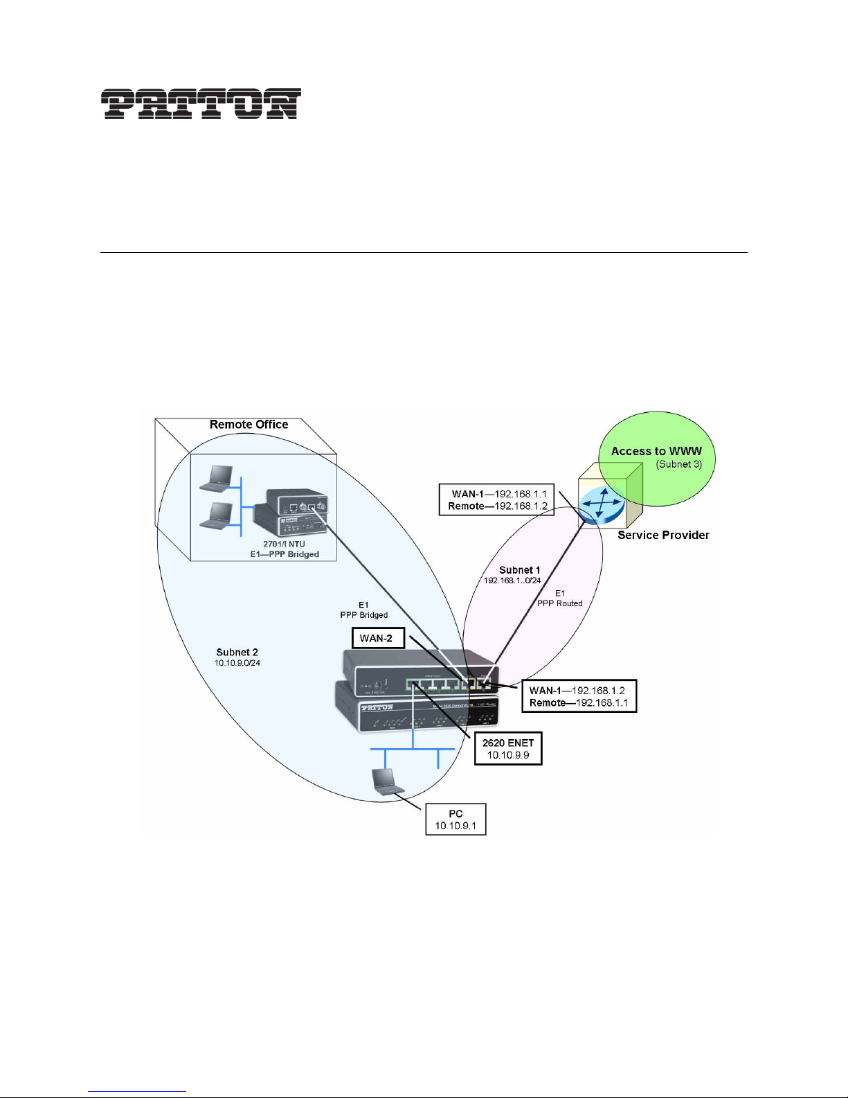
This application note describes how to configure your IPLink router to use both WAN ports in a dual-routed
application. WAN port 1 connects to your upstream network, which may be the ISP, and is the default gateway
for your private network. This is “Subnet 1” in figure 1. WAN port 2 can be connected to either a remote office
or to a DMZ which is on the same subnet (Subnet 2 in figure 1) as the Ethernet port. NAT can be enabled
between the two subnets. This lets you use private IP addresses ensuring the internal network structure is invisible to users on the Internet. The issue of security with comprehensive NAT configuration is outside the scope
of this application note, but will be addressed in another..
Figure 1. Dual-routed applicaiton with remote office on same subnet of Ethernet port
IP Addressing.
The IP address and subnet mask of the Ethernet port is 10.10.9.9/24.
WAN port 1 connects to the upstream router on the 192.168.1.0/24 subnet. WAN port 1 may obtain its IP
address via DHCP from the ISP or it may be configured with a fixed IP address if the appropriate arrangement
is made with the ISP.
Application Note: Configuring the IPLink™ Router for Dual Routed Application 1
Page 2

WAN port 2 and the Ethernet port are on the 10.10.9.0/24 subnet, so traffic is bridged betwween the two
interface ports. However IP traffic is routed between Subnet 1 and Subnet 2.
NAT configuration sets WAN port 1 as the “external” environment. WAN port 2 and the Ethernet port are
“internal” and the firewall would be configured to protect users in the main and remote offices.
PPP or Frame Relay.
Either PPP or Frame Relay communication links may be used. In this example, WAN port 1 is configured as a
routed PPP connection. WAN port 2 is bridged PPP because the users in the main office (on the IPLink’s
Ethernet) and the users in the remote office are on the same subnet, hence a bridged connection is the correct
selection.
Detailed Information
You will need the following information to correctly define the configurable parameters for this IPLink application.
Upstream Router Details
The upstream router provides access to the Internet and has the following characteristics.
• Channelized E1 (G.703/G.704)
- HDB3 line coding
- 120 Ohm twisted pair connection
- As master clock, the upstream router provides the clock to the 2620 WAN port 1.
- Time Slots: 1 - 31
• WAN Service
- Routed PPP
- Assumes that the 2620 is configured with a fixed IP address assigned by the ISP
- Router IP address & subnet mask: 192.168.1.1/24
2620/KK WAN Port 1 configuration parameters
These are the configurable parameters for WAN port 1 on the 2620/KK IPLink.
• Channelized E1 (G.703/G.704)
- HDB3 line coding
- 120 Ohm twisted pair connection
- Clocking mode-derived from the E1 (Receive Clock)
- Time Slots: 1-31
• WAN Service
- Routed PPP
- Interface 1 (WAN Port 1)
- Local WAN IP address and subnet mask: 192.168.1.2/24
Application Note: Configuring the IPLink™ Router for Dual Routed Application 2
Page 3

- Remote IP address and subnet mask (of the upstream router): 192.168.1.1/24
- No authentication
2620/KK Ethernet port parameters
The Ethernet port defines the IP subnet for WAN port 2.
• IP parameters
- IP address: 10.10.9.9
- Netmask: 255.255.255.0
- IP subnet: 10.10.9.0/24
- Gateway route: 192.168.1.2
2620/KK WAN Port 2 configurable parameters
The second WAN port is configured as follows:
• Channelized E1 (G.703/G.704)
- HDB3 line coding
- 120 Ohm twisted line pair connection
- Clocking: Not a configurable parameter. WAN port 2 derives clock from WAN 1 to synchronize the
transmitted signal on WAN port 2.
- Time Slots: 1-31
• WAN Service parameters
- Bridged PPP
- Interface 2: WAN port 2
- No authentication
Initial Configuration
Install and configure your IPLink WAN Access Router according to the directions in the 2603 & 2620 IPLink
Quick Start Guide, shipped with your router (and available online at www.patton.com/manuals). When cor-
rectly installed:
• The Ethernet port will connect to the same Ethernet LAN as your PC
• You can access the web management pages for configuration on the 2620/KK.
Access the IPLink Web Management Home Page
Access the IPlink Web Management Home page (see figure 2 on page 5) by using a web browser on your PC.
Enter the IPLink’s IP address and log in to the IPLink.
The IPLink home page is divided into two panes, a configuration menu pane on the left, and a configuration
information pane on the right. You will use the configuration menu pane to navigate from page to page. You
will use the configuration information pane to view and modify configurable parameters, and to view IPLink
system status information.
Application Note: Configuring the IPLink™ Router for Dual Routed Application 3
Page 4
1.
2.
3.
If unable to access the web management pages
Check these items if you are unable to access the 2620/KK’s management pages.
Verify that your PC and the 2620/KK are on the same subnet
Can you ping the 2620/KK from the PC? Can you ping the PC from the 2620/KK?
Check to see whether the Link/Act LED on the 2620/KK is lit. If not, the 2620/KK does not see an Ethernet signal from your PC.
WAN Ports 1 and 2 - Clocking configuration
The most critical issue to understand about the two WAN ports on the 2620/KK is the clocking mode. Notice
that WAN port 2 does not have any clocking mode parameters, because WAN port 2 uses the clocking of
WAN port 1 for its clocking source.
WAN port 1 on the other hand can derive its clocking source from either the 2620/KK’s internal clock or from
the received T1/E1 signal. In this example, we are assuming that WAN Port 1 is connecting to a service provider. Consequently we want to use its clock as the synchronizing source. In other words, configure Clocking
Mode to receive .
The second point to notice is that the two WAN ports can be configured independently for different line rates
(n x 64 kbps). In our example, we are configuring both for the same line rate of 31 DS0 time slots because we
don’t want one of them to become a bottleneck.
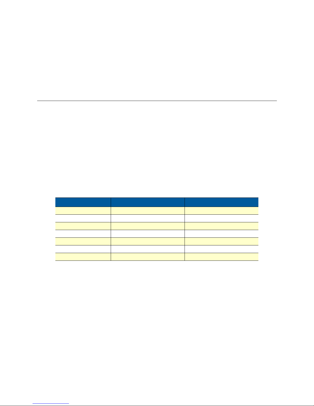
Table contains the configurable parameters and their values for both WAN ports.
Table 1. Configurable parameters - WAN Ports 1 & 2
Parameter
Time Slot Select 1-31 Payload Rate: 1984 kbps 1-3 Payload Rate: 1984 kbps
Line Options Channelized E1 (G.703/G.704) Channelized E1 (G.703/g.704)
Code Sel HDB3 HDB3
Line Build Out 120 Ohm 120 Ohm
Clocking Mode Receive Clock n/a
Idles Codes Enabled Enabled
Power Down Normal Normal
WAN Port 1 value
WAN Port 2 value
WAN Port 1 configuration
Following the hyperlink path to access WAN port 1’s E1 configuration web page. Menu --> WAN Port1 -->
Configuration. Using the values from table 1 for WAN Port 1, configure the E1 port as in figure 2. Click the
Create button to enable all the new parameter values.
Application Note: Configuring the IPLink™ Router for Dual Routed Application 4
Page 5

Figure 2. Configuration of WAN Port 1
Click on the Status hyerlink in the 2620 Configuration Menu to view any alarms. If it appears as figure 3, the
most proabable cause is no E1 connection to WAN Port 1.
Figure 3. Status of WAN Port 1 configured but not connected
Connect a valid E1 line to WAN Port 1 on the rear of the 2620/KK, and refresh the Status web page. If the
configuration matches the E1 parameters from the service provider, the alarms will cease, as in figure 4.
Figure 4. Connected E1 ro WAN Port 1
WAN Port 2 configuration
Following the hyperlink path to access WAN port 2’s E1 configuration web page. Menu --> WAN Port2 -->
Configuration. Using the values from table 1 for WAN Port 2, configure the E1 port as in figure 5. Click the
Create button to enable all the new parameter values.
Application Note: Configuring the IPLink™ Router for Dual Routed Application 5
Page 6

Figure 5. Configuration of WAN Port 2
You can view the Status web page for WAN Port 2 as you did earlier for WAN Port 1.
Now that the Physical Layer (1) has been configured, we will move to the Datalink Layer (2).
Configure the Routed PPP WAN Service for WAN Port 1
Consult the application diagram, figure 1, again. The next step is to establish a functional routed PPP link
between WAN Port 1 and the upstream route which is shown as the service provider. To look at the details of
the configuration for a better understanding, see figure 6. Notice that this routed PPP WAN service is in a different subnet than either the Ethernet or other WAN port and is called subnet 1 in figure 1.The subnet on
WAN port 1 is 192.168.1.0/24. You need the IP address of the service provider’s upstream router to configure
for the WAN gateway IP address. In this example, the upstream router’s IP address is 192.168.1.1/24.
Figure 6. WAN Port 1 - Routed PPP details
Go to the configuration web page for creating a routed PPP connection by following this hyperlink path on the
2620/KK IPLink’s web pages.
2620 Configuration Menu -> Services Configuration -> WAN -> Create a new service... -> PPP routed and
click on the Continue button. You should see a configuration page as in figure 7. Enter the values in the various fields and click on the Create button.
Description: wan1-ppp-rtd (you can choose your own description)
Interface: 1
WAN IP address: 0.0.0.0 255.255.255.255
Physical Port: wan1 (
Application Note: Configuring the IPLink™ Router for Dual Routed Application 6
Page 7

LLC header mode: off
HDLC header mode: on
No authentication (and leave the User name and Password fields blank).
It should look identical to the web page in figure 7.
Figure 7. WAN Port 1 PPP Routed configuration
From the “WAN connections” web page, click on the Edit... for this WAN service. You now see the “Edit Network Connection” webpage with numerous hyperlinks. Click on Edit ‘Ip Interface’”, enter these values and click
on the Create button.
Ipaddr: 192.168.1.2
Mask: 255.255.255.255
Dhcp: false (disabled)
MTU: 1500
Name: ppp-0 (already assigned to the WAN service upon creation)
Enabled: true
The web page should appear as figure 8.
Application Note: Configuring the IPLink™ Router for Dual Routed Application 7
Page 8

Figure 8. Assigning the IP address to WAN Port 1 on PPP Routed link
The last configuration item for the routed PPP routed link is the WAN IP address, which is the remote IP
address of the upstream router. Click on “Edit ‘PPP’”, then click on “View advanced attributes...” and enter the
IP addresses in the “Remote Ip:” and “Local Ip:” fields as in figure 9. Click on the Create button.
Figure 9. Configuring IP addresses for local and remote ends of routed PPP link
Assuming that you have connected the WAN Port 1 to the E1 line, the routed PPP session should come up.
When it is “UP” and also ready for data transfer, the web page appears as in figure 10. To reach it, click on the
“Edit ’PPP’” link, scroll down to see the Summary and Connect state fields. Notice that the Summary indi-
cates “Open for IP”. Not only is the PPP link officially “UP,” but it has also negotiated the Network Control
Protocol (NCP) which is necessary for data transfer. The Connect State is “connected.”
Figure 10. Routed PPP link up and transferring data
Application Note: Configuring the IPLink™ Router for Dual Routed Application 8
Page 9

All that remains is to create a route for the routing table, and the routed PPP WAN service should be fully
operational--at least from this end of the link.
Configuring the Routing Table
Under the “Services Configuration” menu item, click on “IP routes.” In the main window, click on the “Create
new Ip V4Route...” for adding routes in general. At this point in the configuration, we are setting the default
route. As in typical default routes, the destination is 0.0.0.0 with a netmask of 0.0.0.0, since it is the last resort
route--if no other routes define the port for routing an IP packet, send it to the port indicated by the default
route. In our example, the default routed port is the IP address of WAN port 1, 192.168.2. The interface is
ppp-0. See figure 11 for the correct configuration of the default route.
Figure 11. Adding Gateway address to routing table
Click on the IP routes hyperlink in the Configuration Menu. If the route is properly entered, a green check
mark is under the Valid column. See figure 12 as an example.
.
Figure 12. Indication of a valid route
Configure WAN Port 2 for Bridged PPP WAN Service
Configuring the bridged PPP WAN service for the second T1/E1 port is much simpler than the preceding
routed PPP configuration. Click on Create a new service... link on the WAN Connections page to select “PPP
Bridged.” figure 13 shows the values for each configurable parameter. Creating a Description is necessary for
the IPLink to build a WAN service. The most critical parameters are the Interface and Physical Port fields,
which are “2” and “wan2”, respectively. Click the Create button after entering all the values as in figure 13.
Application Note: Configuring the IPLink™ Router for Dual Routed Application 9
Page 10

1.
2.
Figure 13. WAN Port 2 - Configuring the bridged PPP link
After completing this configuration, click on the “Edit ’PPP’” link to see if the link status. A proper configuration and E1 link to WAN Port 2 should yield a valid bridged PPP link. In figure 14 the Summary states “open
for MAC” followed by the number of sent and received octets. Due to being a bridged PPP link, the link is not
“open for IP”, but “open for MAC”, the unit of encapsulation for bridges. The link has fully connected.
Test the connection
The first tests of the PPP connections are for successful pings to the IP address of WAN Port 1’s IP address.
Since the bridged PPP connection does not have a uniquely assigned IP address, the test is to ping the IP
address on the remote end of the bridged PPP connection.
If the ping fails, the first check is with the physical layer. If the physical layer is not operating correctly,
there is no hope of layer two protocols (PPP) to function.
– Verify that the E1 links are operating properly with no alarms or errors. If there are alarms or errors, they
must be resolved before any success can be expected for the PPP links.
Application Note: Configuring the IPLink™ Router for Dual Routed Application 10
Figure 14. Bridged PPP link up and running
Page 11

3.
4.
5.
– For the physical links to be free of alarms and errors, the minimum parameters must match those of the
provider’s E1 configuration-number of time slots, clear channel or structured E1, line coding, termination impedance which is 75 Ohms for coaxial and 120 Ohms for twisted pair physical media.
Once the physical layer is up, the next checks apply to the Datalink layer, layer 2. Look at the Summary
and Connect State information on the I Edit ’PPP’ page.
– If it is not connected, determine whether the link is in the process of connecting or dead. If dead, the
remote end may be causing a problem. If it is trying to connect without success, it may be a synchronization problem which may be caused by an error in the clocking mode of the E1 configuration. Rarely
should you need to change the other parameters. In fact, it is best not to change parameters like LCP
Max Configure, LCP Max Failure, and LCP Max Terminate. Any changes to these parameters can cause
erratic and unreliable connections.
If the PPP link is UP and connected, you may not be able to transfer data from an ill-configured routing
table. Be aware of the ping’s response to the attempted ping. The messages “Request timed out” and “host
destination not available” indicate different routing problems. Hence the importance to understand their
meaning and where in the routed path, the ping is failing.
You can also issue a ping or traceroute command from the IPLink. Under the System Configuration menu,
click on the Tools link for issuing Pings and Traceroute commands from the IPLink.
Date Created
March 1, 2006
Last Updated
March 31, 2006 3:51 pm
7622 Rickenbacker Drive
Gaithersburg, MD 20879
Tel: +1 301.975.1000
Fax: +1 301.869.9293
Application Note: Configuring the IPLink™ Router for Dual Routed Application 11
Page 12

Worksheet for implementing this application
This is a compilation of the key parameters for designing this application. Fill in the values and the configuration is simplified and, more importantly, less likely to have an error. Refer to figure 1, particularly to identify
the referrenced subnet, that is, 1, 2, or 3.
Table 2. Dual Routed Application Worksheet
Upstream Router
WAN Port 1
Channelized E1
Line Coding n/a
Impedance-120 or 75
Ohms
Clocking
Time Slots n/a
WAN Service (Subnet 3) (Subnet 1) (Subnet 2) (Subnet 2)
PPP-Routed or Bridged n/a
Interface n/a
Local IP address
Subnet mask
Remote IP address n/a
Subnet mask n/a
Authentication n/a
Gateway n/a
Master Receive Not config-
1 2
Of the
upstream
router
Of the
upstream
router
2620/KK
WAN Port 2 Ethernet
n/a
n/a
urable
n/a
n/a
n/a
IP
address/mask
of WAN port 1
Application Note: Configuring the IPLink™ Router for Dual Routed Application 12
 Loading...