

Page 1
For Quick
Start Installation
see page 27
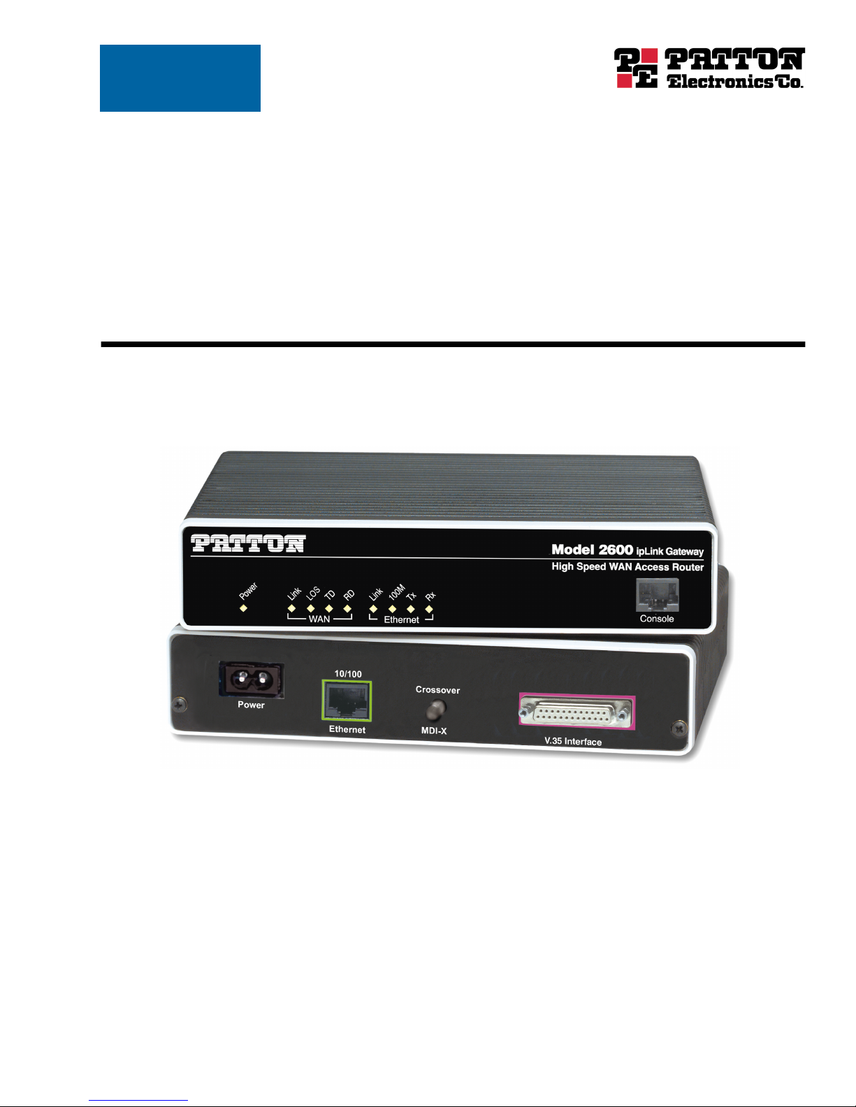
Models 2603, 2621, and 2635
IPLink Series High Speed Routers
User Guide
Sales Office: +1 (301) 975-1000
Technical Support: +1 (301) 975-1007
E-mail: support@patton.com
WWW: www.patton.com
Document Number: 033261U Rev. A
Part Number: 07M2603
Revised: July 14, 2003
Page 2

Patton Electronics Company, Inc.
7622 Rickenbacker Drive
Gaithersburg, MD 20879 USA
tel: +1 (301) 975-1000
fax: +1 (301) 869-9293
support: +1 (301) 975-1007
web: www.patton.com
e-mail: support@patton.com
Copyright © 2003, Patton Electronics Company. All rights reserved.
The information in this document is subject to change without notice. Patton Elec-
tronics assumes no liability for errors that may appear in this document.
Warranty Information
The software described in this document is furnished under a license and may be used
or copied only in accordance with the terms of such license.
Patton Electronics warrants all IPLink Series router components to be free from
defects, and will—at our option—repair or replace the product should it fail within
one year from the first date of the shipment.
This warranty is limited to defects in workmanship or materials, and does not cover
customer damage, abuse or unauthorized modification. If the product fails to perform
as warranted, your sole recourse shall be repair or replacement as described above.
Under no condition shall Patton Electronics be liable for any damages incurred by
the use of this product. These damages include, but are not limited to, the following:
lost profits, lost savings and incidental or consequential damages arising from the use
of or inability to use this product. Patton Electronics specifically disclaims all other
warranties, expressed or implied, and the installation or use of this product shall be
deemed an acceptance of these terms by the user.
Page 3

Contents
Contents ......................................................................................................................................................... 3
Compliance Information ................................................................................................................................ 9
Radio and TV Interference ...............................................................................................................................9
CE Notice .........................................................................................................................................................9
FCC Part 68 (ACTA) Statement (Model 2603 only) ........................................................................................9
Industry Canada Notice ....................................................................................................................................9
Service ............................................................................................................................................................10
About this guide ........................................................................................................................................... 11
Audience............................................................................................................................................................... 11
Structure............................................................................................................................................................... 11
Precautions ........................................................................................................................................................... 12
Factory default parameters.................................................................................................................................... 12
Typographical conventions used in this document................................................................................................ 13
General conventions .......................................................................................................................................13
Mouse conventions .........................................................................................................................................13
1 General Information...................................................................................................................................... 15
IPLink Series High Speed Routers overview ..........................................................................................................16
General attributes ............................................................................................................................................16
Ethernet ..........................................................................................................................................................17
Protocol support .............................................................................................................................................17
PPP Support ...................................................................................................................................................17
WAN Interfaces ..............................................................................................................................................17
Protocol Support .............................................................................................................................................17
Management ...................................................................................................................................................18
Security ...........................................................................................................................................................18
Front Panel Status LEDs and Console Port .....................................................................................................19
Console port .............................................................................................................................................20
Rear panel connectors and switches .................................................................................................................20
Power connector .......................................................................................................................................20
AC universal power supply ..................................................................................................................20
48 VDC power supply ........................................................................................................................21
Ethernet port (outlined in green) ...............................................................................................................21
MDI-X ......................................................................................................................................................21
Line port (outlined in yellow) ....................................................................................................................21
2 Product Overview.......................................................................................................................................... 23
Introduction..........................................................................................................................................................24
Applications Overview...........................................................................................................................................25
3 Quick Start Installation................................................................................................................................. 27
Hardware installation ............................................................................................................................................28
3
Page 4

Contents
Models 2603, 2621, & 2635 High Speed Routers User Guide
What you will need .........................................................................................................................................28
Interface cable installation ...............................................................................................................................28
Installing an interface cable on the IPLink 2603’s T1/E1 interface port ....................................................29
Installing an interface cable on the IPLink 2621’s X.21 interface port .......................................................31
Installing an interface cable on the IPLink 2635’s V.35 interface port .......................................................33
Installing the AC power cord ..........................................................................................................................34
Installing the Ethernet cable ............................................................................................................................36
IP address Quick Start modification ................................................................................................................36
Web Operation and Configuration .................................................................................................................37
PC Configuration .....................................................................................................................................37
Web Browser .............................................................................................................................................37
4 Configuring the IPLink Router..................................................................................................................... 41
WAN Port Configuration......................................................................................................................................42
Serial Interface ................................................................................................................................................42
Variables ...................................................................................................................................................42
Web Interface Configuration ....................................................................................................................43
CLI Configuration ....................................................................................................................................43
T1/E1 Interface Configuration .......................................................................................................................44
Configuring the IPLink Series 2603 for T1 Operation ..............................................................................44
Web Configuration .............................................................................................................................44
CLI configuration ...............................................................................................................................45
Configuring the IPLink Series 2603 for E1 Operation ..............................................................................46
Web Configuration .............................................................................................................................46
CLI configuration ...............................................................................................................................47
WAN Service Configuration..................................................................................................................................47
PPP Configuration ..........................................................................................................................................48
PPPoH Configuration ...............................................................................................................................48
PPPoH Bridged Remote Site Configuration .......................................................................................48
Central Site Configuration ..................................................................................................................49
PPPoh Routed ...........................................................................................................................................50
Remote site configuration ...................................................................................................................50
Central Site Configuration ..................................................................................................................52
Frame Relay Configuration .............................................................................................................................53
Frame Relay bridged .................................................................................................................................53
Remote Site Configuration .................................................................................................................54
Central site configuration ...................................................................................................................56
Frame Relay Routed ..................................................................................................................................59
Remote Site Configuration .................................................................................................................59
Central site configuration ...................................................................................................................63
LMI Configuration .........................................................................................................................................64
Frame Relay Local Management Interface .................................................................................................64
LMI Configuration Options .....................................................................................................................65
CLI Configuration Methods .....................................................................................................................65
4
Page 5

5
Models 2603, 2621, & 2635 High Speed Routers User Guide
Contents
Web Configuration Methods ....................................................................................................................66
5 Security ......................................................................................................................................................... 69
Introduction..........................................................................................................................................................70
Configuring the router ..........................................................................................................................................70
Configuring the security interfaces.........................................................................................................................71
Deleting a Firewall Policy ...............................................................................................................................72
Enabling the Firewall.............................................................................................................................................73
Firewall Portfilters .................................................................................................................................................73
Security Triggers....................................................................................................................................................74
Intrusion Detection System (IDS) .........................................................................................................................76
6 NAT (Network Address Translation) ............................................................................................................ 79
Introduction..........................................................................................................................................................80
Enabling NAT ................................................................................................................................................80
Global address pool and reserved map .............................................................................................................81
7 SNMP Daemon Settings................................................................................................................................ 83
SNMP Daemon Settings window..........................................................................................................................84
Static Variables ...............................................................................................................................................84
Community Table ..........................................................................................................................................85
Save SNMP Configuration .............................................................................................................................85
Misc. System Settings window...............................................................................................................................86
CPU Usage .....................................................................................................................................................86
Enabled Status of System Services ...................................................................................................................87
MAC Filtering of the Bridge Interface...................................................................................................................87
8 Monitoring Status ......................................................................................................................................... 89
Status LEDs...........................................................................................................................................................90
9 T1/E1 Diagnostics......................................................................................................................................... 91
Introduction..........................................................................................................................................................92
Ping.......................................................................................................................................................................92
Traceroute.............................................................................................................................................................92
2603 IPLink’s Line Loop.......................................................................................................................................92
D4 Loop (CO loop) ..............................................................................................................................................93
Operating Remote Digital Loopback (RDL) .........................................................................................................94
BIT Error Rate (V.52) Diagnostics........................................................................................................................95
T1/E1 connection Status ................................................................................................................................95
Alarms ............................................................................................................................................................96
Transceiver Status ...........................................................................................................................................96
FDL statistics (T1 only) ..................................................................................................................................96
E1/T1 DS0 Monitor .......................................................................................................................................96
Software Upgrades.................................................................................................................................................96
Configuration .................................................................................................................................................97
10 Contacting Patton for assistance ................................................................................................................... 99
Introduction........................................................................................................................................................100
Page 6

Contents
Models 2603, 2621, & 2635 High Speed Routers User Guide
Contact information............................................................................................................................................100
Warranty Service and Returned Merchandise Authorizations (RMAs).................................................................100
Warranty coverage ........................................................................................................................................100
Out-of-warranty service ...........................................................................................................................100
Returns for credit ....................................................................................................................................100
Return for credit policy ...........................................................................................................................101
RMA numbers ..............................................................................................................................................101
Shipping instructions ..............................................................................................................................101
A Specifications .............................................................................................................................................. 103
General Characteristics ........................................................................................................................................104
Ethernet ..............................................................................................................................................................104
Sync Serial Interface ............................................................................................................................................104
T1/E1 Interface...................................................................................................................................................104
Protocol Support .................................................................................................................................................105
PPP Support........................................................................................................................................................105
Management .......................................................................................................................................................105
Security ...............................................................................................................................................................106
Compliance Standard Requirements....................................................................................................................106
Australia Specific .....................................................................................................................................106
Dimensions .........................................................................................................................................................106
Power and Power Supply Specifications...............................................................................................................106
AC universal power supply ......................................................................................................................106
48 VDC power supply ............................................................................................................................107
B Cable Recommendations ............................................................................................................................ 109
Ethernet Cable ....................................................................................................................................................110
Adapter................................................................................................................................................................110
C Physical Connectors ................................................................................................................................... 111
RJ-45 shielded 10/100 Ethernet port...................................................................................................................112
RJ-45 non-shielded RS-232 console port (EIA-561)............................................................................................112
Serial port............................................................................................................................................................113
V.35 (DB-25 Female Connector) ..................................................................................................................113
X.21 (DB-15 Connector) ..............................................................................................................................113
E1/T1 (RJ-48C Connector) ..........................................................................................................................114
D Command Line Interface (CLI) Operation ................................................................................................ 115
Introduction........................................................................................................................................................116
CLI Terminology ................................................................................................................................................116
Local (VT-100 emulation) ............................................................................................................................116
Remote (Telnet) ............................................................................................................................................116
Using the Console .........................................................................................................................................116
Administering user accounts................................................................................................................................118
Adding new users ..........................................................................................................................................118
Setting user passwords ...................................................................................................................................118
6
Page 7

7
Models 2603, 2621, & 2635 High Speed Routers User Guide
Changing user settings ..................................................................................................................................119
Controlling login access ...........................................................................................................................119
Controlling user access ............................................................................................................................119
Contents
Page 8

Contents
Models 2603, 2621, & 2635 High Speed Routers User Guide
8
Page 9

Compliance Information
and TV
Radio
The IPLink Series router generates and uses radio frequency energy, and if not installed and used properly-that
is, in strict accordance with the manufacturer’s instructions-may cause interference to radio and television
reception. The IPLink router have been tested and found to comply with the limits for a Class A computing
device in accordance with specifications in Subpart B of Part 15 of FCC rules, which are designed to provide
reasonable protection from such interference in a commercial installation. However, there is no guarantee that
interference will not occur in a particular installation. If The IPLink Series router does cause interference to
radio or television reception, which can be determined by disconnecting the unit, the user is encouraged to try
to correct the interference by one or more of the following measures: moving the computing equipment away
from the receiver, re-orienting the receiving antenna and/or plugging the receiving equipment into a different
AC outlet (such that the computing equipment and receiver are on different branches).
Interference
CE Notice
The CE symbol on your Patton Electronics equipment indicates that it is in compliance with the Electromagnetic Compatibility (EMC) directive and the Low Voltage Directive (LVD) of the European Union (EU). A
Certificate of Compliance is available by contacting Technical Support.
FCC Part 68 (ACTA) Statement (Model 2603 only)
This equipment complies with Part 68 of FCC rules and the requirements adopted by ACTA. On the bottom
side of this equipment is a label that contains—among other information—a product identifier in the format
US: AAAEQ##TXXXX . If requested, this number must be provided to the telephone company.
A plug and jack used to connect this equipment to the premises wiring and telephone network must comply
with the applicable FCC Part 68 rules and requirements adopted by the ACTA.
This equipment uses a Universal Service Order Code (USOC) jack: RJ-11C.
If this equipment causes harm to the telephone network, the telephone company will notify you in advance
that temporary discontinuance of service may be required. But if advance notice isn’t practical, the telephone
company will notify the customer as soon as possible. Also, you will be advised of your right to file a complaint
with the FCC if you believe it is necessary.
The telephone company may make changes in its facilities, equipment, operations or procedures that could
affect the operation of the equipment. If this happens the telephone company will provide advance notice in
order for you to make necessary modifications to maintain uninterrupted service.
If trouble is experienced with this equipment, for repair or warranty information, please contact our company.
If the equipment is causing harm to the telephone network, the telephone company may request that you disconnect the equipment until the problem is resolved.
Connection to party line service is subject to state tariffs. Contact the state public utility commission, public
service commission or corporation commission for information.
Industry Canada Notice
Note
This equipment meets the applicable Industry Canada Terminal
Equipment Technical Specifications. This is confirmed by the regis-
9
Page 10

Compliance Information
Models 2603, 2621, & 2635 High Speed Routers User Guide
tration number. The abbreviation, IC , before the registration number
signifies that registration was performed based on a Declaration of
conformity indicating that Industry Canada technical specifications
were met. It does not imply that Industry Canada approved the
equipment.
Service
All warranty and non-warranty repairs must be returned freight prepaid and insured to Patton Electronics. All
returns must have a Return Materials Authorization number on the outside of the shipping container. This
number may be obtained from Patton Electronics Technical Services at:
• Tel: +1 (301) 975-1007
• Email: support@patton.com
• URL: www.patton.com
Note
Packages received without an RMA number will not be accepted.
10
Page 11

About this guide
This guide describes installing and configuring Patton Electronics IPLink Series High Speed Routers. The
instructions in this guide are based on the following assumptions:
• The router may connect to a serial DTE device or T1/E1 line
• There is a LAN connected to the Ethernet port of the router
Audience
This guide is intended for the following users:
• Operators
• Installers
• Maintenance technicians
Structure
This guide contains the following chapters and appendices:
• Chapter 1 provides information about router features and capabilities
• Chapter 2 contains an overview describing router operation
• Chapter 3 provides quick start installation procedures
• Chapter 4 describes configuring the IPLink router
• Chapter 5 describes configuring security for the router
• Chapter 6 describes configuring for network address translation (NAT)
• Chapter 7 describes configuring SNMP daemon settings
• Chapter 8 contains definitions for the LED status indicators
• Chapter 9 describes router diagnostics
• Appendix A contains specifications for the routers
• Appendix B provides cable recommendations
• Appendix C describes the router’s ports
• Appendix D describes how to use the command line interface (CLI)
For best results, read the contents of this guide before you install the router.
11
Page 12
About this guide
Models 2603, 2621, & 2635 High Speed Routers User Guide
Precautions
Notes and cautions, which have the following meanings, are used throughout this guide to help you become
aware of potential Router problems. Warnings relate to personal injury issues, and Cautions refer to potential
property damage.
Note
Calls attention to important information.
The shock hazard symbol and WARNING heading indicate a potential electric
shock hazard. Strictly follow the warning instructions to avoid injury caused
by electric shock.
The alert symbol and WARNING heading indicate a potential safety hazard.
Strictly follow the warning instructions to avoid personal injury.
The shock hazard symbol and CAUTION heading indicate a
potential electric shock hazard. Strictly follow the instructions to
avoid property damage caused by electric shock.
The alert symbol and CAUTION heading indicate a potential hazard. Strictly follow the instructions to avoid property damage.
Factory default parameters
IPLink Series High Speed Routers have the following factory default parameters.
• Ethernet IP address: 192.168.200.10/24
• WAN Connection: PPPoH Bridged
• Ethernet and serial connections
• MDI (LAN connector)
• Model 2621 (X.21)—DB-15 port (DTE)
• Model 2635 (V.35)—DB-25 port (DCE, DTE when using special V.35 cable)
• Model 2603/T—T1 configuration. RJ-48C (100-ohm) interface
• Model 2603/K—E1 configuration. RJ-48C (120-ohm) and dual-BNC interface (75-ohm)
12
Page 13

13
Models 2603, 2621, & 2635 High Speed Routers User Guide
Typographical conventions used in this document
This section describes the typographical conventions and terms used in this guide.
General conventions
The procedures described in this manual use the following text conventions:
Table 1. General conventions
Convention Meaning
Futura bold type
Italicized Futura type
Futura type
Garamond bold type
< >
Are you ready?
% dir *.*
Indicates the names of menu bar options.
Indicates the names of options on pull-down menus.
Indicates the names of fields or windows.
Indicates the names of command buttons that execute an action.
Angle brackets indicate function and keyboard keys, such as <SHIFT>,
<CTRL>, <C>, and so on.
All system messages and prompts appear in the Courier font as the
system would display them.
Bold Courier font indicates where the operator must type a response or
command
About this guide
Mouse conventions
The following conventions are used when describing mouse actions:
Table 2. Mouse conventions
Convention Meaning
Left mouse button
Right mouse button This button refers the secondary or rightmost mouse button (unless you have
Point This word means to move the mouse in such a way that the tip of the pointing
Click Means to quickly press and release the left or right mouse button (as instructed in
Double-click Means to press and release the same mouse button two times quickly
Drag This word means to point the arrow and then hold down the left or right mouse but-
This button refers to the primary or leftmost mouse button (unless you have
changed the default configuration).
changed the default configuration).
arrow on the screen ends up resting at the desired location.
the procedure). Make sure you do not move the mouse pointer while clicking a
mouse button.
ton (as instructed in the procedure) as you move the mouse to a new location.
When you have moved the mouse pointer to the desired location, you can release
the mouse button.
Page 14

About this guide
Models 2603, 2621, & 2635 High Speed Routers User Guide
14
Page 15

Chapter 1
General Information
Chapter contents
IPLink Series High Speed Routers overview ..........................................................................................................16
General attributes ............................................................................................................................................16
Ethernet ..........................................................................................................................................................17
Protocol support .............................................................................................................................................17
PPP Support ...................................................................................................................................................17
WAN Interfaces ..............................................................................................................................................17
Protocol Support .............................................................................................................................................17
Management ...................................................................................................................................................18
Security ...........................................................................................................................................................18
Front Panel Status LEDs and Console Port .....................................................................................................19
Console port .............................................................................................................................................20
Rear panel connectors and switches .................................................................................................................20
Power connector .......................................................................................................................................20
AC universal power supply .................................................................................................................. 20
48 VDC power supply ........................................................................................................................ 20
Ethernet port (outlined in green) ...............................................................................................................21
MDI-X ......................................................................................................................................................21
Line port (outlined in yellow) ....................................................................................................................21
15
Page 16

1 • General Information Models 2603, 2621, & 2635 High Speed Routers User Guide
IPLink Series High Speed Routers overview
The IPLink Series of gateway routers/bridges combine full set of high-speed IP routing features and WAN
access via PPP/IP/FR protocols. All IPLink routers come with an auto-sensing full-duplex 10/100Base-T
Ethernet port, cross-over switch, console port, and internal or external power supply. There are three versions
in the IPLink series corresponding to a choice of WAN interface:
• The Model 2603 is equipped with an integrated T1/E1 CSU/DSU for connection to full and fractional
T1/E1 services.
• The Model 2621 is equipped with DTE/DCE user configurable X.21 interface.
• The Model 2635 equipped with a V.35 interface presented on a female DB-25 connector.
The IPLink routers provide selectable bridging or routing functionality along with advanced IP features such as
NAT/NAPT, Firewall, and DHCP. A complete set of configurable PPP/IP/FR WAN protocols allow a wide
range of choices when connecting branches via common WAN services. The IPLink routers boast easy installation offering Console/VT-100, Telnet, and HTTP/SNMP management options.
The following sections describes the IPLink series features and capabilities:
• General attributes, see section “General attributes”
• Ethernet, see section “Ethernet” on page 17
• Protocol support, see section “Protocol support” on page 17
• PPP support, see section “PPP Support” on page 17
• Management, see section “Management” on page 18
• WAN interface, see section “WAN Interfaces” on page 17
• Security, see section “Security” on page 18
• Front panel status LED see section “Front Panel Status LEDs and Console Port” on page 19
General attributes
• Compact, low cost router/bridge
• 10/100 Ethernet
• Unlimited host support.
• Comprehensive hardware diagnostics, works with any operating system, easy maintenance and effortless
installation.
• Plug-and-Play operation for fast and seamless turn-up with pre-configured WAN and LAN options.
• Built-in web configuration.
• Setup allows for standard IP address and unique method for entering an IP address and mask without
requiring a console connection. Default IP address of 192.168.1.1/24.
• Simple software upgrades obtained via FTP and loaded into FLASH memory.
• Front panel LEDs indicate Power, WAN, and Ethernet LAN speed and status.
• Convenient and standard RJ connectors for Ethernet, Line, and Console.
16 IPLink Series High Speed Routers overview
Page 17

Models 2603, 2621, & 2635 High Speed Routers User Guide 1 • General Information
• Field factory default option.
• Standard one-year warranty.
Ethernet
• Auto-sensing full-duplex 10Base-T/100Base-TX Ethernet.
• Standard RJ-45 connector
• Built-in MDI-X cross-over switch.
• IEEE 802.1d transparent learning bridge up to 1,024 addresses and Spanning Tree.
• 8 IP address/subnets on Ethernet interface.
Protocol support
• Complete internetworking with IP (RFC 741), TCP (RFC 793), UDP (RFC 768), ICMP (RFC 950),
ARP (RFC 826).
• IP router with RIP (RFC 1058), RIPv2 (RFC 2453) for up to 64 static routes.
• Built-in ping and traceroute facilities.
• Integrated DHCP server (RFC 2131).
• DHCP relay agent (RFC 2132/RFC 1542) with 8 individual address pools.
• DNS relay with primary and secondary name server selection.
• NAT (RFC 3022) with network address port translation (NAPT), MultiNat with 1:1, Many:1,
Many:Many mapping, Port/IP redirection and mapping.
PPP Support
• Point-to-point protocol over HDLC
• PPPoE (RFC 2516) Client for autonomous network connection. Eliminates the requirement of installing
client software on a local PC and allows sharing of the connection across a LAN.
• User configurable PPP PAP (RFC 1661) or CHAP (RFC 1994) authentication.
WAN Interfaces
• T1/E1, V.35 or X.21 interfaces
• Available with female RJ-48C, dual BNC, DB-25, and DB-15 connectors
• User configurable DTE/DCE for X.21
Protocol Support
• Complete internetworking with IP (RFC 741), TCP (RFC 793), UDP (RFC 768), ICMP (RFC 950),
ARP (RFC 826).
• IP router with RIP (RFC 1058), RIPv2 (RFC 2453),
• Up to 64 static routes with user selectable priority over RIP/OSPF routes.
• Built-in ping facilities.
IPLink Series High Speed Routers overview 17
Page 18

1 • General Information Models 2603, 2621, & 2635 High Speed Routers User Guide
• Integrated DHCP server (RFC 2131). Selectable general IP leases and user specific MAC/IP parings. Select-
able lease period.
• DHCP relay agent (RFC 2132/RFC 1542) with 8 individual address pools.
• DNS relay with primary and secondary Name Server selection.
• NAT (RFC 3022) with network address port translation (NAPT) for cost-effective sharing of a single DSL
connection. Integrated application level gateway with support for over 80 applications.
• NAT MultiNat with 1:1 mapping.
• NAT Many:1.
• NAT Many:Many mapping.
• NAT Port/IP redirection and mapping.
• uPNP controlled device for seamless networked device interconnectivity and Windows XP integration.
• IGMPv2 Proxy support (RFC 2236).
• Frame Relay with Annex A/D/LMI, RFC 1490 MpoFR and FRF.12 Fragmentation.
Management
• User selectable HDLC or Frame Relay WAN datalink connection.
• Web-Based configuration via embedded web server
• CLI menu for configuration, management, and diagnostics.
• Local/Remote CLI (VT-100 or Telnet).
• SNMPv1 (RFC 1157) MIB II (RFC 1213)
• Quick Start Setup runs through common options to simplify circuit turn-up.
• Logging via SYSLOG, and VT-100 console. Console port set at 9600 bps 8/N/1 settings no flow control.
Security
• Packet filtering firewall for controlled access to and from LAN/WAN. Support for 255 rules in 32 filter sets.
16 individual connection profiles.
• DoS Detection/protection. Intrusion detection, Logging of session, blocking and intrusion events and Real-
Time alerts. Logging or SMTP on event.
• Password protected system management with a username/password for console and virtual terminal. Sepa-
rate user selectable passwords for SNMP RO/RW strings.
• Access list determining up to 5 hosts/networks which are allowed to access management system
SNMP/HTTP/TELNET.
• Logging or SMTP on events: POST, POST errors, PPP/DHCP, IP.
18 IPLink Series High Speed Routers overview
Page 19
Models 2603, 2621, & 2635 High Speed Routers User Guide 1 • General Information
Front Panel Status LEDs and Console Port
The IPLink routers have all status LEDs and console port on the front panel of the unit, and all other electrical
connections are located on the rear panel.
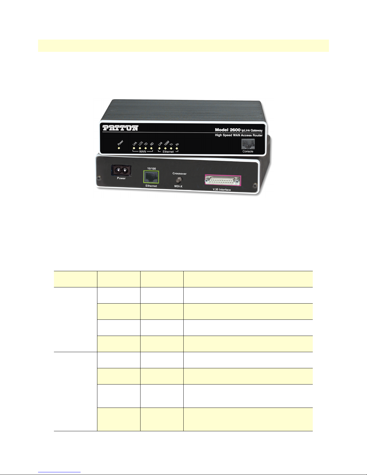
Figure 1. IPLink Series Router (Model 2635 shown)
The status LEDs from left to right are (see table 3 for LED descriptions):
• Power
• Sync Serial TD, RD, CTS, and DTR
• Ethernet Link, 100M, Tx, and Rx
Table 3. Status LED descriptions
Power Green ON indicates that power is applied. Off indi-
cates that no power is applied.
T1/E1 Link Green Solid green: connected
Off: disconnected
LOS Red On: indicates a T1/E1 loss-of-frame condition. It
also indicates that no T1/E1 signal is detected.
TD Green Green: indicates a binary ‘0’ condition
off
: indicates a binary ‘1’or idle condition
RD Green Green: indicates a binary ‘0’condition
off: indicates a binary ‘1’ or idle condition
Sync Serial TD Green Green: indicates a binary ‘0’ condition
off
: indicates a binary ‘1’or idle condition
RD Green Green: indicates a binary ‘0’condition
off: indicates a binary ‘1’ or idle condition
CTS Green ON: indicates the CTS signal from the router is
active, binary ‘1’
off: indicates CTS is binary ‘0’
DTR Green ON: indicates the DTR signal from the DTE
device attached to the serial port is active,
binary ‘1’
IPLink Series High Speed Routers overview 19
Page 20

1 • General Information Models 2603, 2621, & 2635 High Speed Routers User Guide
Table 3. Status LED descriptions (Continued)
Ethernet Link Green ON: indicates an active 10/100 Base-T connec-
tion
100M Green ON: connected to a 100BaseT LAN
Off: connected to a 10BaseT LAN
Tx Green Flashing: when transmitting data from the router
to the Ethernet
Rx Green Flashing: when transmitting data from the Ether-
net to the router.
Console port
Located on the front panel, the unshielded RJ-45 RS-232 console DCE port (EIA-561) with the pin-out listed
in the following table:
Pin No. Signal Direction Signal Name
1 Out DSR
2 Out CD
3 In DTR
4 — Signal Ground
5 Out RD
6 In TD
7 Out CTS
8 In RTS
Rear panel connectors and switches
On the rear panel from left to right are the following:
• Power input connector
• Ethernet connector
• MDI-X switch
• WAN port (V.35, X.21, T1/E1)
Power connector
AC universal power supply.
The IPLink Series router offers internal or external AC power supply options.
• The internal power supply connects to an AC source via an IEC-320 connector (100–240 VAC, 200 mA,
50/60 Hz)
• The external power supply connects to an external source providing +5 VDC via a barrel-type connector
20 IPLink Series High Speed Routers overview
Page 21
Models 2603, 2621, & 2635 High Speed Routers User Guide 1 • General Information
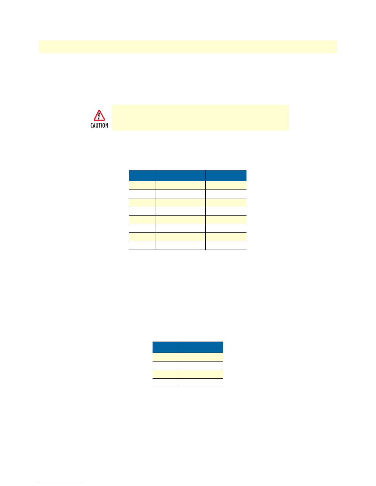
48 VDC power supply.
• The DC power supply connects to a DC source via a terminal block
• Rated voltage and current: 36–60 VDC, 400 mA
Connect the equipment to a 36–60 VDC source that is electrically isolated from the AC source. The 36–60 VDC source is to
be reliably connected to earth.
Ethernet port (outlined in green)
Shielded RJ-45 10Base-T/100Base-TX Ethernet port using pins 1,2,3, & 6. See MDI-X switch for hub or transceiver configuration.The following table defines conditions that occur when the MDI-X switch is in the out position.
Pin No. Signal Direction Signal Name
1 Output TX+
2 Output TX3 Input RX+
4 — —
5 — —
6 Input RX7 — —
8 — —
MDI-X
The MDI-X push switch operates as follows:
• When in the default “out” position, the Ethernet circuitry takes on a straight-through MDI configuration
and functions as a transceiver. It will connect directly to a hub.
• When in the “in” position, the Ethernet circuitry is configured in cross-over MDI-X mode so that a
straight-through cable can connect The IPLink Series router’s Ethernet port directly to a PC’s NIC card.
Line port (outlined in yellow)
The RJ-11/4 DSL line port uses pins 2 and 3 of the RJ-11 port.
Pin No. Signal Name
1 —
2 In/Out-A
3 In/Out-B
4 —
IPLink Series High Speed Routers overview 21
Page 22

1 • General Information Models 2603, 2621, & 2635 High Speed Routers User Guide
22 IPLink Series High Speed Routers overview
Page 23

Chapter 2 Product Overview
Chapter contents
Introduction..........................................................................................................................................................24
Applications Overview...........................................................................................................................................25
23
Page 24

2 • Product Overview Models 2603, 2621, & 2635 High Speed Routers User Guide
Introduction
The IPLink Series Router operates as a bridge or a router and has two ports for communication:
• The Ethernet port—Connects to the LAN side of the connection
• The Serial port—Connects to local DTE devices (Model 2621 and 2635)
• The T1/E1 port—Connects directly to T1/E1 lines (Model 2603)
the router provides all layer 2 and layer 3 protocols required for end-to-end-link communication.
When configuring the IPLink router, questions must be answered so the IPLink router functions as desired.
For example, when a router or bridge module needs to be activated, some questions would be:
• Is a default gateway required?
• Which encapsulation technique is best for this application: Frame Relay, PPP, or another?
These decisions can be made and implemented more easily if The IPLink Series router’s fundamental architecture
is understood. Also, while configuring The IPLink Series router via a browser using the built-in HTTP server is
very intuitive, an understanding of the architecture is essential when using the command-line interface (CLI)
commands.
The fundamental building blocks comprise a router or bridge, interfaces, and transports. the router and bridge
each have interfaces. A transport provides the path between an interface and an external connection. For example, the Ethernet transport attaches to an Internet Protocol (IP) interface. A transport consists of layer 2 and
everything below it. Creating a transport and attaching it to a bridge or router’s interface enables data to be
bridged or routed. The supported transports are PPPoE, Frame Relay, PPPoH, and Ethernet.
Configuring an interface and transport for the router or bridge requires naming the interface and transport before
attaching them. When using the built-in HTTP server web browser, this is done automatically. But when configuring The IPLink Series router via CLI commands through the RS-232 control port, it must be done manually.
24 Introduction
Page 25

Models 2603, 2621, & 2635 High Speed Routers User Guide 2 • Product Overview
Applications Overview
Patton’s IPLink Gateway routers deliver all the advanced features for secure, reliable, and high speed Internet
data connections. They combine ease-of-use with powerful data routing to make shared Internet connectivity
simple and easy.
With NAT support, the IPLink routers offer convenient and economical operation by using a single IP address
while the integrated DHCP server automates IP address assignment for connected LAN computers. Security is
standard with built-in firewall and violation alerting features that protect the network from would-be intruders.
Figure 2. Sync Serial Application
Figure 3. T1/E1 Application
Applications Overview 25
Page 26

2 • Product Overview Models 2603, 2621, & 2635 High Speed Routers User Guide
26 Applications Overview
Page 27

Chapter 3 Quick Start Installation
Chapter contents
Hardware installation ............................................................................................................................................28
What you will need .........................................................................................................................................28
Interface cable installation ...............................................................................................................................28
Installing an interface cable on the IPLink 2603’s T1/E1 interface port ....................................................29
Installing an interface cable on the IPLink 2621’s X.21 interface port .......................................................31
Installing an interface cable on the IPLink 2635’s V.35 interface port .......................................................33
Installing the AC power cord ..........................................................................................................................34
Installing the Ethernet cable ............................................................................................................................36
IP address Quick Start modification ................................................................................................................36
Web Operation and Configuration .................................................................................................................37
PC Configuration .....................................................................................................................................37
Web Browser .............................................................................................................................................37
27
Page 28

3 • Quick Start Installation Models 2603, 2621, & 2635 High Speed Routers User Guide
Hardware installation
If you are already familiar with IPLink Series Router installation and configuration, this chapter will enable
you to finish the job quickly. Installation consists of the following:
• Preparing for the installation (see section “What you will need”)
• Installing the T1/E1 WAN, X.21, or V.35 interface cable (see section “Interface cable installation”)
• Hooking up network cables, verifying that the unit will power up, and running a HyperTerminal session
(see section “Installing the Ethernet cable” on page 36)
• Changing the IP address from the factory default setting (see section “IP address Quick Start modification”
on page 36)
• Launching a web browser in preparation for configuring the modem (see “Web Operation and Configura-
tion” on page 37)
What you will need
• IPLink Series High Speed Router
• Ethernet cable with RJ45 plugs on each end (included with router)
• DB9-RJ45 adapter (included with router)
• RJ45/RJ45 straight-through cable for connecting to control port (included with router)
• PC computer with HyperTerminal or equivalent VT-100 emulation program, or an ASCII terminal (also
called a dumb terminal).
Interface cable installation
An IPLink Series router comes with a T1/E1 WAN, V.35, or X.21 interface. Refer to the appropriate section to
install an interface cable on your IPLink router:
• Model 2603 router (see “Installing an interface cable on the IPLink 2603’s T1/E1 interface port” on
page 29)
• Model 2621 router (see “Installing an interface cable on the IPLink 2621’s X.21 interface port” on page 31)
• Model 2635 router (see “Installing an interface cable on the IPLink 2635’s V.35 interface port” on page 33)
28 Hardware installation
Page 29
Models 2603, 2621, & 2635 High Speed Routers User Guide 3 • Quick Start Installation
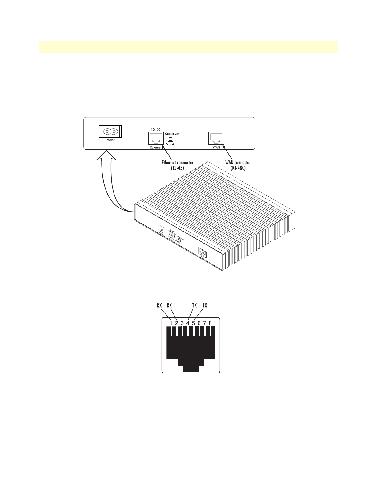
Installing an interface cable on the IPLink 2603’s T1/E1 interface port
The IPLink Models 2603/K and 2603/T come with a selectable T1/E1 WAN interface (see figure 4). Located
on the back of the IPLink, the T1 and E1 interfaces are presented on an RJ-48C connector with selectable line
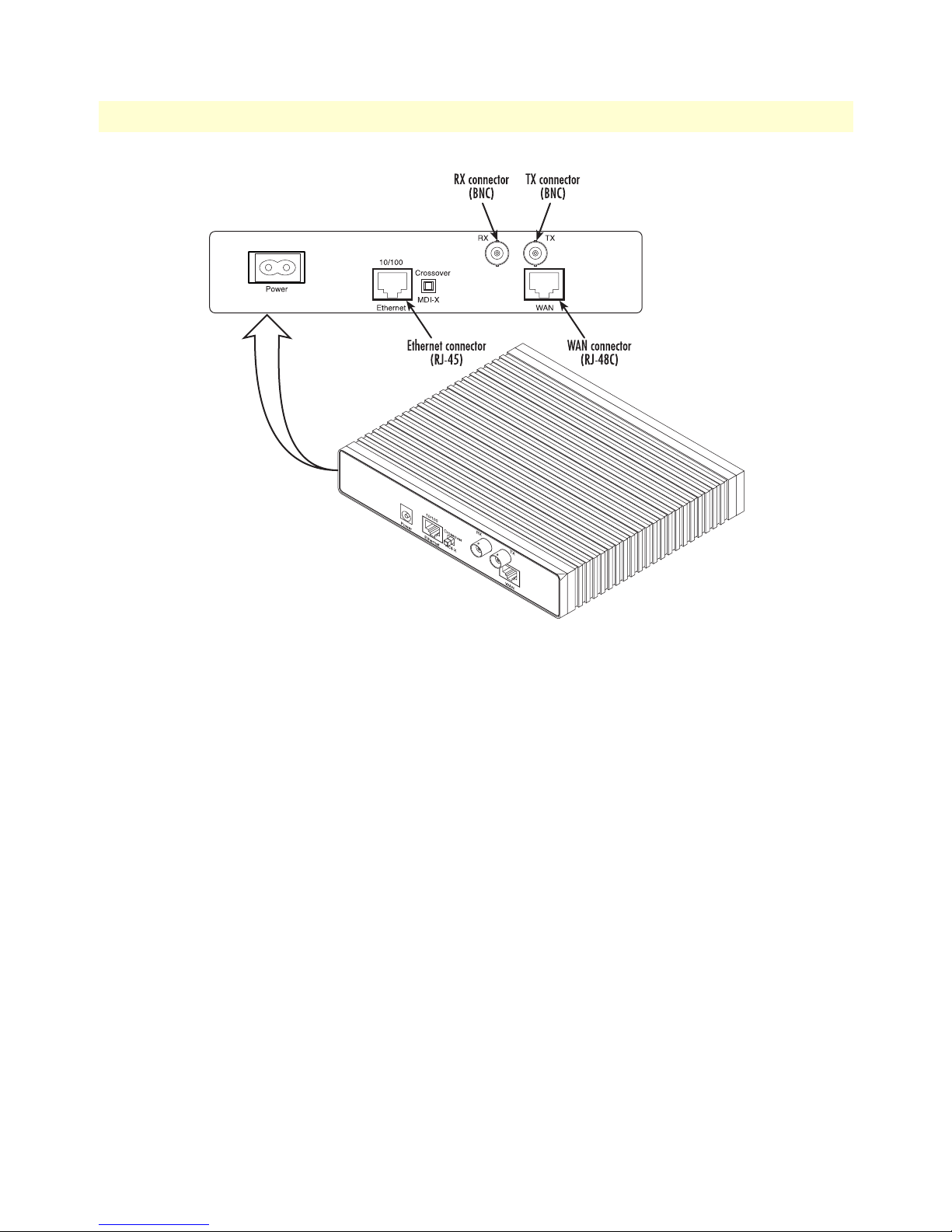
impedances of 100-ohms for T1 and 120-ohms for E1 lines (see figure 5). The 2603/K also comes with dual
BNC for alternate connection to unbalanced 75-ohm E1 lines (see figure 6 on page 30).
Figure 4. Rear View of the 2603/T showing location of Ethernet and WAN connectors
Figure 5. RJ-48C pinout diagram
Hardware installation 29
Page 30
3 • Quick Start Installation Models 2603, 2621, & 2635 High Speed Routers User Guide
Figure 6. Rear view of the 2603/K showing location of Ethernet and WAN connectors
The interface cable has been installed, go to section “Installing the AC power cord” on page 34.
30 Hardware installation
Page 31

Models 2603, 2621, & 2635 High Speed Routers User Guide 3 • Quick Start Installation
Installing an interface cable on the IPLink 2621’s X.21 interface port
The IPLink Model 2621 comes with an X.21 interface presented on a female DB-15 connector (see figure 7).
This interface can be configured as a DTE (factory default), or as a DCE via internal configuration jumper.
Figure 7. Rear view of the 2621 showing location of Ethernet and X.21 connectors
When the local third party equipment is configured as DTE, the Model 3086 X.21 serial port can be configured as DCE, and a regular straight-through cable can then be used. Do the following to configure the X.21
port as a DCE:
1. Open the IPLink’s case by inserting a screwdriver into the slots and twist the screwdriver head slightly. The
top half of the case will separate from the lower half of the case (see figure 8). Take caution not to damage
any of the PC board mounted components.
Figure 8. Case being opened with a screwdriver
Hardware installation 31
Page 32

3 • Quick Start Installation Models 2603, 2621, & 2635 High Speed Routers User Guide
2. Locate the small daughter board on the Model 2621 board to the right of the DB-9 connector (figure 9
shows location of DTE/DCE daughter board).
3. The DTE/DCE daughter board is installed at the factory with the DTE label and arrows pointing towards
the X.21 connector (DTE configuration). To change to DCE configuration, lift the daughter board from
the connector, turn it around so that the DCE label an arrows point to the X.21 connector, and place it
back on the connector. The X.21 port is now configured as a DCE.
Note When the X.21 port is configured as a DTE, the clocking mode for
the port must be set for external clock.
4. Re-assemble the case.
The interface cable has been installed, go to section “Installing the AC power cord” on page 34.
32 Hardware installation
Figure 9. Location of DTE/DCE board
Page 33

Models 2603, 2621, & 2635 High Speed Routers User Guide 3 • Quick Start Installation
Installing an interface cable on the IPLink 2635’s V.35 interface port
The IPLink Model 2635 comes with a V.35 interface presented on a DB-25 female connector (see figure 10).
Figure 10. Rear view of the 2635 showing location of Ethernet and V.35 connectors
Note The IPLink comes with a V.35 cable. Use this cable to interconnect
the IPLink’s V.35 port to a device configured as a DCE.
Figure 11. Connecting the 2635 to a DCE device
The serial port on the IPLink Model 2635 is configured as a DCE, it connects directly to a DTE using a standard straight-through V.35 cable.
However, in many applications, the IPLink’s V.35 interface will connect to a DCE (modem or multiplexer), in
this situation use the special cable provided with your Model 2635. This DB-25/M35 cable presents the 2635’s
V.35 interface as a DTE for direct connection to a DCE.
Hardware installation 33
Page 34

3 • Quick Start Installation Models 2603, 2621, & 2635 High Speed Routers User Guide
Installing the AC power cord
The IPLink router comes with an internal or external power supply. This section describes installing the power
cord into the IPLink router. Do the following:
Note Do not connect the other end of the power cord to the power outlet at
this time.
1. If your unit is equipped with an internal power supply, go to step 2. Otherwise, insert the barrel type con-
nector end of the AC power cord into the external power supply connector (see figure 12).
2. Insert the female end of the AC power cord into the internal power supply connector (see figure 12).
Figure 12. Power connector location on rear panel (Model 2603/T shown)
34 Hardware installation
Page 35

Models 2603, 2621, & 2635 High Speed Routers User Guide 3 • Quick Start Installation
Link
Frame
TD
RD
Link
100M
Tx
Rx
WAN Ethernet
Power
Console
ipLink Gateway
High Speed WAN Access Router
Model 2603
The IPLink router power supply automatically adjusts to accept
an input voltage from 100 to 240 VAC (50/60 Hz).
Verify that the proper voltage is present before plugging the
power cord into the receptacle. Failure to do so could result in
equipment damage.
3. Verify that the AC power cord included with your IPLink router is compatible with local standards. If it is
not, refer to Chapter 10, “Contacting Patton for assistance” on page 27 to find out how to replace it with a
compatible power cord.
4. Connect the male end of the power cord to an appropriate power outlet.
5. Verify that the green Power LED is lit (see figure 13).
6. Unplug the AC power cord from the IPLink Series router to power down the unit.
Figure 13. IPLink front panel LEDs and Console port locations (Model 2603 shown)
Hardware installation 35
Page 36

3 • Quick Start Installation Models 2603, 2621, & 2635 High Speed Routers User Guide
Installing the Ethernet cable
Do the following:
1. Connect the DB9-RJ45 adapter to the DB-9 serial port on the PC or dumb terminal. Use the RJ45-RJ45
straight-through cable between the adapter and the red marked RJ45 port on the IPLink Router.
2. Do not connect the router to the Ethernet LAN at this time.
3. On the PC, start a HyperTerminal session at 9600 bps, 8 data bits, 1 stop bit, and no parity.
4. Plug the AC power cord into The IPLink Series router to power up the router.
5. Type superuser for Login:, and press Enter.
6. Then type superuser for the password, press Enter.
7. A message will display, “Login Successful.” By typing the character “?”, all the commands will be displayed.
Any commands parameters may be seen by entering the command followed by a space and a question
mark.
→
ethernet ?
add
delete
set
show
list
clear
[The following parameters appear]
IP address Quick Start modification
The first parameter to change is the IP address from the default IP address of 192.168.200.10 to your selected
IP address. Do the following (comments are in brackets […]):
→
ip list interfaces <enter>
IP Interfaces:
ID | Name | IP Address | DHCP | Transport
-------|---------------|------------------|-------------|----------------- 1 | ip1 | 192.168.200.10 | disabled | <bridge>
---------------------------------------------------------------------------
→
ip set interface ip1 ipaddress 192.168.100.2 255.255.255.0 <enter>
[lists the characteristics of the different interfaces]
[Sets the new IP address which you have selected.
The IP address in this example is for illustrative purposes only.]
→
ip list interfaces <enter>
→
system config save <enter>
Wait for “configuration saved” message…
Saving configuration
→
Configuration saved.
<enter>
→
[To see if the change in IP address is correct]
[To save the new IP address in flash memory.]
The IP address has now been successfully changed.
36 Hardware installation
Page 37

Models 2603, 2621, & 2635 High Speed Routers User Guide 3 • Quick Start Installation
Web Operation and Configuration
Now that the IP address has been configured for your application, you can complete the configuration using
any standard web browser.
PC Configuration
In order to connect the PC to the Ethernet LAN to communicate with The IPLink Series router, the PC’s IP
address should be on the same subnet as the router.
Connect a straight-through Ethernet cable between the PC’s NIC or PCMCIA Ethernet card and an Ethernet
hub or switch.
Web Browser
Do the following:
1. Launch a standard web browser such as Netscape Communicator or Internet Explorer (IE).
2. Enter the IPLink router’s IP address into the URL or Address field of the browser.
The IPLink Series router home page displays as shown in figure 14 if you have a Model 2603, or figure 15 on
page 38 if you have a Model 2621 or Model 2635.
Hardware installation 37
Figure 14. Model 2603 home page
Page 38

3 • Quick Start Installation Models 2603, 2621, & 2635 High Speed Routers User Guide
Figure 15. Models 2621 or 2635 home page
The IPLink Series router menu structure is shown in figure 16 on page 39.
38 Hardware installation
Page 39

Models 2603, 2621, & 2635 High Speed Routers User Guide 3 • Quick Start Installation
Hardware installation 39
Figure 16. IPLink Series router menu structure
Page 40

3 • Quick Start Installation Models 2603, 2621, & 2635 High Speed Routers User Guide
40 Hardware installation
Page 41

Chapter 4 Configuring the IPLink Router
Chapter contents
WAN Port Configuration......................................................................................................................................42
Serial Interface ................................................................................................................................................42
Variables ...................................................................................................................................................42
Web Interface Configuration ....................................................................................................................43
CLI Configuration ....................................................................................................................................43
T1/E1 Interface Configuration .......................................................................................................................44
Configuring the IPLink Series 2603 for T1 Operation ..............................................................................44
Web Configuration ............................................................................................................................. 44
CLI configuration ............................................................................................................................... 45
Configuring the IPLink Series 2603 for E1 Operation ..............................................................................46
Web Configuration ............................................................................................................................. 46
CLI configuration ............................................................................................................................... 47
WAN Service Configuration..................................................................................................................................47
PPP Configuration ..........................................................................................................................................48
PPPoH Configuration ...............................................................................................................................48
PPPoH Bridged Remote Site Configuration........................................................................................ 48
Central Site Configuration .................................................................................................................. 49
PPPoh Routed ...........................................................................................................................................50
Remote site configuration.................................................................................................................... 50
Central Site Configuration .................................................................................................................. 52
Frame Relay Configuration .............................................................................................................................53
Frame Relay bridged .................................................................................................................................53
Remote Site Configuration.................................................................................................................. 54
Central site configuration.................................................................................................................... 56
Frame Relay Routed ..................................................................................................................................59
Remote Site Configuration.................................................................................................................. 59
Central site configuration.................................................................................................................... 63
LMI Configuration .........................................................................................................................................64
Frame Relay Local Management Interface .................................................................................................64
LMI Configuration Options .....................................................................................................................65
CLI Configuration Methods .....................................................................................................................65
Web Configuration Methods ....................................................................................................................66
41
Page 42

4 • Configuring the IPLink Router Models 2603, 2621, & 2635 High Speed Routers User Guide
WAN Port Configuration
The IPLink Series routers use a sync.-serial interface (X.21, V.35) or a T1/E1 interface for connection to standard WAN services. Below are the configuration options for the WAN interface.
Serial Interface
The serial interface configuration menus allow the user to configure the serial interface for HDLC based connections. Configurations are available for both the web interface and the CLI interface. Both will be discussed
in the following sections.
Variables
The following table lists variables that are configurable on the IPLink’s software:
Variable Options Function
Clock Internal The clock setting for the serial interface will determine the
External
rxClkInv/txClkInv Inverted The clock invert functions could be used to invert the clocks
Normal
Speed Any n x 64 kbps speed.
Speed should be entered as the rate, i.e.
for 512 kbps or
for 2.048 Mbps
txSamplePoint ExtClk When the unit is running in internal clock mode the setting of
TxClk
2048
source of timing for the serial interface only
that are used on the serial interface. It is not recommended to
set this parameter unless requested by Patton Electronics’
technical support
Defines the generated speed for internal clock mode operation or the clock that will be received in external clock mode
512
operation
txSamplePoint will notify the system which clock to use to
sample the in coming data. Some systems require that the
data be sampled on one clock or another. This is also useful
when tail circuits are being created
When running in the external clock mode this should be set
to ExtClk
42 WAN Port Configuration
Page 43

Models 2603, 2621, & 2635 High Speed Routers User Guide 4 • Configuring the IPLink Router
Web Interface Configuration
The following screen capture shows the variables available to configure the V.35 or X.21 serial interface
through the web.
CLI Configuration
The serial interface can be configured through the CLI (terminal or Telnet session) just as any other set of variables. The configuration variables are displayed by typing the command
serial ?. There are two sub screens that
are available to help configure the system. The commands with their responses are shown below:
Serial Show: Shows the current configuration on the serial interface.
→
serial show
Clock Source: internal
Intf Speed: 512
Tx Sample Point: txclk
Tx Clk Inv: normal
Rx Clk Inv: normal
Serial Help: Describes each of the serial commands that are available
→
serial help
Serial Interface Help Screen
>serial show:
> Show the current configuration of the
> serial interface
>serial help:
> Show this help screen
>serial clock:
> Defines the clock mode or source of timing
> for the serial interface.
> options: internal - internal timing
> external - external timing
> notes: For X.21 devices this setting must match
> the DTE/DCE jumper inside the unit
>serial speed:
WAN Port Configuration 43
Page 44

4 • Configuring the IPLink Router Models 2603, 2621, & 2635 High Speed Routers User Guide
> Defines the clock speed for the serial interface
> options: n x 64K speed (n=1..32), example: "1536" or "256"
>
> serial txClkInv:
> Allows the user to invert the clock source
> options: normal - use normal clock
> inverted - use the inverted version of the clock
> serial rxClkInv:
> Allows the user to invert the clock source
> options: normal - use normal clock
> inverted - use the inverted version of the clock
> serial txSamplePoint:
> Determines whether the TxData will use the External
> Clock or the Transmit clock to sample data
> options: txClk - use Transmit Clock
> extClk - use External Clock
>
After the serial port has been configured, go to section “WAN Service Configuration” on page 47 for router/
bridge and WAN service configuration.
T1/E1 Interface Configuration
The IPLink Series Model 2603 is equipped with a user selectable T1/E1 interface. The T1 interface is presented via an RJ-48C (100-ohm) connector, while the E1 interface can use the RJ-48C (120-ohm) or dual
BNC (75-ohm) connectors.
Configuring the IPLink Series 2603 for T1 Operation
Web Configuration. Launch Internet Explorer or similar web browser, type the IP address of the 2603, enter
username
superuser and password superuser. From the main page click on the E1/T1 option > Configuration.
44 WAN Port Configuration
Page 45

Models 2603, 2621, & 2635 High Speed Routers User Guide 4 • Configuring the IPLink Router
Time Slot Select. For a T1 using all 24 time slots enter 1-24, for fractional T1 enter in any format for example:
1,2,3,5; or 1-5,10-24. Any entry for timeslots above 24 will return an invalid-selection message.
Line Options: Fractional T1
Line Code: The 2603 uses B8Zs and AMI. B8Zs is the most widely used.
Line Build Out: Select from 100 0dB, 100 Ohm -7.5dB, 100 Ohm -15dB, and – 22.5dB. For CSU/DSU
application use 100 0dB option, consult your T1 service provider for more information.
FDL Mode: Options are ANSI-T1-403, ATT-54016, and Fdl-none. Consult your T1 service provider for
FDL mode required.
Clocking Mode: Internal, Receive Clock (network). In most applications clocking for the 2603 will be derived
from the T1 network, set the unit for Receive Recover unless instructed otherwise by your service provider.
Idle code: Enabled, Disabled. When enabled, the 2603 inserts idle codes (7E hex) on unused timeslots. Set this
option to ‘Disabled’ unless instructed otherwise.
Power Down: Normal, Powered Down. When powered down, T1/E1 transceiver input and output lines will
be set to high impedance to protect the device – set unit to “Normal” for regular operation.
After all options have been selected, click on the
Configure and Activate button at the bottom of the screen.
Additionally, save the configuration by going to the Configuration > Save Config menu.
This concludes the T1 interface configuration via the web browser, go to section “WAN Service Configuration” on page 47 for instructions on router/bridge and WAN service configuration.
CLI configuration. Using terminal or Telnet software log into the Model 2603, enter username
password
superuser. You can display all E1/T1 configurable options by typing e1t1 ? and pressing Enter.
superuser and
Time Slot Select. For a T1 using all 24 time slots enter 1-24, for fractional T1 enter in any format for example:
1,2,3,5; or 1-5,10-24. Any entry for timeslots above 24 will return an invalid-selection message. For a full T1,
type: e1t1 set timeslotselect 1-24, then press Enter.
Line Options. At the prompt type e1t1 set lineOptions framed_t1 then press Enter.
Line Code. At the prompt type e1t1 set codeSel b8zs then press Enter.
Line Build Out. Type e1t1 set buildOut 0_dB_T1 then press Enter.
FDL Mode option. Options are ANSI-T1-403, ATT-54016, and Fdl-none. If ANSI-T1-403 is selected type
e1t1 set FdlMode Ansi-T1-403 then press Enter.
Clock Mode. Select from Internal or Receive Recover (Network). For most T1 applications, Receive Recover
clock mode is used.
At the prompt type e1t1 set clockMode receiveClock, then press Enter.
Idle Code. Select from Enabled and Disabled. When idle code is set to Enabled, the 2603 inserts idle codes
(7E hex) on unused timeslots. Set this option to Disabled unless instructed otherwise by your provider.
At the prompt type e1t1 set enableIdleCode disabled, then press Enter.
Power Down. Options are Normal and Powerdown, select Normal unless instructed differently from your
provider.
At the prompt type e1t1 set powerDown normal then press Enter.
WAN Port Configuration 45
Page 46

4 • Configuring the IPLink Router Models 2603, 2621, & 2635 High Speed Routers User Guide
Once all options have been entered, save the configuration as follows:
Type system config save then press Enter.
This concludes the T1 interface configuration via CLI go to section “WAN Service Configuration” on page 47
for instructions on router/bridge and WAN service configuration.
Configuring the IPLink Series 2603 for E1 Operation
Web Configuration. Launch Internet Explorer or similar web browser, type the IP address of the 2603, enter
username
superuser and password superuser. From the main page click on the E1/T1 option > Configuration.
Time Slot Select. For unframed E1 service (Clear Channel) enter time slots 0-31. For a full framed E1 enter 131, for partially filled E1 enter the range of timeslots using the format for example: 1,2,3,5; or 1-5,10-31. Any
entry for timeslots above 31 will return and invalid selection message.
Line Options: Choose from Clear Channel E1, Fractional E1, Multi-Frame(CAS) E1, Multi-Frame(CAS) E1
with CRC. Consult with your service provider which option is required.
Line Code: Choose from AMI or HDB3. Most E1 applications use HDB3
Line Build Out: Select 120 Ohms if the E1 connection is made via the RJ-48C connector, select 75 Ohm if
the E1 connection is made via the Dual BNC connectors.
FDL Mode: FDL is a T1 application, therefore select ‘Fdl- none’ for E1 applications.
Clocking Mode: Options are Internal or Receive Recover Clock (network). In most applications clocking for
the 2603 will be derived from the E1 network, set the unit for Receive Recover unless instructed otherwise by
your service provider.
Idle code: Options are Enabled or Disabled. When idle code is Enabled, the 2603 inserts idle codes (7E hex)
on unused timeslots. Set this option to Disabled unless instructed otherwise.
Power Down: Options are Normal and Powerdown. When powered down, the E1 will put high impedance on
the input and output lines to protect the device—set unit to Normal for regular operation.
46 WAN Port Configuration
Page 47

Models 2603, 2621, & 2635 High Speed Routers User Guide 4 • Configuring the IPLink Router
Once all options have been selected, click on the Configure and Activate button at the bottom of the screen.
Additionally, save the configuration by going to the Configuration > Save Config menu.
This concludes the E1 interface configuration via the web browser, go to section “WAN Service Configuration”
on page 47 for instructions on router/bridge and WAN service configuration.
CLI configuration. Using terminal or Telnet software log into the Model 2603, enter username
password
superuser. You can display all E1/T1 configurable options by typing e1t1 ? and pressing Enter.
superuser and
Time Slot Select. For unframed E1 service (Clear Channel) enter time slots 0-31. For a full framed E1 enter 131, for partially filled E1 enter the range of timeslots using the format for example: 1,2,3,5; or 1-5,10-31. Any
entry for timeslots above 31 will return and invalid selection message. For a full framed E1, type: e1t1 set
timeslotselect 1-31, then press Enter.
Line Options. Choose from Clear Channel E1, Fractional E1, Fractional E1, Multi-Frame(CAS) E1, MultiFrame(CAS) E1 with CRC. If selecting the most common service, Fractional E1, type e1t1 set lineOptions
framed_e1 then press Enter.
Line Code. Options are AMI and HDB3. Most E1 applications use HDB3. At the prompt type e1t1 set codeSel
hdb3 then press Enter.
Line Build Out. Select 120 Ohms if the E1 connection is made via the RJ-48C connector, select 75 Ohm if
the E1 connection is made via the Dual BNC connectors. For 120 ohm connections type e1t1 set buildOut
120_Ohm_E1 then press Enter.
FDL Mode option. FDL is aT1 feature, therefore for E1 applications select FDL-none. At the prompt type
e1t1 set FdlMode Fdl-none then press Enter.
Clock Mode. Select from Internal or Receive Recover (Network). In normal Telco deployments the IPLink
2603 will use Receive Recover.
At the prompt type e1t1 set clockMode receiveClock then press Enter.
Idle Code. Options are Enabled or Disabled, use Disabled unless instructed differently from your provider.
When enabled, the 2603 inserts 7E hex on unused timeslots.
At the prompt type e1t1 set enableIdleCode disabled then press Enter.
Power Down. Options are Normal and Powerdown, select Normal unless instructed differently from your pro-
vider.
At the prompt type e1t1 set powerDown normal then press Enter.
Once all options have been entered, save the configuration as follows:
Type system config save then press Enter.
This concludes the E1 interface configuration via CLI, go to section “WAN Service Configuration” on page 47
configuration for instructions on router/bridge and WAN service configuration
WAN Service Configuration
The IPLink Series Routers offer various Ethernet, Frame Relay, and PPPoH options, each of these, with exception of the Ethernet option, can be used in either bridged or routed applications.
WAN Service Configuration 47
Page 48

4 • Configuring the IPLink Router Models 2603, 2621, & 2635 High Speed Routers User Guide
PPP Configuration
PPPoH Configuration
PPPoH Bridged Remote Site Configuration. The IPlink series routers can be configured as bridges; in this
situation the IPlink device will typically sit at the customer premise or branch office, and will connect to a
router or bridge at a service provider location (this can be another IPLink router). This application shows configuration for two IPLink units in bridged mode. If using a third party router at the Central side, review the
router’s configuration for connection to a remote bridge.
IP
link series (Remote)
From the command line interface (CLI) via the RS-232 control port,
→
ip list interfaces
One IP interface is called ip1 with an IP address of 192.168.1.1
Let’s change the IP address so it is in the same subnet as both PCs. For example, to 192.168.100.2
→
ip set interface ip1 ipaddress 192.168.100.2 255.255.255.0
1. Now you can bring up the web-page management system on your browser by entering the IP address of
IPLink.
2. On the Menu, go to Configuration, then to WAN Connections. Delete the factory default WAN services
already defined.
3. Click on Create a new service in the main window, select PPPoH_Bridged and click on the
Configure
button.
48 WAN Service Configuration
Page 49

Models 2603, 2621, & 2635 High Speed Routers User Guide 4 • Configuring the IPLink Router
4. In the Description field, enter the description you wish. In this example, it is called PPPoH Bridged.
Verify the settings to be:
• Interface = 1
• LLC header mode = dialout
• LLC header mode = off
• HDLC header mode = on
• No authentication
• Leave User name and Password blank.
Click on
Apply.
Central Site Configuration. See the Web page images for the Remote IPLink configuration above.
From the command line interface (CLI) via the RS-232 control port,
→
ip list interfaces
One IP interface is called ip1 with an IP address of 192.168.1.1
Change the IP address so it is in the same subnet as both PCs. For example, to 192.168.100.3
→
ip set interface ip1 ipaddress 192.168.100.3 255.255.255.0
1. Now you can bring up the web-page management system on your browser by entering the IP address of
the IPLink
2. On the Menu, go to Configuration, then to WAN Connections. Delete the factory default WAN services
already defined.
3. Click on Create a new service in the main window, select PPPoH_Bridged and click on the
button.
In the Description field, enter the description you wish. In this example, it is called PPPoH Bridged.
WAN Service Configuration 49
Configure
Page 50

4 • Configuring the IPLink Router Models 2603, 2621, & 2635 High Speed Routers User Guide
Verify the settings to be:
• Interface = 1
• LLC header mode = dialout
• LLC header mode = off
• HDLC header mode = on
• No authentication
• Leave User name and Password blank.
Click on
Apply.
PPPoh Routed
This application shows configuration for two IPLink units in routed mode. If using a third party router at the
Central site, review the router’s configuration.
Remote site configuration . From the command line interface (CLI) via the RS-232 control port,
→
ip list interfaces
One IP interface was called ip1 with an IP address of 192.168.1.1 Change it to an IP address which is in the
same subnet as the Desktop PC. For example, to192.168.200.2. The default IP mask is 255.255.255.0.
→
ip set interface ip1 ipaddress 192.168.200.2 255.255.255.0
1. Now you can bring up the web-page management system on your browser by entering the IP address of
the IPLink.
2. Click on Action.
3. Select deactivate for Action.
4. Click on the
Action button.
5. On the Menu, go to Configuration, then to WAN Connections. Delete both default WAN services already
defined.
6. Click on Create a new service in the main window, select PPPoH_Routed and click on the
button.
In the Description field, enter the description you wish. In this example, it is called PPPoH Routed.
• Description: PPPoH Routed
50 WAN Service Configuration
Configure
Page 51

Models 2603, 2621, & 2635 High Speed Routers User Guide 4 • Configuring the IPLink Router
• Interface: 1
• WAN IP address: 192.168.164.2
• LLC Header Mode: off
• HDLC Header Mode: ON
• No authentication
• Username: [blank]
• Password: [blank]
1. Click on Configure.
2. Go to Configuration Menu > Configuration > WAN connections > Edit (for PPPoH Routed service) > Edit ‘IP
Interface’ > Ipaddr: [enter the WAN IP Address, in this example = 192.168.164.2]
3. Click on
Change.
4. Configuration Menu > Configuration > IP Routes > Create new Ip V4 Route. Create the gateway to the
remote router by entering the WAN IP address of the remote router, in this example, enter 192.168.164.3
in the Gateway field
WAN Service Configuration 51
Page 52

4 • Configuring the IPLink Router Models 2603, 2621, & 2635 High Speed Routers User Guide
5. Click the OK button.
The other fields should be:
• Destination: 0.0.0.0
• Gateway: 192.168.164.3
• Mask: 0.0.0.0
• Cost: 1
• Interface: [blank]
Central Site Configuration. If the router at the ISP or Central site is another IPLink series, follow the instruc-
tions below, if not, consult your third party router user manual for configuration.
See the web pages for the desktop above. Some parametric values are different although the process is the same.
From the command line interface (CLI) via the RS-232 control port:
→
ip list interfaces
→
ip clear routes
→
pppoh clear transports
→
ethernet add transport eth1 ethernet
One IP interface was called ip1 with an IP address of 192.168.1.1
Change the IP address so it is in the same subnet as the laptop PC. The laptop’s IP address is 192.168.172.229,
so in this example, change the IP address of the IPLink to 192.168.172.3. The default IP mask is
255.255.255.0.
→
ip set interface ip1 ipaddress 192.168.172.3 255.255.255.0
1. Now you can bring up the web-page management system on your browser by entering the IP address of
the IPlink.
2. On the Menu, go to Configuration, then to WAN Connections. Delete both default WAN services already
defined.
3. Click on Create a new service in the main window, select PPPoH_Routed and click on the
button.
52 WAN Service Configuration
Configure
Page 53

Models 2603, 2621, & 2635 High Speed Routers User Guide 4 • Configuring the IPLink Router
4. In the Description field, enter the description you wish. In this example, it is called PPPoH Routed.
Description:PPPoH Routed
– Interface:1
– WAN IP address: 192.168.164.3
– LLC Header Mode:off
– HDLC Header Mode:ON
– No authentication
– Username:[blank]
– Password:[blank]
Click on
Configure.
5. Go to Configuration Menu > Configuration > WAN connections > Edit (for PPPoH Routed service) > Edit ‘IP
Interface’ > Ipaddr: [enter the WAN IP Address, in this example = 192.168.164.3]. Click on
Change.
6. Go to Configuration Menu > Configuration > IP Routes > Click on Create new Ip V4 Route.
7. Create the gateway to the remote IPLink by entering the WAN IP address of the remote IPLink, in this
example, enter 192.168.164.2 in the Gateway field
8. Click
OK.
The other fields should be:
• Destination:0.0.0.0
• Gateway:192.168.164.2 [already changed in the first part of step 5).]
• Mask:0.0.0.0
• Cost 1
• Interface: [blank]
Frame Relay Configuration
The Frame Relay service can be use in both bridged and routed applications.
Frame Relay bridged
This application shows configuration for two IPLink units in bridged mode. If using a third party router at the
Central site, review the router’s configuration for connection to a remote bridge.
WAN Service Configuration 53
Page 54

4 • Configuring the IPLink Router Models 2603, 2621, & 2635 High Speed Routers User Guide
Remote Site Configuration. From the command line interface (CLI) via the RS-232 control port,
→
ip list interfaces
One IP interface was called ip1 with an IP address of 192.168.1.1 Change it to an IP address which is in the
same subnet as the Desktop PC. For example, to192.168.200.2. The default IP mask is 255.255.255.0.
→
ip set interface ip1 ipaddress 192.168.200.2 255.255.255.0
1. Now you can bring up the web-page management system on your browser by entering the IP address of
the IPLink.
2. Click on Action.
3. Select deactivate for Action.
4. Click on the
Action button.
5. On the Menu, go to Configuration, then to WAN Connections. Delete both default WAN services already
defined. (Factory default services).
54 WAN Service Configuration
Page 55

Models 2603, 2621, & 2635 High Speed Routers User Guide 4 • Configuring the IPLink Router
6. Click on Create a new service in the main window, select Frame relay bridged and click on the Configure
button.
7. In the Description field, enter the description you wish. In this example, it is called Frame Relay bridged.
8. DLCI number. Consult with your service provider for the DLCI number required.
9. Encapsulation Method. Defines the FRC1490 encapsulation type that will be used by the channel. Choose
the encapsulation method best suited for your network needs from the following options:
– Bridged Ethernet
– Bridged Ethernet with CRC
– Raw
10. Go to Configuration Menu > Configuration > WAN connections > Edit (for Frame Relay Routed service) >
Edit ‘Frame Relay Channel’.
WAN Service Configuration 55
Page 56

4 • Configuring the IPLink Router Models 2603, 2621, & 2635 High Speed Routers User Guide
Edit Frame Relay Channel
Enter the appropriate information in the following fields:
• Rxmaxpdu: Receive side max PDU, default 8192
• Txmaxpdu: Transmit side max PDU, default 8192
• Channel segment size. The channel segment size is used to define fragmentation of the packets based on
the Frame Relay Forum IA FRF.12. If this variable is set to 0 then FRF.12 “Frame Relay Fragmentation”
will be disabled, if set to any other value it will set the fragmentation size used.
• Port: Defines the port that should be used to setup the Frame Relay Connection. For routed applications
the port should be set to “frf”, for bridged applications the port should be set to “fr”.
Central site configuration.
Note If you are using a IPLink at the Central location, follow the instruc-
tions below, otherwise refer to your third party router documentation
for configuration.
See the web pages for the desktop above. Some parametric values are different although the process is the same.
From the command line interface (CLI) via the RS-232 control port,
→
ip list interfaces
→
ip clear routes
→
pppoh clear transports
56 WAN Service Configuration
Page 57

Models 2603, 2621, & 2635 High Speed Routers User Guide 4 • Configuring the IPLink Router
→
ethernet add transport eth1 ethernet
One IP interface was called ip1 with an IP address of 192.168.1.1.
Change the IP address so it is in the same subnet as the laptop PC. The laptop’s IP address is 192.168.172.229,
so in this example, change the IP address of the IPLink to 192.168.172.3. The default IP mask is
255.255.255.0.
→
ip set interface ip1 ipaddress 192.168.172.3 255.255.255.0
1. Now you can bring up the web-page management system on your browser by entering the IP address of
the IPlink.
2. On the Menu, go to Configuration, then to WAN Connections. Delete both default WAN services already
defined.
3. Click on Create a new service in the main window, select Frame Relay Routed and click on the
Configure
button. In the Description field, enter the description you wish. In this example, it is called Frame Relay
Routed.
– Description: Frame Relay Routed
– DLCI. Enter DLCI number. Consult with your service provider for the DLCI number required.
– Encapsulation Method. Defines the FRC1490 encapsulation type that will be used by the channel.
Chose the encapsulation method best suited for your network needs from the following options:
• Bridged Ethernet
• Bridged Ethernet with CRC
• Raw
– WAN IP address. Enter the IP address assigned to the WAN port (V.35, X.21, or T1/E1)
– Enable NAT on this interface. In this example leave this option blank
4. Hit the Apply button
5. Go to Configuration Menu > Configuration > WAN connections > Edit (for Frame Relay Routed service) >
Edit ‘Frame Relay Channel> Ipaddr: [enter the WAN IP Address, in this example = 192.168.164.3]
6. Click on
Change.
– Dlci: Consult with your service provider for the DLCI number required, in this example use 45.
– Encapsulation Method: defines the RFC1490 encapsulation type that will be used by the channel.
Chose the encapsulation method best suited for your network. In this example enter routedIp
– Rxmaxpdu: enter the number of receive side max PDU, in this example enter 8192
– Txmaxpdu: enter the number of transmit side max PDU, in this example enter 8192
– Channel segment size. The channel segment size is used to define fragmentation of the packets based
on the Frame Relay Forum IA FRF.12. If this variable is set to 0 then FRF.12 “Frame Relay Fragmentation” will be disabled, if set to any other value it will set the fragmentation size used.
– Port: Defines the port that should be used to setup the Frame Relay Connection. For routed applica-
tions the port should be set to “frf”. For bridged applications the port should be set to “fr”.
WAN Service Configuration 57
Page 58

4 • Configuring the IPLink Router Models 2603, 2621, & 2635 High Speed Routers User Guide
7. Go to Configuration Menu > Configuration > WAN connections > Edit (for Frame Relay Routed service) >
Edit ‘IP Interface’ > Ipaddr: [enter the WAN IP Address, in this example = 192.168.164.3]
8. Click on
Change.
9. Go to Configuration Menu > Configuration > IP Routes > Click on Create new Ip V4 Route. Create the gate-
way to the remote IPLink by entering the WAN IP address of the remote IPLink, in this example, enter
192.168.164.2 in the Gateway field.
10. Click on
OK.
The other fields should be:
– Destination: 0.0.0.0
– Gateway: 192.168.164.2
– Mask: 0.0.0.0
– Cost: 1
– Interface: [blank]
– Click the
Ok button to execute the change.
– This conclude the central site configuration.
58 WAN Service Configuration
Page 59

Models 2603, 2621, & 2635 High Speed Routers User Guide 4 • Configuring the IPLink Router
Frame Relay Routed
This application shows configuration for two IPLink units in routed mode. If using a third party router at the
Central site, review the router’s configuration for connection to a remote bridge.
Remote Site Configuration . From the command line interface (CLI) via the RS-232 control port,
→
ip list interfaces
One IP interface was called ip1 with an IP address of 192.168.1.1. Change it to an IP address which is in the
same subnet as the desktop PC. For example, to 192.168.100.2. The default IP mask is 255.255.255.0.
→
ip set interface ip1 ipaddress 192.168.100.2 255.255.255.0
1. Now you can bring up the web-page management system on your browser by entering the IP address of
the IPLink.
2. Click on Action.
3. Select deactivate for Action.
4. Click on the
Action button.
5. On the Menu, go to Configuration, then to WAN Connections. Delete both default WAN services already
defined. (Factory default services).
WAN Service Configuration 59
Page 60

4 • Configuring the IPLink Router Models 2603, 2621, & 2635 High Speed Routers User Guide
6. Click on Create a new service in the main window, select Frame relay routed and click on the Configure
button.
7. In the Description field, enter the description you wish. In this example, it is called Frame Relay Routed .
– Description: Frame Relay Routed
– DLCI. Enter DLCI number. Consult with your service provider for the DLCI number required.
– Encapsulation Method. Defines the FRC1490 encapsulation type that will be used by the channel.
Choose the encapsulation method best suited for your network needs from the following options:
• Bridged Ethernet
• Bridged Ethernet with CRC
• Raw
– WAN IP address. Enter the IP address assigned to the WAN port (V.35, X.21, or T1/E1)
– Enable NAT on this interface. In this example leave this option blank
8. Click the
Apply button.
9. Go to Configuration Menu > Configuration > WAN connections > Edit (for Frame Relay Routed service) >
Edit ‘Frame Relay Channel> Ipaddr: [enter the WAN IP Address, in this example = 192.168.164.2].
60 WAN Service Configuration
Page 61

Models 2603, 2621, & 2635 High Speed Routers User Guide 4 • Configuring the IPLink Router
10. Click on Change.
Edit Frame Relay Channel
Enter the appropriate information in the following fields:
• Dlci: Consult with your service provider for the DLCI number required, in this example use 45.
• Encapsulation Method: Defines the RFC1490 encapsulation type that will be used by the channel. Chose
the encapsulation method best suited for your network. In this example enter routedIp
• Rxmaxpdu: Enter the number of receive side max PDU, in this example enter 8192
• Txmaxpdu: Enter the number of transmit side max PDU, in this example enter 8192
• Channel segment size. The channel segment size is used to define fragmentation of the packets based on
the Frame Relay Forum IA FRF.12. If this variable is set to 0 then FRF.12 “Frame Relay Fragmentation”
will be disabled, if set to any other value it will set the fragmentation size used.
• Port: Defines the port that should be used to setup the Frame Relay Connection. For routed applications
the port should be set to “frf”. For bridged applications the port should be set to “fr”.
1. Go to Configuration Menu > Configuration > WAN connections > Edit (for Frame Relay Routed service) >
Edit ‘IP Interface’ > Ipaddr: [enter the WAN IP Address, in this example = 192.168.164.2]
2. Click on
Change.
WAN Service Configuration 61
Page 62

4 • Configuring the IPLink Router Models 2603, 2621, & 2635 High Speed Routers User Guide
3. Click on Configuration Menu > Configuration > IP Routes > Click on Create new Ip V4 Route
4. Create the gateway to the remote IPLink by entering the WAN IP address of the remote IPLink, in this
example, enter 192.168.164.3 in the Gateway field.
5. Click
OK.
The other fields should be:
• Destination:0.0.0.0
• Gateway:192.168.164.3
• Mask:0.0.0.0
62 WAN Service Configuration
Page 63

Models 2603, 2621, & 2635 High Speed Routers User Guide 4 • Configuring the IPLink Router
• Cost:1
• Interface:[blank]
Central site configuration.
Note If you are using an IPLink at the central location, follow the instruc-
tions below, otherwise refer to your third party router documentation
for configuration.
From the command line interface (CLI) via the RS-232 control port:
→
ip list interfaces
→
ip clear routes
→
pppoh clear transports
→
ethernet add transport eth1 ethernet
One IP interface was called ip1 with an IP address of 192.168.1.1
Change the IP address so it is in the same subnet as the laptop PC. The laptop’s IP address is 192.168.172.229,
so in this example, change the IP address of the IPLink to 192.168.172.3. The default IP mask is
255.255.255.0.
→
ip set interface ip1 ipaddress 192.168.172.3 255.255.255.0
6. Now you can bring up the web-page management system on your browser by entering the IP address of
the IPlink.
7. On the Menu, go to Configuration, then to WAN Connections. Delete both default WAN services already
defined.
8. Click on Create a new service in the main window, select Frame Relay Routed and click on the
Configure
button.
9. In the Description field, enter the description you wish. In this example, it is called Frame Relay Routed.
– Description: Frame Relay Routed
– DLCI. Enter DLCI number. Consult with your service provider for the DLCI number required.
WAN Service Configuration 63
Page 64

4 • Configuring the IPLink Router Models 2603, 2621, & 2635 High Speed Routers User Guide
– Encapsulation Method. Defines the FRC1490 encapsulation type that will be used by the channel.
Chose the encapsulation method best suited for your network needs from the following options:
• Bridged Ethernet
• Bridged Ethernet with CRC
• Raw
– WAN IP address. Enter the IP address assigned to the WAN port (V.35, X.21, or T1/E1)
– Enable NAT on this interface. In this example leave this option blank
10. Hit the
Apply button.
11. Go to Configuration Menu > Configuration > WAN connections > Edit (for Frame Relay Routed service) >
Edit ‘IP Interface’ > Ipaddr: [enter the WAN IP Address, in this example = 192.168.164.3].
12. Click on
Change.
13. Configuration Menu > Configuration > IP Routes > Click on Create new Ip V4 Route.
14. Create the gateway to the remote IPLink by entering the WAN IP address of the remote IPLink, in this
example, enter 192.168.164.2 in the Gateway field.
15. Click
OK.
The other fields should be:
• Destination:0.0.0.0
• Gateway:192.168.164.2 [already configured in first part of step 5).]
• Mask:0.0.0.0
• Cost:1
• Interface:[blank]
LMI Configuration
Frame Relay Local Management Interface
The Frame Relay Local Management Interface (LMI) is a mechanism that two separate frame relay systems can
use to communicate the status of the interface. The LMI interface allows dynamic updates on the status of the
DLCI connections and the congestion state of the network. The IPLink implements all three versions of LMI
available within the frame relay network. These are defined in Table 4:
Protocol Specification Options Available
LMI Frame Relay Forum Implementation Agreement
(IA) FRF.1 superseded by FRF.1.1
Annex D ANSI T1.617 User Side
Annex A ITU Q.933 referenced in FRF.1.1 User Side
64 WAN Service Configuration
Table 4. LMI Implementation on the IPLink
User Side
Page 65

Models 2603, 2621, & 2635 High Speed Routers User Guide 4 • Configuring the IPLink Router
LMI Configuration Options
The Frame Relay Local Management Interface is configurable through either the CLI or web interface on the
IPLink Series. The following variables are available for configuration.
• managementType: (Default Value: no_maintanence) the managementType variable defines the LMI proto-
col that will be used from the table above. The following options are available.
- no_maintenence: No maintenance interface will be used for this frame relay connection.
- 933A_Network: The ITU Q.933 protocol will be used. The unit will operate as the Network side of the
connection.
- 933A_User: The ITU Q.933 protocol will be used. The unit will operate as the User side of the
connection.
- 933A_Both: The ITU Q.933 protocol will be used. The unit will operate as both the Network and User
side of the connection.
- 617D_Network: The ANSI T1.617 protocol will be used. The unit will operate as the Network side of
the connection
- 617D_User: The ANSI T1.617 protocol will be used. The unit will operate as the User side of the
connection
- 617D_Both: The ANSI T1.617 protocol will be used. The unit will operate as both the Network and
User side of the connection.
• MgtState: Defines the current state of the DTE side LMI. Possible options are as follows:
- Mgt_Port_DOWN – Currently the LMI on the DTE side is DOWN
- Mgt_Port_UP – Currently the LMI on the DTE side is UP
• mgtAutoStart: (Default Value: FALSE) The management Auto Start variable allows the user to start the
LMI session before any DLCI connections are created within the unit. If this variable is set to FALSE, the
LMI session will begin when the first DLCI channel is created. If this variable is set to TRUE the LMI session will begin immediately.
• T391_Value: (Default Value: 10) This variable sets the T391 timers in seconds.
• T392_Value: (Default Value: 16) This variable sets the T392 timers in seconds.
• fullReportCycle: (Default Value: 6) This variable represents the N391 protocol value
• netErrorWindowSize: (Default Value: 4) Network side N393 protocol value
• netMaxErrors: (Default Value: 3) Network side N392 protocol value
• userErrorWindowSize: (Default Value: 4) User side N393 protocol value
• userMaxErrors: (Default Value: 3) Network side N392 protocol value
CLI Configuration Methods
The following documentation defines how to configure the Frame Relay Local Management Interface using
the CLI on the IPLink Series.
WAN Service Configuration 65
Page 66

4 • Configuring the IPLink Router Models 2603, 2621, & 2635 High Speed Routers User Guide
All LMI commands are contained under the “lmi” directive of the CLI interface. The following options are
available:
• show current configuration: command: “lmi show”
→
lmi show
FR_Mgt Type : no_maintenance
FR_Mgt State : Mgt_Port_DOWN
Full Report Cycle : 6
User Max Errors : 3
Net Max Errors : 3
User Error Window Size : 4
Net Error Window Size : 4
T391_Value : 10
T392_Value : 16
Mgt Auto Start : false
• set configuration variable:
- command: “lmi set <variable> <value>”
- variable: Any variable from the above list
- value: Value as defined by the variable
→
lmi set managementType 933A_Network
Web Configuration Methods
The following documentation defines how to configure the Frame Relay Local Management Interface using
the Web Interface on the IPLink Series.
66 WAN Service Configuration
Page 67

Models 2603, 2621, & 2635 High Speed Routers User Guide 4 • Configuring the IPLink Router
All LMI configuration variables are contained under the “LMI Management” window found through the Configuration >LMI Management link. The following screen shows the configuration variables available.
WAN Service Configuration 67
Page 68

4 • Configuring the IPLink Router Models 2603, 2621, & 2635 High Speed Routers User Guide
68 WAN Service Configuration
Page 69

Chapter 5 Security
Chapter contents
Introduction..........................................................................................................................................................70
Configuring the router ..........................................................................................................................................70
Configuring the security interfaces.........................................................................................................................71
Deleting a Firewall Policy ...............................................................................................................................72
Enabling the Firewall.............................................................................................................................................73
Firewall Portfilters .................................................................................................................................................73
Security Triggers....................................................................................................................................................74
Intrusion Detection System (IDS) .........................................................................................................................76
69
Page 70

5 • Security Models 2603, 2621, & 2635 High Speed Routers User Guide
Introduction
Security provides the ability to setup and enforce security policies. The policies define the types of traffic permitted to pass through a gateway, either inbound, outbound, or both, and from which origins the traffic may
be allowed to enter.
Within the security configuration is a stateful firewall. A stateful firewall utilizes a security mechanism to maintain information concerning the packets it receives. This information is used for deciding dynamically whether
or not a packet may pass through.
Port filters are rules that determine how a packet should be handled. The rules define the protocol type, the
range of source and destination port numbers and an indication whether the packet is allowed or not.
Security triggers are used with applications that require and create separate sessions. The most common example is FTP. An FTP client establishes a connection to a server using port 21, but data transfers are done on a
separate connection or port. The port number, and who makes the connection, can vary depending on the
FTP client. To allow FTP to work without triggers, you would need to set up port filters allowing the correct
port numbers through. This is a significant security risk.
This risk can be avoided by using security triggers. Triggers tell the security mechanism to expect these secondary sessions and how to handle them. Rather than allowing a range of port numbers, triggers handle the situation dynamically, opening the secondary sessions only when appropriate. The triggers work without needing to
understand the application protocol or reading the payload of the packet, although this does happen when
using NAT.
Triggering allows you to set up a trigger for different application protocols that use multiple sessions. The timeout between sessions and whether or not session chaining are allowed are configurable. Session chaining is not
needed for FTP but is for NetMeeting.
See Chapter 6, “NAT (Network Address Translation)” on page 79.
Configuring the router
The configuration of security assumes that the IPLink router/Router already has a valid IP address for the
Ethernet port so that the user may access the modem via the web page. If the IP address is still the factory
default, go to the section in Chapter 3 entitled IP Address Quick Start Modification.
In this example the WAN transport between the two IPLink router/Routers will be PPPoH.
1. Click on WAN Connections under Configuration on the IPLink router’s Menu.
2. Click on Create a New Service.
3. Select PPPoH Routed and click on the Configure button.
4. For this example, enter PPPoH Security Firewall in the Description field.
5. Click on WAN IP address and enter 192.168.101.1 in the adjacent box. The default IP mask is
255.255.255.0.
6. Click on Apply.
70 Introduction
Page 71

Models 2603, 2621, & 2635 High Speed Routers User Guide 5 • Security
The next step in configuring the router is adding the default gateway route. Since the WAN IP address of the
IPLink router modem at the CO site is 192.168.101.2, this will be the gateway for the IPLink router modem
at the CPE site, the modem we are currently configuring.
1. Click on IP Routes under Configuration on the IPLink router modem’s Menu.
2. Click on Create a New IP Route.
3. Enter 192.168.101.2 in the box adjacent to Gateway.
4. Leave Destination and Netmask both as 0.0.0.0 because this is the gateway default route.
5. Click on Create and the route will be entered.
6. The default gateway can be verified by clicking on IP Routes under Status in the menu.
Configuring the security interfaces
The interfaces and routes have been configured on the IPLink Router which will function as the firewall. The
Ethernet side of the IPLink router will be configured to be an internal security interface whereas the WAN side
is configured as an external security interface since it is on “public” side of the modem connection.
1. Click on Security under Configuration on the IPLink router modem’s menu.
2. Under Security Interfaces, click on Add Interface.
3. Select Name of the WAN port (PPPoH) and Interface Type to be external. Click on Apply.
Configuring the security interfaces 71
Page 72

5 • Security Models 2603, 2621, & 2635 High Speed Routers User Guide
4. Add one more security interface by repeating step 2.
5. Select Name of the LAN port (ip1) and Interface Type to be internal. Click on Apply.
Now the Firewall policies will be added between the security interfaces. Only one Firewall policy, called etoi, is
added between the external and internal interfaces.
1. Under Policies, Triggers and Intrusion Devices on the Security page, click on Firewall Policy
Configuration.
2. In the Current Firewall Policies page, click on New Policy.
3. Select the parameters so the policy applies between interface of types: external
internal.
Also Validators will block traffic. This blocks all hosts.
4. Click on Apply.
Deleting a Firewall Policy
To delete a Firewall Policy, follow these Command Line Interface (CLI) commands via the Console port.
→
firewall list policies
72 Configuring the security interfaces
Page 73

Models 2603, 2621, & 2635 High Speed Routers User Guide 5 • Security
Firewall Policies:
ID | Name | Type 1 | Type 2 | Validator Allow Only
------------------------------------------------------------------ 1 | item0 | external | internal | false
-------------------------------------------------------------------
→
firewall delete policy item0
The firewall policy named item0 is now deleted.
Enabling the Firewall
At this point, both security and the firewall can be enabled and the network is secure. All the interfaces which
have been defined are protected: all traffic blocked between the internal and external interfaces.
1. Return to the Security page.
2. Under Security State select Enabled for Security and click on Change State.
3. Then select Enabled for the Firewall and click on Change State.
The network is now secure. All the interfaces which have been defined are protected and all traffic is blocked
between different the different interface types. That is, all traffic is blocked between the external and internal
interfaces.
The next section describes how to configure the Firewall for allowing certain types of data transfer to occur
between the PC’s on different networks.
Firewall Portfilters
Next, we configure the Firewall to permit certain types of data transfer between the PCs on the different networks. This is done by the implementation of Firewall portfilters. Portfilters are individual rules that determine
what kind of traffic can pass between two interface types.
For the Transport Type below, the different types are:
Transport Type Abbreviation
1 ICMP
2 IGMP
3 GGP
4 IP
6 TCP
8 EGP
9 IGP
17 UDP
46 RSVP
47 GRE
89 OSPFIGP
92 MTP
Enabling the Firewall 73
Page 74

5 • Security Models 2603, 2621, & 2635 High Speed Routers User Guide
Transport Type Abbreviation
94 IPIP
To allow pings between the two PCs:
1. From the Configuration Menu, > Configuration > Security > Firewall Policy Configuration > Port Filters >
Add Raw IP Filter
2. Enter 1 (for ICMP) in Transport Type.
3. Both Inbound and Outbound should be allowed.
4. Click on Apply.
You can now ping between the two networks
Security Triggers
Security triggers are used to allow an application to open a secondary port in order to transport data. The most
common example is FTP. This procedure is to set up a trigger on the Firewall to have an FTP session from PC
A to PC B, but not the reverse.
1. First, create an outbound-only portfilter for FTP and add it to the item0 policy.
2. Following the path given in step 1 for the ping portfilter, click on Add TCP Filter.
3. The Port Range is entered as 21 for both Start and End.
4. Set Inbound as Block, but Outbound as Allow.
5. Click on Apply.
74 Security Triggers
Page 75

Models 2603, 2621, & 2635 High Speed Routers User Guide 5 • Security
After configuring the FTP portfilter, you can open an ftp session from Remote to Local, however you can issue
ftp commands (e.g., login, cd, etc.) but transfer data (e.g., ls, dir, get, put commands). The portfilter allows an
ftp control channel but does not allow the use of a secondary data channel for passing data by ftp.
To enable the ftp data channel, add a trigger which will open a secondary channel only when data is being
passed. This prevents the need to open too many ports which offer a security risk.
1. From the Configuration Menu, > Configuration > Security > Firewall Trigger Configuration > New Trig-
ger.
2. Set the parameters as follows:
– Transport Type = tcp
– Port Number Start = 21
– Port Number End = 21
– Allow Multiple Hosts = Block
– Max Activity Interval = 3000
– Enable Session Chaining = Block
– Enable UDP Session Chaining = Block
– Binary Address Replacement = Block
– Address Translation Type = none
3. Click on Apply.
You should now be able to use ftp commands to pass data between Remote and Local.
Security Triggers 75
Page 76

5 • Security Models 2603, 2621, & 2635 High Speed Routers User Guide
Intrusion Detection System (IDS)
The security feature in the IPLink Router provides protection from a number of attacks. Some attacks cause a
host to be blacklisted (i.e., no traffic from that host is accepted under any circumstances) for a period of time.
Other attacks are simply logged. The subsequent table is a summary of the attacks detected.
Attack Name Protocol
Ascend Kill UDP yes
Echo/Chargen UDP no
Echo Scan UDP yes
WinNuke TCP yes
Xmas Tree Scan TCP yes
IMAP SYN/FIN Scan TCP yes
Smurf ICMP If victim protection set
SYN/FIN/RST Flood TCP If scanning threshold
Net Bus Scan TCP yes
Back Orifice Scan UDP yes
Attacking Host
Blacklisted?
exceeded
1. To enable IDS, click on Enabled for “Intrusion Detection Enabled” on the “Security Interface Configura-
tion” page. Then click on Change State(s).
2. Click on Configure Intrusion Detection.
3. You may choose which of the parameters to configure and for which value.
– Use Blacklist:Default = 10 minutes when enabled.
If IDS has detected an intrusion an external host, access to the network is denied for ten minutes.
– Use Victim Protection:Default = Disabled.
Enables Victim Protection. Victim Protection protects the victim from an attempted spoofing attack.
Web spoofing allows an attacker to create a ‘shadow’ copy of the world wide web (WWW). All access to
the shadow Web goes through the attacker’s machine, so the attacker can monitor all of the victim’s
activities and send false data to or from the victim’s machine. When enabled, packets destined for the
victim host of a spooking style attack are blocked.
– DOS Attack Block Duration:Default = 1800 seconds (30 minutes).
A Denial of Service (DOS) attack is an attempt by an attacker to prevent legitimate users from using a
service. If a DOS attack is detected, all suspicious hosts are blocked by the firewall for a set time limit
– Scan Attack Block Duration:Default = 86400 seconds
76 Intrusion Detection System (IDS)
Page 77

Models 2603, 2621, & 2635 High Speed Routers User Guide 5 • Security
Sets the duration for blocking all suspicious hosts. The firewall detects when the system is being scanned
by a suspicious host attempting to identify any open ports.
– Victim Protection Block Duration:Default = 600 seconds (10 minutes).
Sets the duration of the block in seconds.
– Maximum TCP Open Handshaking Count:Default = 100
Sets the maximum number of unfinished TCP handshaking sessions per second that are allowed by a
firewall before a SYN Flood is detected. SYN Flood is a DOS attack. When establishing normal TCP
connections, three packets are exchanged: (1) A SYN (synchronize) packet is sent from the host to the
network server. (2) A SYN/ACK packet is sent from the network server to the host. (3) An Ack
(acknowledge) packet is sent from the host to the network server. If the host sends unreachable source
addresses in the SYN packet, the server sends the SYN/ACK packets to the unreachable addresses and
keeps resending them. This creates a backlog queue of unacknowledged SYN/ACK packets. Once the
queue is full, the system will ignore all incoming SYN request and no legitimate TCP connections can
be established.
– Once the maximum number of unfinished TCP handshaking sessions is reached, an attempted DOS
attack is detected. The firewall blocks the suspected attacker for the time limit specified in the DOS
Attack Block Duration parameter.
– Maximum Ping Count:Default = 15
Sets the maximum number of pings per second that are allowed by the firewall before an Echo Storm is
detected. Echo Storm is a DOS attack. An attacker sends oversized ICMP datagrams to the system using
the ‘ping’ command. This can cause the system to crash, freeze, or reboot, resulting in denial of service
to legitimate users.
– Maximum ICMP Count:Default = 100
Sets the maximum number of ICMP packets per second that are allowed by the firewall before an ICMP
Flood is detected. An ICMP Flood is a DOS attack. The attacker tries to flood the network with ICMP
packets in order to prevent transmission of legitimate network traffic.
4. After selecting the chosen parameters, click on Apply.
Intrusion Detection System (IDS) 77
Page 78

5 • Security Models 2603, 2621, & 2635 High Speed Routers User Guide
78 Intrusion Detection System (IDS)
Page 79

Chapter 6 NAT (Network Address Translation)
Chapter contents
Introduction..........................................................................................................................................................80
Enabling NAT ................................................................................................................................................80
Global address pool and reserved map .............................................................................................................81
79
Page 80

6 • NAT (Network Address Translation) Models 2603, 2621, & 2635 High Speed Routers User Guide
Introduction
The basic steps for configuring NAT are:
1. Enable NAT between the internal and external interfaces of the firewall.
2. Create global addresses which will be added to the global pool of IP addresses on the WAN interface.
3. Create a reserved mapping between a global IP address and the IP address of an internal PC.
A Global Address Pool is a pool of addresses seen from the outside network. Each external interface creates a
Global Address Pool with a single address—the address assigned to that interface. For outbound sessions, an
address is picked from a pool by hashing the source IP address for a pool index and then hashing again for an
address index. For inbound sessions, it is necessary to create a reserved mapping.
A reserved mapping is used so that NAT knows where to route packets on inbound sessions. The reserved mapping will map a specific global address and port to an inside address and port. Reserved mappings can also be
used so that different inside hosts can share a global address by mapping different ports to different hosts. For
example, Host A is an FTP server and Host B is a web server. By mapping the FTP port to Host A and the
HTTP port to Host B, both insides hosts can share the same global address. Setting the protocol number to
255 (0xFF) means that the mapping will apply to all protocols. Setting the port number to 65535 (0xFFFF) for
TCP or UDP protocols means that the mapping will apply to all port numbers for that protocol.
Some applications embed address and/or port information in the payload of the packet. The most notorious
of these is FTP. For most applications, it is sufficient to create a trigger with address replacement enabled.
However there are three applications for which a specific ALF is provided: FTP, NetBIOS, and DNS.
Enabling NAT
The configuration of NAT in this example follows on the preceding configuration completed in the chapter,
“Security.”
1. Go to the “Security Interface Configuration” page by clicking on Security under Configuration in the
menu.
2. Click on Enable NAT to internal interfaces in the table, Security Interfaces. NAT is now
enabled between the internal (LAN) and the external (WAN) interfaces of the firewall.
80 Introduction
Page 81

Models 2603, 2621, & 2635 High Speed Routers User Guide 6 • NAT (Network Address Translation)
Global address pool and reserved map
1. Click on Advanced NAT Configuration… on the web page, “Security Interface Configuration.”
2. Click on the hyperlink Add Global Address Pool. The global IP addresses need to be created
and put into the Global Address Pool.
3. Set the parameters to the following values:
– Interface Type:internal
– Use Subnet Configuration:Use IP Address Range
– IP Address:100.100.100.101
– Subnet Mask/IP Address 2:100.100.100.102
Click on Add Global Address Pool.
4. Next, create a reserved mapping between a global IP address from the global pool and an internal PC’s IP
address (in this example, 10.1.1.2)
5. Click on Add Reserved Mapping…
Introduction 81
Page 82

6 • NAT (Network Address Translation) Models 2603, 2621, & 2635 High Speed Routers User Guide
6. Set the parameters to the following values:
– Global IP Address:100.100.100.101
– Internal IP address:10.1.1.2
– Transport Type:all
– Port Number:65535(This port number means all port numbers for TCP or UDP protocols will be
mapped.)
7. Click on Add Reserved Mapping.
82 Introduction
Page 83

Chapter 7 SNMP Daemon Settings
Chapter contents
SNMP Daemon Settings window..........................................................................................................................84
Static Variables ...............................................................................................................................................84
Community Table ..........................................................................................................................................85
Save SNMP Configuration .............................................................................................................................85
Misc. System Settings window...............................................................................................................................86
CPU Usage .....................................................................................................................................................86
Enabled Status of System Services ...................................................................................................................87
MAC Filtering of the Bridge Interface...................................................................................................................87
83
Page 84

7 • SNMP Daemon Settings Models 2603, 2621, & 2635 High Speed Routers User Guide
SNMP Daemon Settings window
The SNMP Daemon Settings window enables the user to modify the settings used by the SNMP engine.
These settings modify the snmpd.cnf file. Changes made to the SNMP Daemon Settings pages will be reflected
in the file, and likewise any changes made in the file will be reflected on the Daemon Settings pages.
Static Variables
These static variables can be retrieved with an SNMP request, and provide details about this specific unit.
These variables are modified as a group.
Variable Definition
System Description: Description of this unit
System Object ID: The root object ID of the system.
System Location: Physical location of unit.
System Contact: Contact information of the Administrator.
System Name: The name of this specific unit.
Authentication Traps: The enabled status of authentication trap messages.
84 SNMP Daemon Settings window
Page 85

Models 2603, 2621, & 2635 High Speed Routers User Guide 7 • SNMP Daemon Settings
Community Table
This table of variables controls the access to the unit through SNMP. This table will modify any community
string present in the snmpd.cnf file. This table can only edit the values currently present, and can not add or
remove values. Each row is submitted as a group.
Variable Definition
Index: This is a unique ID field given by our system used when
editing from the CLI.
Password: The community string needed to access the box.
Management IP: Setting this to any value other than ‘0.0.0.0’ will deny
access to the unit from all other IP addresses using this
password.
Access: This field determines if the password grants read or write
access.
ID: The unique ID of this password. Note, this is not used as
in index from the CLI.
Save SNMP Configuration
Clicking this button will write the current settings to the file snmpd.cnf. The system configuration must still be
saved for the changes to persist after reset.
Note The changes made to these settings will take effect immediately; how-
ever they will not be persistent after a reboot unless saved.
SNMP Daemon Settings window 85
Page 86

7 • SNMP Daemon Settings Models 2603, 2621, & 2635 High Speed Routers User Guide
Misc. System Settings window
The settings on this window enable the user to change settings that do not relate to other pages.
CPU Usage
This section tells the user the current CPU usage of both the NP and PP processors. This also allows the user
to set the usage threshold of the unit. If at any time this threshold is exceeded, a flag reporting this is set. The
overflow flag can be checked with a self clearing SNMP variable (cpuUsageOverThresholdPP
1.3.6.1.4.1.1768.1.5 and cpuUsageOverThresholdNP 1.3.6.1.4.1.1768.1.6).
Variable Definition
Current PP CPU Usage: The current usage of the PP Processor.
PP Error Threshold: The threshold which must be reached before an error is
flagged.
Current NP CPU Usage: The current usage of the NP Processor.
NP Error Threshold: The threshold which must be reached before an error is
flagged.
Note Settings will take effect immediately. System must be saved to persist
over reboot.
86 Misc. System Settings window
Page 87

Models 2603, 2621, & 2635 High Speed Routers User Guide 7 • SNMP Daemon Settings
Enabled Status of System Services
This section allows the user to disable some system services. By disabling these services, it prevents TCP/UDP
ports from being opened for processes that are not currently being used. If the user does not wish to use the
service, this guarantees there is no security risk.
Variable Definition
DNS Client: Disables use of the DNS Client.
DNS Relay: Disables use of the DNS Relay.
FTP: Disables use of FTP.
TFTP: Disables use of TFTP.
Note For changes here to take effect, the configuration must be saved and the
unit rebooted. This will prevent the service from running at startup.
MAC Filtering of the Bridge Interface
This feature allows the bridge interface to filter traffic through the box based on known MAC addresses. Traffic
from an unknown MAC address is only permitted to access the IP of the unit itself. This allows a PC joining
the network to communicate with the DHCP server in the unit in order to obtain an IP address. Once the PC
has received a lease from the DHCP server, the MAC address is granted permission to cross the bridge; allowing the user extra control of the traffic through the unit.
Note Administration of this feature is only granted through the CLI.
This screen capture shows the Settings of the Bridge interface. The important items here are DHCP MAC Filtering and DHCP Filtered Port. DHCP MAC Filtering reports true when the MAC filtering is enabled and
false otherwise. DHCP Filtered Port is the string name of the port which the filter will be applied to.
MAC Filtering of the Bridge Interface 87
Page 88

7 • SNMP Daemon Settings Models 2603, 2621, & 2635 High Speed Routers User Guide
To modify these values, type the following from the CLI:
Command Desciption
bridge set dhcpFilteredPort This value is provided for future expandability, it is not
recommended that the user modify this.
bridge set dhcpMACFiltering Possible values for this are ‘disable’ and ‘enable’.
88 MAC Filtering of the Bridge Interface
Page 89

Chapter 8 Monitoring Status
Chapter contents
Status LEDs...........................................................................................................................................................90
89
Page 90

8 • Monitoring Status Models 2603, 2621, & 2635 High Speed Routers User Guide
Status LEDs
The LEDs indicate the status of the Power, the WAN, Sync Serial port, and the Ethernet connection.
All LED indicators will present the same looking profile (e.g., clear) when unlit due to being single color, water
clear, high efficiency LEDs.
Table 5. Status LED descriptions
Power Green ON indicates that power is applied. Off indi-
cates that no power is applied.
T1/E1 Link Green Solid green: connected
Off: disconnected
TD Green Green: indicates a binary ‘0’ condition
off
: indicates a binary ‘1’or idle condition
RD Green Green: indicates a binary ‘0’condition
off: indicates a binary ‘1’ or idle condition
Sync Serial TD Green Green: indicates a binary ‘0’ condition
off
: indicates a binary ‘1’or idle condition
RD Green Green: indicates a binary ‘0’condition
off: indicates a binary ‘1’ or idle condition
CTS Green ON: indicates the CTS signal from the router is
active, binary ‘1’
off: indicates CTS is binary ‘0’
DTR Green ON: indicates the DTR signal from the DTE
device attached to the serial port is active,
binary ‘1’
Ethernet Link Green ON: indicates an active 10/100 BaseT connec-
tion
100M Green ON: connected to a 100BaseT LAN
Off: connected to a 10BaseT LAN
Tx Green Flashing: when transmitting data from the router
to the Ethernet
Rx Green Flashing: when transmitting data from the Ether-
net to the router.
90 Status LEDs
Page 91

Chapter 9 T1/E1 Diagnostics
Chapter contents
Introduction..........................................................................................................................................................92
Ping.......................................................................................................................................................................92
Traceroute.............................................................................................................................................................92
2603 IPLink’s Line Loop.......................................................................................................................................92
D4 Loop (CO loop) ..............................................................................................................................................93
Operating Remote Digital Loopback (RDL) .........................................................................................................94
BIT Error Rate (V.52) Diagnostics........................................................................................................................95
T1/E1 connection Status ................................................................................................................................95
Alarms ............................................................................................................................................................96
Transceiver Status ...........................................................................................................................................96
FDL statistics (T1 only) ..................................................................................................................................96
E1/T1 DS0 Monitor .......................................................................................................................................96
Software Upgrades.................................................................................................................................................96
Configuration .................................................................................................................................................97
91
Page 92

9 • T1/E1 Diagnostics Models 2603, 2621, & 2635 High Speed Routers User Guide
Introduction
The 2603 IPLink series offers the following diagnostics loops:
• Network (line) loopback
• D4 loop
• Remote Digital Loopback
These tests can be activated via the CLI/Web management menus.
Ping
The ping command is executed from the Command Line Interface (CLI). Ping in the IPLink is executed from
the “ip” command. Here is the ping format followed by a valid response.
ip ping 192.168.100.11
ping: PING 192.168.100.11: 32 data bytes
ping: 40 bytes from 192.168.100.11: seq=0, ttl=128, rtt<10ms
→
Traceroute
Traceroute is a diagnostic utility that allow users to trace the route that packets traversing across a network connection between two hosts.
To use a traceroute , use the following command:
→
ip traceroute
→
usage: traceroute [-n] [-v] [-m max_ttl] [-q nqueries] [-w waittime] <ipaddr or hostname>
-n print addresses numerically rather than symbolically
-v verbose output
-m max ttl
-q queries set number of probes per ttl
-w wait time
host hostname or IP address to trace the route to
2603 IPLink’s Line Loop
The Network (line) Loopback applies to the T1/E1 interface data traffic; it does not affect traffic from the
Ethernet port. The network Loop test verifies the operation of the T1/E1interface of the local IPLink unit and
the T1/E1 line. Any data received by the the IPLink in this test mode will be echoed (returned) to the originat-
92 Introduction
Page 93

Models 2603, 2621, & 2635 High Speed Routers User Guide 9 • T1/E1 Diagnostics
ing device. This test is useful when the far end device, placed at a CO, is unable to send loop codes to the local
IPLInk’s CSU/DSU interface.
Figure 17. 2603 IPLink Line Loop
To perform a network loop, set the 2603 in Network Loopback test as follows:
1. Go to the IPLink Main page, select E1/T1. Next, click on Test Modes, select network Loop using the drop
down menu, click on the
Configure and Activate button.
2. Perform a BER (bit error rate) test. This test can be initiated from the far end using a BER tester to verify
the condition of the T1/E1 line.
D4 Loop (CO loop)
The IPLink 2603 responds to D4 or CO (Central Office) loop. The CO is a T1 network loop, and it is initiated by CO equipment when it is necessary to test the line and the device attached to it. The CO will send a
D4 Loop (CO loop) 93
Page 94

9 • T1/E1 Diagnostics Models 2603, 2621, & 2635 High Speed Routers User Guide
standard loop pattern, the IPLink will detect this pattern and place its CSU (T1 interface) in a loop mode.
During this test data sent by the CO equipment will be sent back by the IPLink 2603.
Figure 18. D4(CO) loop
Operating Remote Digital Loopback (RDL)
The Remote Digital Loopback (RDL) test checks the performance of the local, the remote equipment as well
as the communication link between them. Any data sent to the remote unit in the test mode will be returned
to the originating device (i.e, data sent by the local 2603 will be returned by the far end device ).
To perform an RDL test, follow these steps:
1. Go to the IPLink Main page, select the E1/T1 option. Next, click on Test Modes, select Remote Loop using
the drop down menu, and click on the
2. Perform a bit error test (BERT). See section “BIT Error Rate (V.52) Diagnostics” on page 95. The IPlink
will compare the BER pattern sent against the pattern received and will show errors, if any, detected in the
received stream. If the BER test indicates a fault, you may have a problem with the E1/T1 line between the
modems. You should then check the E1/T1 line for proper connections and continuity.
94 Operating Remote Digital Loopback (RDL)
Figure 19. Remote Digital Loop
Configure and Activate button to start the test.
Page 95

Models 2603, 2621, & 2635 High Speed Routers User Guide 9 • T1/E1 Diagnostics
BIT Error Rate (V.52) Diagnostics
The IPlink Series 2603 offers a V.52 Bit Error Rate (BER) QRSS test pattern. This test pattern may be invoked
along with the RDL test to evaluate the unit(s) and the communication links. When a QRSS test is invoked,
the 2603 generates a pseudo-random pattern using a mathematical polynomial. The pattern is sent to the far
end device and looped to the 2603 (originator). The local IPLink 2603 decodes the received bits using the
same polynomial. If the received bits match the agreed upon pseudo-random pattern, then the IPLink 2603
and the communication link(s) are functioning properly. The IPLink 2603 can also initiate a built-in QRSS
pattern with errors. This test pattern generator injects intentional errors approximately once per second in the
transmitted stream.
To perform a V.52 BER test, follow these steps:
1. From the Main page T1/E1 option, select the QRSS option, and then click on the
button. This will start the internal test pattern generator for data sent and looped at the far end device.
2. Monitor the BER test results, select the Status link under the T1/E1 options. The Status page will display
the number of bit errors, if any, detected in the received stream.
Note The above V.52 BER tests can be used independently of the Remote
Digital Loopback tests.
T1/E1 connection Status
The IPLink 2603 E1/T1 status page displays a number of alarms conditions, Transceiver status, and statistics.
The information displayed in this page if of use when monitoring or trobleshooting network problems.
Configure and Activate
BIT Error Rate (V.52) Diagnostics 95
Page 96

9 • T1/E1 Diagnostics Models 2603, 2621, & 2635 High Speed Routers User Guide
Alarms
The status page shows condition and alarm for the following: Red Alarm, Yellow alarm, Blue Alarm, Remote
Alarm, carrier loss, and Sync Loss.
Transceiver Status
This section displays status for the following: Search FAS, Search CRC, Search CAS, Frame Sync errors, Line
Code errors, and Path Code errors
FDL statistics (T1 only)
The FDL section provides statistics on T1 link performance, this include Current and historical near end line
statistics.
E1/T1 DS0 Monitor
The DS0 monitor page allows monitoring of a particular timeslot in the E1/T1 stream. To enable this feature,
click on the DSO Monitor link under the E1/T1 menu, and select the desired receive and transmit timeslot.
Software Upgrades
Software upgrades are required in two scenarios. First, for new features. Second, for standard software upgrades
(at an additional cost).
For standard software upgrades, which are at no charge, contact upgrades.patton.com for the location of the
new firmware and follow these instructions.
1. Get the firmware image from Patton and save on your PC. It is a .tar file and MUST NOT be unzipped!
96 Software Upgrades
Page 97

Models 2603, 2621, & 2635 High Speed Routers User Guide 9 • T1/E1 Diagnostics
2. Login to the IPlink’s web page on the browser.
3. Click on > System, then > Upgrade
4. Locate the firmware image on this web page.
5. Click on Upgrade.
6. Wait until the upgrading is complete, and then restart the IPLink.
7. It is now ready to use with the new firmware.
If you encounter problems with the firmware upgrade, do the following to upload the software image into
the router.
Note The Patton IPLink products have a TFTP server built-in, a TFTP cli-
ent will be require on the user side to connect to the TFTP server
Configuration
The Patton products are configured as a TFTP server with the default IP address 192.168.200.10.
Procedure
1. Go to Upgrade.patton.com and download the software upload package. The package contains the follow-
ing files:
– Tftplock.key
– Tftpupdt.beg
– Image
– Npimage
–Key
– Initbun
– Im.conf
– Tftpupdt.rbt
– Tftpupdt.end
– Script.bat
2. Connect the control (console) port of the unit to a PC.
3. Connect the Ethernet port to the appropriate device where the upload package will be stored.
4. On a Window 2000 or WindowsXP machine, open a Command Prompt and run the script. (The script
will connect to the default 192.168.200.10 IP address). If you are using Windows9X, a TFTP client will
be needed.
5. The TFTP process takes about 90 seconds, the unit will reboot automatically when done.
Software Upgrades 97
Page 98

9 • T1/E1 Diagnostics Models 2603, 2621, & 2635 High Speed Routers User Guide
98 Software Upgrades
Page 99

Chapter 10 Contacting Patton for assistance
Chapter contents
Introduction........................................................................................................................................................100
Contact information............................................................................................................................................100
Warranty Service and Returned Merchandise Authorizations (RMAs).................................................................100
Warranty coverage ........................................................................................................................................100
Out-of-warranty service ...........................................................................................................................100
Returns for credit ....................................................................................................................................100
Return for credit policy ...........................................................................................................................101
RMA numbers ..............................................................................................................................................101
Shipping instructions ..............................................................................................................................101
99
Page 100

10 • Contacting Patton for assistance Models 2603, 2621, & 2635 High Speed Routers User Guide
Introduction
This chapter contains the following information:
• “Contact information”—describes how to contact PATTON technical support for assistance.
• “Warranty Service and Returned Merchandise Authorizations (RMAs)”—contains information about the
RAS warranty and obtaining a return merchandise authorization (RMA).
Contact information
Patton Electronics offers a wide array of free technical services. If you have questions about any of our other
products we recommend you begin your search for answers by using our technical knowledge base. Here, we
have gathered together many of the more commonly asked questions and compiled them into a searchable
database to help you quickly solve your problems.
• Online support—available at www.patton.com.
• E-mail support—e-mail sent to support@patton.com will be answered within 1 business day
• Telephone support—standard telephone support is available 5 days a week, from 8:00am to 5:00pm EST
by calling +1 (301) 975-1007
Warranty Service and Returned Merchandise Authorizations (RMAs)
Patton Electronics is an ISO-9001 certified manufacturer and our products are carefully tested before shipment. All of our products are backed by a comprehensive warranty program.
Note If you purchased your equipment from a Patton Electronics reseller,
ask your reseller how you should proceed with warranty service. It is
often more convenient for you to work with your local reseller to
obtain a replacement. Patton services our products no matter how
you acquired them.
Warranty coverage
Our products are under warranty to be free from defects, and we will, at our option, repair or replace the product should it fail within one year from the first date of shipment. Our warranty is limited to defects in workmanship or materials, and does not cover customer damage, lightning or power surge damage, abuse, or
unauthorized modification.
Out-of-warranty service
Patton services what we sell, no matter how you acquired it, including malfunctioning products that are no
longer under warranty. Our products have a flat fee for repairs. Units damaged by lightning or other catastrophes may require replacement.
Returns for credit
Customer satisfaction is important to us, therefore any product may be returned with authorization within 30
days from the shipment date for a full credit of the purchase price. If you have ordered the wrong equipment or
you are dissatisfied in any way, please contact us to request an RMA number to accept your return. Patton is
not responsible for equipment returned without a Return Authorization.
100 Introduction
 Loading...