

Page 1
USER
MANUAL
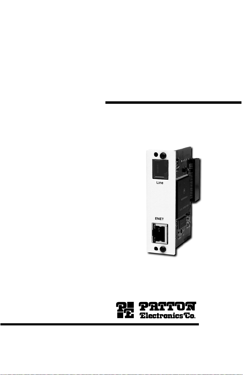
MODEL IM2RC/I-100B
Ethernet Bridge Module
Part# 07MIM2RC -I 100B-UM
Rev. A
Revised 11/26/10
SALES OFFICE
(301) 975-1000
TECHNICAL SUPPORT
(301) 975-1007
Page 2

1.0 Warranty Information ................................................................. 3
1.1 Service.......................................................................................... 3
1.2 Safety When Working With Electricity .......................................... 4
2.0 General Information.................................................................... 6
2.1 Features........................................................................................ 6
2.2 Description.................................................................................... 6
2.3 Typical Application........................................................................ 7
3.0 PPP Operational Background.................................................... 8
3.1 Applications .................................................................................. 8
4.0 Configuration ............................................................................ 10
4.1 Connecting the Interface Driver Board ....................................... 11
5.0 Installation................................................................................. 12
5.1 The Model 1001R14 rack chassis .............................................. 12
The Rack Power Supply ............................................................. 12
5.2 Installing the Rear IM2RC/I-100B Card and Front Function Card...
13
5.3 Connecting to the 10/100Base-T Ethernet port.......................... 14
5.4 Connecting the Line Interface..................................................... 15
6.0 Operation................................................................................... 16
6.1 Operating Instructions.................... ...... ....................................... 16
6.2 Power-Up.................................................................................... 16
6.3 LED status Monitors ................................................................... 16
A
Specifications ........................................................................... 17
A.1 LAN Connection ......................................................................... 17
A.2 Line Connection .......................................................................... 17
A.3 Protocol ....................................................................................... 17
A.4 MAC Address Aging ................................................................... 17
A.5 On-Board Memory ...................................................................... 17
A.6 Interface ...................................................................................... 17
A.7 LED Indicators ............................................................................ 17
A.8 Power Consumption .................................................................... 17
A.9 Temperature Range .................................................................... 17
A.10 Dimensions ................................................................................. 17
2
Page 3

1.0 WARRANTY INFORMATION
Patton Electronics warrants all Model IM2RC/I-100B components to be
free from defects, and will—at our option—repair or replace the product
should it fail within one year from the first date of the shipment.
This warranty is limited to de fects in workmansh ip or materials, a nd does
not cover customer damage, abuse or unauthorized modification. If this
product fails or do es not perfo rms as warrante d, you r so le reco urse shal l
be repair or replacement as described above. Under no condition shall
Patton Electronics be liable for any damages incurred by the use of this
product. These dama ges include , but are not limite d to, the follow ing: lost
profits, lost savings and incidental or consequential damages arising
from the use of or inability to use this product. Patton Electronics spe-
cifically disclaims all other warranties, expressed or implied, and the
installation or use of this product shall be deemed an acceptance of
these terms by the user.
1.1 SERVICE
All warranty and non-warra nty repairs must be returned freight prepaid
and insured to Patton Electro nic s. All retu rns mus t hav e a Ret urn M ate rials Authorization number on the outside of the shipping container. This
number may be obtained from Patton Electronics Technical Services at:
•Tel: +1 (301) 975-1007
•Email: support@patton.com
• URL: http://www.patton.com
Note Packages received without an RMA number will not be
accepted.
3
Page 4

1.2 SAFETY WHEN WORKING WITH ELECTRICITY
• Do not open the device when the power cord is connected. For systems without a power switch and
without an external power adapter, line voltages
are present within the device when the power cord
is connected.
• For devices with an external power adapter, the
power adapter shall be a listed Limited Power
Source The mains outlet that is utilized to power
the device shall be within 10 feet (3 meters) of the
device, shall be easily accessible, and protected
by a circuit breaker in compliance with local regulatory requirements.
• For AC powered devices, ensure that the power
cable used meets all applicable standards for the
country in which it is to be installed.
• For AC powered devices which have 3 conductor
power plugs (L1, L2 & GND or Hot, Neutral &
Safety/Protective Ground), the wall outlet (or
WARNING
socket) must have an earth ground.
• For DC powered devices, ensure that the interconnecting cables are rated for proper voltage, current, anticipated temperature, flammability, and
mechanical serviceability.
• WAN, LAN & PSTN ports (connections) may have
hazardous voltages present regardless of whether
the device is powered ON or OFF. PSTN relates to
interfaces such as telephone lines, FXS, FXO, DSL,
xDSL, T1, E1, ISDN, Voice, etc. These are known
as “hazardous network voltages” and to avoid
electric shock use caution when working near these
ports. When disconnecting cables for these ports,
detach the far end connection first.
• Do not work on the device or connect or disconnect
cables during periods of lightning activity.
4
Page 5

WARNING
WARNING
CAUTION
This device contains no user serviceable parts. This device can
only be repaired by qualified service personnel.
This device is NOT intended nor approved for connection to the
PSTN. It is intended only for connection to customer premise
equipment.
Electrostatic Discharge (ESD) can damage equipment and impair
electrical circuitry. It occurs when electronic printed circuit cards
are improperly handled and can result in complete or intermittent
failures. Do the following to prevent ESD:
• Always follow ESD prevention procedures when removing and
replacing cards.
• Wear an ESD-preventive wrist strap, ensuring that it makes
good skin contact. Connect the clip to an unpainted surface of
the chassis frame to safely channel unwanted ESD voltages
to ground.
• To properly guard against ESD damage and shocks, the wrist
strap and cord must operate effectively. If no wrist strap is
available, ground yourself by touching the metal part of the
chassis.
In accordance with the requirements of council directive 2002/96/EC on Waste of Electrical and Electronic
Equipment (WEEE), ensure that at end-of-life you separate this product from other waste and scrap and deliver
to the WEEE collection system in your country for recycling.
5
Page 6

2.0 GENERAL INFORMATION
Thank you for your purchase of this Patton Electronics product. This
product has been thoroughly inspected and tested and is warranted for
One Y ea r parts and labor. If any questions arise during in stall ation or use
of this product, please contact Patton Electronics Technical Support at:
(301) 975-1007.
2.1 FEATURES
• Installs in Patton’s NetLink Rack Systems
• Provides MAC level connection between two peered Ethernet LANs
• RJ-45 line connection
• Operates transparently to higher level protocols such as TCP/IP,
DECnet, NETBIOS and IPX
• PPP (RFC 1661) with Bridging Control Protocol (RFC 1638)
• No configuration necessary
• Automatically discovers, loads and deletes MAC addresses
• Modular 10/100Base-T co nne cti on (R J-4 5)
• Two LED indicators: status & link integrity
2.2 DESCRIPTION
The Patton IM2RC/I-100B, Et hernet Bridge Mo dule inst alls in the NetL ink
Rack system to provide seamless Ethernet LAN extension. The Patton
IM2RC/I-100B performs the bridging function between two physically
separate Ethernet LANs at the MAC level. Operation of the Patton
IM2RC/I-100B is transparent to higher network level protocols such as
TCP/IP, DECnet, NETBIOS and IPX. The Model IM2RC/I-100B is 802.3
compliant and supports PPP (RFC 1661) with Bridging Control Protocol
(RFC 1638).
Once installed in the local Patton NetLink rack, the Patton IM2RC/I-100B
works in a “plu g and play ” manner to forward LAN broadcas ts , mul ticas ts
and frames destine d fo r th e p eere d Et hernet LAN at the remote end (the
Patton base unit at the remote end must be equipped with an IM1/I module). Using the Patton IM2RC/I-100B in conjuction with a G.SHDSL front
card (3088RC) or NTU (2701RC), peered Ethernet LANs can be linked
over leased 2-wire or E1 circuits. The NTU features externally-accessible
DIP switches, loopback diagnostics, SNMP/HTTP remote-management
6
Page 7

capabilities using RocketLink Plug ‘n’ Play, as well as in-band management.
2.3 TYPICAL APPLICATION
The Model IM2RC/I-100B is designed to plug directly into the rear of a
Patton Electronics rack card modem (i.e. Model 3088RC or 2701RC).
The Model IM2RC/I-100B is designed to be used as one of a pair of
units. Figure 1 (below) illustrates a typical Model IM2RC/I-100B installation.
Corporate
Headquarters
Patton Model 3088
LAN
4.6 Mbps
Leased Line
(Model 3088RC or 2701RC)
Rack-Mounted Ethernet
WAN Bridge Module
Figure 1. Typical Model IM2RC/I-100B application
Remote/Satellite
Office
LAN
7
Page 8

3.0 PPP OPERATIONAL BACKGROUND
PPP is a protocol used for multi-plexed transport over a point-to-point
link. PPP operates on all full duplex media, and is a symmetric peer-topeer protocol, which can be broken into three main components: 1. A
standard method to encapsulate datagrams over serial links; 2. A Link
Control Protocol (LCP) to establish, configure, and test the data-link connection; 3. A family of Network Control Protocols (NCPs) to establish and
configure different network layer protocols.
In order to establ is h c ommu nic ati ons ov er a poi nt-to-point link, each end
of the PPP link must first announce its capabilities and agree on the
parameters of the link’s operation. This exchange is facilitated through
LCP Configure-Request packets.
Once the link has been established and optional facilities have been
negotiated, PPP will attempt to establish a network protocol. PPP will
use Network Control Protocol (NCP) to choose and configure one or
more network layer protocols. Once each of the network layer protocols
have been configured, datagrams from the established network layer
protocol can be sent over the link. The link will remain configured for
these communications until explicit LCP or NCP packets close the link
down, or until some external event occurs.
The PPP Bridging Control Protocol (BCP), defined in RFC 1638, configures and enables/disables the bridge protocol on both ends of the pointto-point link. BCP uses the same packet exchange mechanism as the
Link Control Protocol (LCP). BCP is a Network Control Protocol of PPP,
bridge packets may not be exchanged until PPP has reached the network layer protocol phase.
3.1 APPLICATIONS
In situations where a routed network requires connectivity to a remote
Ethernet network, the interface on router can be configured as a PPP IP
Half Bridge. The serial line to the remote bridge functions as Virtual
Ethernet interface, effectively bridge functions as a Virtual Ethernet interface, effectively extending the routers serial port connection to the
remote network. The br idge device sends bridge p acket s (BPDU’s) to the
router’s serial interface. The router will receive the layer three address
information and will forward these packets based on its IP address.
Figure 2 on page 9 shows a typical Cisco router with a serial interface
configured as a PPP Half Bridge. The router serial interface uses a
remote device that supports PPP bridging to functions as a node on the
remote Ethernet network . the serial inte rface on the C isco wil l have an IP
address on the same Ethernet subnet as the bridge.
8
Page 9

Figure 2. Cisco router with serial interface, configured as PPP Half Bridge
For example, the customer site is assigned the addresses 192.168.1.1
through 192.168.1.254. The address 192.168.1.1 is also the default
gateway for the remote ne tw ork . The abov e s etti ngs rem ov e an y rou tin g/
forwarding intelligence from the CPE. The associated Cisco configuration will set serial interface (s0) to accommodate half bridging for the
above exam ple.
Authentication is optional under PPP. In a point-to-point leased-line link,
incoming customer fa ci lit ies are usually fixed in nature, therefore authe ntication is generally not required. The IM2RC/I-100B does not require
authentication. It also does not respond to authentication requests.
Some networking systems do not define network numbers in packets
sent out over a network. If a packet does not have a specific destination
network number, a router will assume that the packet is set up for the
local segment and will no t forw ard it to any oth er su b-ne twork . H owev er,
in cases where two devices need to communicate over the wide-area,
bridging can be used to transport non-routable protocols.
Figure 3 illustrates transparent bridging between two routers over a
serial interface (s0). Bridging will occur between the two Ethernet Interfaces on Router A (e0 and e1) an d the two Ethernet Int erfaces on Rout er
B (e0 and e1).
Figure 3. Transparent bridging between two routers over a serial link.
9
Page 10

4.0 CONFIGURATION
The Model IM2RC/I-100B module plugs into Patton’s 3088RC and
2701RC modems to provide Ethernet LAN extension. The IM2RC/I100B has no switches or jumpers and does not need to be configured.
However , fac tors suc h as the type of mediu m, through put acros s the link
and clocking mode must be determined by the settings of the baseband
modems. Please refer to your baseband modem (i.e. 3088RC and
2701RC) to make the following settings.
1. Bit Rate: The DTE rate setting of y our base un it corr espond s to the
throughput of your IM2R C/I-100B bri dge module. Use higher spe eds
to allow maximum throughput to your extended LAN. Use lower
speeds to limit the access of your extended LAN.
Note The IM2RC/I-100B only supports synchronous speeds.
2. Clocking Mode: Set the clocking modes on the base units so that
one unit is conf igured for Internal c locking mode and the other u nit is
set for Receive Recover clocking mode.
BASE UNIT CLOCK MODES
Unit “A” Unit “B”
Internal Clock Setting Receive/Recover Clock Setting
Note Unit “A” and Unit “B” are arbitrarily chosen. It does not mat-
ter which unit is “A”, and which is “B”.
3. When using the IM2RC/I-100B, DISABLE, the “Enable Loop from
DTE” Switch on the front function card (3088RC or 2701RC).
4. All other base u nit s ettings depe nd up on yo ur app licat ion and on the
application medium (twisted pair or coaxial cable).
10
Page 11

4.1 CONNECTING THE INTERFACE DRIVER BOARD
This package co nta ins an int erface driver board tha t allows you to confi gure your front function card for ethernet operation. Figure 4 shows the
Interface Driver Boar d co nnected to a Model 2701RC front function card.
Figure 4. Model IM2RC/I-100B Driver Board mounted on Model 2701RC
Follow the instruction s be low to connect the interface driver board to the
front function card:
1. With the function card (such as 27 01RC, shown above) pulled o ut of
the NetLink rack or clusterb ox chass is, locate the dri ve r board to be
replaced on the top of the base unit front card.
2. Lift the old interface board gently off of the printed circuit board.
3. Position the IM2RC/I- 100B driv er board o n top of the function ca rd’ s
pc board with the sockets oriented toward the male pins. Please be
sure the label marked FRONT <– is pointed toward the front of the
function card (toward the LEDs).
4. Push the Interface Driver Board g ently onto the socket and re -ins t a ll
the function card into the rack or cluster system.
11
Page 12

5.0 INSTALLATION
This section describes the NetLink Model 1001R14 rack chassis.
Included are inst allation instru ctions for the IM2RC/I -100B rear card, plus
ethernet and line interface connections to the IM2RC/I-100B card.
Please refer to the appropriate function card (i.e. 3088RC) user manual
to configure and install the function card.
5.1 THE MODEL 1001R14 RACK CHASSIS
The Model 1001R14 Rack Chassis (Figure 5) has fourteen short range
modem card slots, plus its own power supply. Measuring only 3.5” high,
the Model 1001R14 is designed to occupy only 2U in a 19” rack. Sturdy
front handles allow the Model 1001R14 to be extracted and transported
conveniently.
Figure 5. Model 1001R14 Rack Chassis with power supply
The Rack Power Supply
The Patton NetLink rack s ystem is design ed to allo w single or redund ant
(dual) power supplies. Using the same mid-plane architecture as the
function/rear cards, the front function card and the power supply slide in
from the front, while the rear c ard a nd p ow er e ntry modules slide in from
the rear . They pl ug in to one another in the middle of the rack. The front
card is then secure d b y th um b sc rews an d the rear card by conventional
metal screws..
There are no user-serviceable parts in the power supply
section of the Model 1001R14. Voltage setting changes
and fuse replacement should only be performed by
WARNING
qualified service personnel. Contact Patton Electronics
Technical support at (301) 975-1007 for more information.
12
Page 13

5.2 INSTALLING THE REAR IM2RC/I-100B CARD AND FRONT
FUNCTION CARD
The Model IM2RC/I-100B is a rear-mountable ethernet interface card
that works with Patton Models 3088RC and 2701RC access products.
The two cards meet inside the rack chassis and plug into each other by
way of mating 50 pin card ed ge connecto rs. Use th e following step s as a
guideline for installing each Model IM2RC/I-100B and its function card
mate into the rack chassis:
The IM2RC/I-100B card contains sensitive integrated
circuitry. Failure to ground yourself during installation
CAUTION
1. Slide the IM2RC/I-100B rear card into the back of the ch ass is alo ng
the metal rails provided.
2. Secure the IM2RC/I-100B rear card using the metal screws pro-
vided.
3. Slide the front function card into the front of the chassis. It should
meet the IM2RC/I-100B rear card when it is almost all the way into
the chassis.
may result in damage to the IM2RC/I-100B-100B card or
the front function card.
4. Push the front card gently into the card-edge receptacle of the rear
card. It should “click” into place.
5. Secure the front card using the thumb screws.
13
Page 14

5.3 CONNECTING TO THE 10/100BASE-T ETHERNET POR T
The Model IM2RC/I-10 0B pr ovides line s ide c onnec tions through a term inal block or through a RJ-45 connector. Figure 6 below shows the rear
panel and the locations of the connectors.
RJ-45
Line Side
10/100-BaseT
Connector
Figure 6. IM2RC/I-100B Rear Panel
The IM2RC/I-100B Ethernet inte rface is designed to connect dire ctly to a
10/100Base-T network. Figure 7 shows the signal/pin relationships on
this interface. You may connect this port to a hub or PC using a straight
through or crossover cable that is up to 330 feet long.
Figure 7. IM2RC/I-100B Ethernet Connector Pinout
14
Page 15

5.4 CONNECTING THE LINE INTERFACE
The Model IM2RC/I-100 B is to b e us ed w ith Patto n fu nc tion ca rd a cc es s
products (i.e. 3088RC) There are two essential requirements for connecting the line interface on Model IM2RC/I-100B:
1. These units work in pairs with one IM2RC/I-100B connected to
another IM2RC/I-100B over 2 or 4-Wire Twisted pair (2 or 4-Wire
operation is determined by the front function card).
2. To function properly, the Model IM2RC/I-100B needs one or two
twisted pairs of metallic wire (two or four wire). The twisted pairs
must be unconditioned, dry, metallic wire, between 19 (.9mm) and
26 AWG (.4mm) (Appendix B describes cable requirements). Standard dial-up telephone circuits, or leased circuits that run through
signal equalization equipment, or standard, flat modular telephone
type cable, are not acceptable.
Figure 8. RJ-45 Line Interface
Note Two-wire modems use RJ-45 pins 4 and 5 and 4-wire modems
use RJ-45 pins 3, 4, 5 and 6, as shown above. Refer to the
Function Card User Manual for more details.
15
Page 16

6.0 OPERATION
Once the Model IM2RC/I-100B is installed, it should operate transparently. The following sections describes the power-up, general operating
instructions, and the LED status monitors.
6.1 OPERATING INSTRUCTIONS
In order to operate, the Model IM2RC/I-100B must be installed in the
rack unit. It also requires a 10/100Base-T connection. After power is
applied, the IM2RC/I-100B automatically starts performing the bridging
function without further user intervention. MAC addresses discovered
are automatically lo ade d i nto the MAC address table. They are aut om atically deleted from the MAC a ddress t abl e if th ey ex perien ce an inac tivity
of 8 minutes.
6.2 POWER-UP
The Model IM2RC/I-100B is a hot-swappable rear card that receives
power from the NetLink rack power bus. Therefore, it is powered up as
soon it is plugged into the rack and the rack power supply is turned on.
6.3 LED STATUS MONITORS
The Model IM2RC/I-100B features two LEDs that monitor the link and
activity status of the 10/100BaseT interface. Figure 9 (below) shows the
LEDs located directly beneath the RJ-45 jack.
Activity LED
Yellow
Link LED
Green
Figure 9. IM2R C/I-100B Rear Panel, LED Locations
16
Page 17

APPENDIX A
SPECIFICATIONS
A.1 LAN CONNECTION
RJ-45, 10/100Base-T, 802.3af Ethernet
A.2 LINE CONNECTION
RJ-45, female connector
A.3 PROTOCOL
PPP (RFC 1661) with Bridging Control Protocol (RFC3518)
A.4 MAC ADDRESS AGING
MAC addresses deleted after 6 minutes inactivity
A.5 ON-BOARD MEMORY
128MB DDR2 SDRAM; 16MB FLASH
A.6 INTER FACE
Card-edge connection to Patton modems
A.7 LED INDICATORS
(1) general status; (1) link integrity
A.8 POWER CONSUMPTION
200mA @ 12VDC, supplied by chassis power supply
A.9 TEMPERATURE RANGE
32 to 122ºF (0 to 50º C)
A.10 DIMENSIONS
2.04” x 3.24” (5.2 mm x 8.26 mm)
17
Page 18

NOTES
_______________________________________________________
_______________________________________________________
_______________________________________________________
_______________________________________________________
_______________________________________________________
_______________________________________________________
_______________________________________________________
_______________________________________________________
_______________________________________________________
_______________________________________________________
_______________________________________________________
_______________________________________________________
_______________________________________________________
_______________________________________________________
_______________________________________________________
_______________________________________________________
_______________________________________________________
_______________________________________________________
_______________________________________________________
_______________________________________________________
_______________________________________________________
_______________________________________________________
_______________________________________________________
_______________________________________________________
18
Page 19

NOTES
_______________________________________________________
_______________________________________________________
_______________________________________________________
_______________________________________________________
_______________________________________________________
_______________________________________________________
_______________________________________________________
_______________________________________________________
_______________________________________________________
_______________________________________________________
_______________________________________________________
_______________________________________________________
_______________________________________________________
_______________________________________________________
_______________________________________________________
_______________________________________________________
_______________________________________________________
_______________________________________________________
_______________________________________________________
_______________________________________________________
_______________________________________________________
_______________________________________________________
_______________________________________________________
_______________________________________________________
19
Page 20

© Copyright 2010.
Patton Electronics Company
All Rights Reserved
20
 Loading...