

Page 1
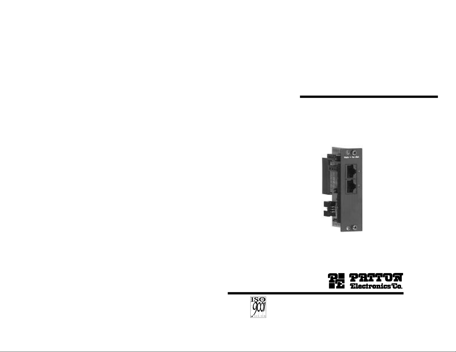
USER
MANUAL
MODEL IM2RC/F
64k Co-Directional Rack Mount
Modem Rear Card
Part# 07MIM2RC/F-A
Doc# 078411UA
Revised 5/4/98
An ISO-9001
Certified Company
SALES OFFICE
(301) 975-1000
TECHNICAL SUPPORT
(301) 975-1007
http://www.patton.com
Page 2

TABLE OF CONTENTS
1.0 WARRANTY INFORMATION
Section Page
1.0Warranty Information.............................................................2
1.1Radio and TV Interference
1.2CE Notice
1.3 Service Information
2.0General Information...............................................................4
2.1Product Features
2.2General Product Description
3.0Configuration.........................................................................5
3.1 Configuring the IM2RC/F Hardware Switches
3.2 Connecting the Interface Driver Board
4.0Installation.............................................................................9
4.1The Model 1000R16 Rack Chassis
4.2Installing the Rear IM2RC/F Card and Front Function Card
4.3 Making Interface Connections
5.0Operation.............................................................................14
5.1Typical Application
5.2Operating Instructions
Appendix A - Specifications........................................................15
Appendix B - Factory Replacement Parts and Accessories.......16
Appendix C - 120 Ohm G.703 Inteface Pin Assignment.............17
Appendix D - Line Interface Assignment....................................18
Patton Electronicswarrants all Model IM2RC/F components to
be free from defects, and will—at our option—repair or replace the
product should it fail within one year from the first date of shipment.
This warranty is limited to defects in workmanship or materials,
and does not cover customer damage, abuse or unauthorized
modification. If this product fails or does not perform as warranted,
your sole recourse shall be repair or replacement as described above.
Under no condition shallPatton Electronicsbe liable for any damages
incurred by the use of this product. These damages include, but are
not limited to, the following: lost profits, lost savings and incidental or
consequential damages arising from the use of or inability to use this
product. Patton Electronicsspecifically disclaims all other warranties,
expressed or implied, and the installation or use of this product shall be
deemed an acceptance of these terms by the user.
1.1RADIO AND TV INTERFERENCE
The Model IM2RC/F generates and uses radio frequency energy,
and if not installed and used properly—that is, in strict accordance with
the manufacturer's instructions—may cause interference to radio and
television reception. The Model IM2RC/F has been tested and found to
comply with the limits for a Class A computing device in accordance
with the specifications in Subpart J of Part 15 of FCC rules, which are
designed to provide reasonable protection from such interference in a
commercial installation. However, there is no guarantee that
interference will not occur in a particular installation. If the Model
IM2RC/F does cause interference to radio or television reception,
which can be determined by disconnecting the unit, the user is
encouraged to try to correct the interference by one or more of the
following measures: moving the computing equipment away from the
receiver, re-orienting the receiving antenna and/or plugging the
receiving equipment into a different AC outlet (such that the computing
equipment and receiver are on different branches). In the event the
user detects intermittent or continuous product malfunction due to
nearby high power transmitting radio frequency equipment, the user is
strongly advised to use only data cables with an external outer shield
bonded to a metal or metalized connector at both ends. Shielded
cables must be used on the network connection to satisfy compliance
with the Electromagnetic Compatibility (EMC) directive.
1
2
Page 3

1.2CE NOTICE
The CE symbol on your Patton Electronics equipment indicates
that it is in compliance with the Electromagnetic Compatibility (EMC)
directive and the Low Voltage Directive (LVD) of the Union European
(EU). A Certificate of Compliance is available by contacting Technical
Support.
2.0 GENERAL INFORMATION
Thank you for your purchase of this Patton Electronics product.
This product has been thoroughly inspected and tested and is
warranted for One Year parts and labor. If any questions arise during
installation or use of this product, please contact Patton Electronics
Technical Support at: (301) 975-1007.
1.3SERVICE
All warranty and non-warranty repairs must be returned freight
prepaid and insured to Patton Electronics. All returns must have a
Return Materials Authorization number on the outside of the shipping
container. This number may be obtained from Patton Electronics
Technical Services at:
Telephone: (301) 975-1007;
Web Address: http://www.patton.com;
email: support@patton.com.
NOTE:Packages received without an RMA number will not be
accepted.
Patton Electronics' technical staff is also available to answer any
questions that might arise concerning the installation or use of your
Model IM2RC/F. Technical Service hours: 8AM to 5PM EST, Monday
through Friday.
2.1 FEATURES
• Designed for use with Patton Electronics short range modem
access products that receive Patton’s Rear Card modules and
support 64k/128k synchronous data rates
• Compliant with ITU-T G.703 electrical specifications
• 120 ohm RJ-45 Network Termination
• Complies with ITU-T G.823 Jitter Control Specifications
• Supports Clear Channel or Octet Timing Modes
• Built-in Transformer Isolation and Surge Protection
• Supports Network or Modem Timing
• Fits in Patton’s 2u (3.5”) rack chassis and cluster boxes
• Made in the U.S.A.
2.2 DESCRIPTION
The Patton Model IM2RC/F is a rack-mountable rear card that
provides Patton baseband modems with an interface to the G.703
PCM network. With the IM2RC/F you can achieve high speed G.703
network extension, dedicated high speed internet access, remote LAN
access,...the possibilites are endless! Supporting 64 kbps clear
channel or 128 kbps octet mode data streams, the IM2RC/F can set its
own clock or it take clocking from the G.703 network.
The Model IM2RC/F meets baseband modem function cards such
as 1092ARC, 1045RC and 2500RC in the mid-plane of Patton’s 2U
(3.5”) rack chassis. G.703 access is accomplished via a 120 Ohm RJ45 jack. 2 or 4 Wire twisted pair Line connections are made via a
second RJ-45 jack.
The Model IM2RC/F features on-board transformer isolation and
surge protection as well as compliance with ITU-T G.823 Jitter Control
Specifications.
3
4
Page 4
3.0 CONFIGURATION
This section describes how to configure the IM2RC/F rear card.
Please refer to the appropriate function card user manual to configure
the function card.
WARNING!The IM2RC/F card contains sensitive
integrated circuitry. Failure to ground yourself during
configuration may result in damage to the IM2RC/F card or
the front function card.
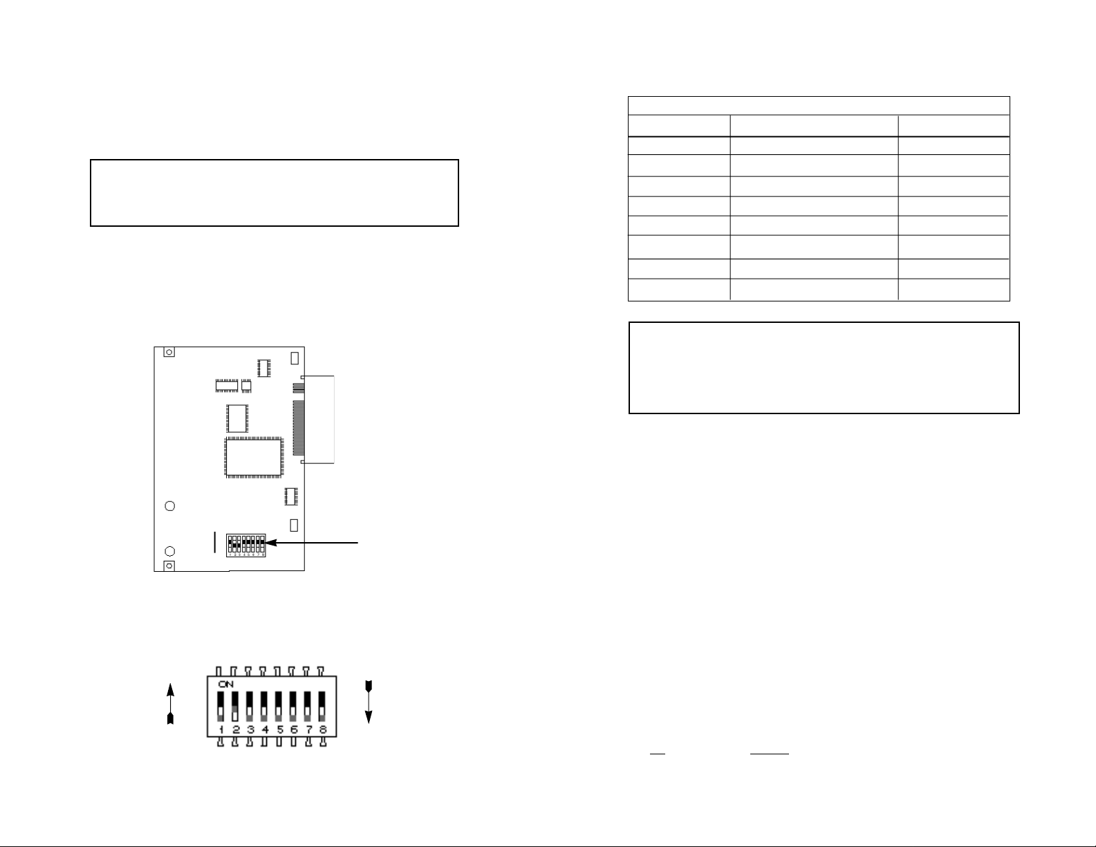
3.1 CONFIGURING THE IM2RC/F HARDWARE SWITCHES
The Model IM2RC/F rear card features an eight position DIP switch
mounted on the rear of the printed circuit board. Use these switches to
configure G.703 operational and timing modes. Figure 1, below shows
the position of the DIP switches on the board.
SWITCH SUMMARY TABLE
Position Function Factory Default
S1 Reserved for Future Use Off
S2 Operation Mode Off Clear Channel
S3 Timing Mode OffNetworkTiming
S4 Reserved for Future Use Off
S5 Reserved for Future Use Off
S6 G.703 Transmit Octet Off Injected BPVs
S7 Reserved for Future Use Off
S8 Reserved for Future Use Off
Notice!The RJ-45 G.703 port of the Model IM2RC/F is
intended to connect to telecommunication network voltage
(TNV) circuits which may carry dangerous voltages. Therefore
the power and network cables must be disconnected prior to
switch configuration.
Switch S1: Reserved for Future Use
Switch S1 is reserved for future use and should remain in the Off
position.
ON
DIP Switches
OFF
Figure 1. Model IM2RC/F Card Showing DIP Switches
Figure 2 shows the orientation of the DIP switches with respect to
the “ON” and “OFF” positions.
ON
OFF
Figure 2. Close up of Configuration switches
5
Switch S2: Operation Mode
Use Switch S2 to set the IM2RC/F for either Clear Channel or
Octet Timing Mode. Most installations use Clear Channel (64kbps)
Mode operation, though some installations may use Octet Timing
Mode.
When operating in octet timing mode, the IM2RC/F facilitates a
sense of frame synchronization by inserting bi-polar violations in the
AMI conding structure. When the IM2RC/F is set to Octet Timing Mode
(On position), all communications equipment in the channel must be
configured to communicate at 128 kbps (64 kbps data plus 64 kbps
octet framing pattern) Additionally, all terminal equipment must support
octet timing. When set to Clear Channel Mode, the system operates at
64 kbps.
S2 Setting
Off Clear Channel Mode
On Octet Timing Mode
6
Page 5

Switches S3 Timing Mode
3.2 CONNECTING THE INTERFACE DRIVER BOARD
The setting of Switch S3 determines the source of the system timing.
The system timing may be provided by:
1. The G.703 network;
2. The local function card or remote baseband
modem/CSU/DSU (either a rackable function card or standalone unit).
Set Switch S3 to “Network” timing when only one of the two
connected baseband modems or CSU/DSUs employ a 64k/G.703
interface card (the “other” baseband modem connects to a V.35, EIA-
232, etc device).
Set Switch S3 to “Modem” timing when both of the connected
baseband modems or CSU/DSUs employ a 64k/G.703 interface card.
In this application, one G.703 interface card must be set to “Modem”
timing, and the other must be set to “Network” Timing. (Please refer to
the baseband modem or CSU/DSU user manual for additional
configuration details).
Switches S4 and S5: Reserved for Future Use
Switches S4 and S5 are reserved for future use and should remain
in the Off position.
This package contains an interface driver board that allows you to
configure your front function card for G.703 operation. Figure 3 shows
the Interface Driver Board connected to a Model 1092ARC front
function card (You may also use this product with other Patton rack
cards, such as Model 2500RC, 1045RC or 1092RC).
Model
1092ARC
Figure 3 Model IM2RC/F Driver Board mounted on Model 1092ARC
Interface Driver Board
FRONT
Follow the instructions below to connect the interface driver board
to the front function card:
Switch S6: Operation Mode
In some cases it is necessary to include bi-polar violations in the
AMI structure when operating in Clear Channel (64 kbps) mode. This
necessity is determined by communications or terminal equipment
external to the the IM2RC/F. Use Switch S6 to configure the unit to
transmit G.703 data to the network with or without BPVs.
S6 Setting
On No BPVs
Off Injected BPVs
Switches S7 and S8: Reserved for Future Use
Switch S7 and S8 are reserved for future use and should remain in
the Off position.
7
1. With the function card (such as 1092ARC, shown above)
pulled out of the rack or clusterbox chassis, locate the driver
board to be replaced on the top of the base unit front card.
2. Lift the old interface board gently off of the PC board.
3. Position the IM2RC/F driver board on top of the function card’s
pc board with the sockets oriented toward the male pins.
Please be sure the label marked FRONT is pointed
toward the front of the function card (toward the LEDs).
4. Push the Interface Driver Board gently onto the socket and reinstall the function card into the rack or cluster system.
8
Page 6

4.0 INSTALLATION
This section describes the functions of the Model 1000R16 rack
chassis, tells how to install the rear-mounted Model IM2RC/F card into
the chassis, and how to connect to the G.703 PCM network, and to the
twisted pair line interface. Please refer to the appropriate function card
user manual for further details.
NOTE: Please refer to the Model 1000RP Series User Manual AC
and DC Rack Mount Power Supplies for fuse and power card
replacement information.
4.2INSTALLING THE REAR IM2RC/F CARD AND FRONT
FUNCTION CARD
4.1 THE MODEL 1000R16 RACK CHASSIS
The Model 1000R16 Rack Chassis (Figure 4, below) has sixteen
baseband modem card slots, plus its own power supply. Measuring
only 3.5” high, the Model 1000R16 is designed to occupy only 2U in a
19” rack. Sturdy front handles allow the Model 1000R16 to be
extracted and transported conveniently.
Figure 4: Model 1000R16 Rack Chassis with power supply
4.1.1 The Rack Power Supply
The power supply included in the Model 1000R16 rack uses the
same mid-plane architecture as the function cards. The front function
card and the power supply slide in from the front, while the rear card
and power entry modules slide in from the rear. They plug into one
another in the middle of the rack. The front card is then secured by
thumb screws and the rear card by conventional metal screws.
The Model IM2RC/F is a rear-mountable G.703 interface card that
works with Patton function card access products that support 64k/128k
synchronous data rates. The two cards meet inside the rack chassis
and plug into each other by way of mating 50 pin card edge
connectors. Use the following steps as a guideline for installing each
Model IM2RC/F and its function card mate into the rack chassis:
WARNING!The IM2RC/F card contains sensitive
integrated circuitry. Failure to ground yourself during
installation may result in damage to the IM2RC/F card or
the front function card.
1. Slide the IM2RC/F rear card into the back of the chassis along
the metal rails provided.
2. Secure the IM2RC/F rear card using the metal screws
provided.
3. Slide the front function card into the front of the chassis. It
should meet the IM2RC/F rear card when it is almost all the
way into the chassis.
4. Push the front card gentlyinto the card-edge receptacle of the
rear card. It should “click” into place.
5. Secure the front card using the thumb screws.
WARNING!There are no user-serviceable parts in the
power supply section.Voltage setting changes and fuse
replacement should only be performed by qualified
service personnel. Contact Patton Electronics Technical
support at (301)975-1007 for more information.
9
10
Page 7

4.3 MAKING INTERFACE CONNECTIONS
4.3.2 CONNECTING THE LINE INTERFACE
The Model IM2RC/F is designed to provide access to a 64 kbps
co-directional G.703 PCM network. Figure 5 shows the position of the
G.703 interface and the line interface of the IM2RC/F. This section
describes how to connect the G.703 interface and the line interface.
Notice!The G.703 line surge protection on this unit was
installed for circuit protection only. By no means does this
include the preservation of signal quality during a large surge.
RJ-45 Line Interface
120 Ohm RJ-45
G.703 Interface
Figure 5: Model IM2RC/F Interface Ports
4.3.1 CONNECTING TO A G.703 PCM NETWORK CHANNEL
The 120 Ohm RJ-45 port on a Model IM2RC/F is pre-wired for
direct connection to the G.703 PCM network. Connect the RJ-45 jack
provided by your digital service carrier to the 120 Ohm G.703 interface
on the Model IM2RC/F using a straight through twisted pair cable
between 19 and 26 AWG (0.4mm to .9mm, inversely). To be sure you
have the right wiring, refer to Figure 6, below.
1 (RX+)
1
2
3
4
5
6
7
8
2 (RX-)
3 (N/C)
4 (TX-)
5 (TX+)
6 (N/C)
7 (N/C)
8 (N/C)
The Model IM2RC/F is to be used with Patton function card access
products (i.e. 1045RC, 1092RC, 1092ARC, 2500RC) that support
64k/128k synchronous data rates. There are two essential
requirements for connecting the line interface on Model IM2RC/F:
1. These units work in pairs. Both units at the end of the twisted
pair must have the proper 2-Wire/4-Wire setting. For
instance, if you are operating in 2-Wire mode, both units must
be in the 2-Wire setting. Similarly, if you are operating in 4Wire mode, both units must be in the 4-Wire setting. NOTE:
Currently only the 1092 and 1092A families support 2-Wire
Mode.
2. To function properly, the Model IM2RC/F needs one or two
twistedpairs of metallic wire. The twisted pairs must be
unconditioned, dry, metallic wire, between 19 (.9mm) and 26
AWG (.4mm) (Appendix B describes cable requirements) .
Standard dial-up telephone circuits, or leased circuits that run
through signal equalization equipment, or standard, flat
modular telephone type cable, are not acceptable. Figure 7,
below, shows the pin/signal relationships of the Line Interface
Port.
1 (4-Wire RX+)
2 (4-Wire RX-)
1
2
3
4
5
6
7
8
3 (no connection)
4 (2-Wire TIP)/(4-Wire TX+)
5 (2-Wire RING)/(4-Wire TX-)
6 (no connection)
7 (no connection)
8 (no connection)
Figure 7: RJ-45 Line Interface
Figure 6: 120 Ohm RJ-45 G.703 Interface
11
12
Page 8

4.3.3 Two-Wire and Four-Wire Cable Connection Via RJ-45
1. The Line Interface Port on the Model IM2RC/F’s twisted pair
interface is polarity insensitive and is wired for a two-wire
interface.
2. Proper
2-WirePairingbetween the two modems is as follows:
SIGNAL PIN# PIN# SIGNAL
TIP 4---------------------------------------------4 TIP
RING 5---------------------------------------------5 RING
3. Proper
4-WirePairing between the two modems is as follows:
SIGNAL PIN# PIN# SIGNAL
Tx 4---------------------------------------------3 Rx
Tx 5---------------------------------------------6 Rx
Rx 3---------------------------------------------4 Tx
Rx 6---------------------------------------------5 Tx
5.0 OPERATION
Once the Model IM2RC/F is installed and configured, it should
operate transparently. This sections describes a typical application
and general operating instructions.
5.1 TYPICAL APPLICATION
The Model IM2RC/F allows a remotely connected LAN or high
speed application to connect to the 64k/G.703 (PCM) network through
a pair of Patton baseband modems. Figure 8 (below) shows a typical
application of the IM2RC/F.
Remote Baseband
Modem, CSU/DSU, HDSL
Modem, etc.
G.703
PCM
Network
Rack-Mounted
Baseband Modem, CSU/DSU,
HDSL Modem, etc. with
IM2RC Rear Card
Router
Figure 8: IM2RC/F Typical Application
LAN
NOTE: The pin designations shown above are to be used when
connecting to another IM2RC/F or other similarly pinned line
interface on a Patton rear card. Please review the appropriate
function card user manual or stand-alone product user manual to
determine the correct pin assignments.
Notice!Any G.703 or line interface cable connected to the
Model IM2RC/F must be shielded cable, and the outer shield
must be 360 degree bonded–at both ends–to a metal or
metalized backshell.
13
5.2 OPERATING INSTRUCTIONS
In order to operate, the Model IM2RC/F must be installed in the
rear of a Patton 16 port rack or a 2, 4, or 8 port ClusterBox™ chassis.
A front function card, such as a baseband modem, CSU/DSU, or HDSL
modem meets the IM2RC/F rear card in the mid-plane of the chassis.
The IM2RC/F also requires a G.703 connection to the 64 kbps codirectional PCM networkand a line connection to a remote Patton
transmssion device. After applying power, the function card and
IM2RC/F operate transparently according to the applied settings
(Please refer to the function card manual for further details).
14
Page 9

APPENDIX A
PATTON IM2RC/F
SPECIFICATIONS
APPENDIX B
PATTON IM2RC/F
CABLE RECOMMENDATIONS
Applications: 64kbps G.703 PCM network
extension
G.703 Interfaces: Symmetrically balanced 4-wire, 120 Ohm
RJ-45 jack termination
Line Interface: Entire module plugs into 1092RC,
1092ARC, 2500RC, 1045RC, HDSL Series
Patton transmission devices products
Operating Modes: Supports octet or clear channel mode; co-
directional timing, Rx recovered: 64/128
kbps±500/1000ppm.
Octet timing auto detection on receiver.
Line Encoding: AMI with bi-polar violations for octet timing.
Timing Modes: Modem or network timing
G.703 Input
Signal Level: 0 to -10 dB
Transmit Level: 2.0V differential into 100 Ohms, nominal
Load Impedance: 120 Ohms
Jitter Performance: CTR 14, G.823
Surge Protection: Complies with IEC 801.5 level 1, 500V
Isolation: 1500V RMS isolation, tranformer coupled
PCB Dimensions: 2.04” x 3.24”
Approvals: CE Mark
Compliance: EMC directive: 89/336/ECC
Emissions: EN55022
Immunity: EN50082-1
Low Voltage (LVD) Directive: 73/23/ECC
Safety: EN60950
CTR 14, (Type Approval) - The
symbol indicates that the Model IM2RC/F is
in compliance with the applicable Telecom
Directive of the EU. If your IM2RC/F is
marked with this symbol, it is EU Telecom
Type Approved and may be connected to
the public network.
Power
Consumption: <140mA @ 10 VAC RMS, including
integrated front card modem with the rack
card power supply under full load
Temp. Range: 0 - 60˚ C (32 - 140˚ F)
Altitude Range: Up to 15,000 ft (4572 m)
Humidty Range: 5 - 95% non-condensing
All Patton Electronics Company Baseband Modems, CSU/DSUs
and Short Range Modem are tested to the distances published in our
Catalogs and Specification Sheets on twisted-pair cable with the
following characteristics:
Wire Gauge Capacitance Resistance
19 AWG 83nF/mi or 15.72 pF/ft. .0163Ω/ft.
22 AWG 83nF/mi or 15.72 pF/ft. .0326Ω/ft.
24 AWG 83nF/mi or 15.72 pF/ft. .05165Ω/ft.
26 AWG 83nF/mi or 15.72 pF/ft. .08235Ω/ft.
We fully expect that the Baseband Modems, CSU/DSUs and Short
Range Modems will operate on lines with specifications different from
those tested, but to reduce the potential difficulties in the field, one
should ensure that the cable being used has similar or better
characteristics (lower capacitance or lower resistance).
Wire with capacitance of 20pF/ft. or less is suitable for all Baseband
Modems, CSU/DSUs and Short Range Modems. However, distances
may vary from those published in our catalog. Resistance will also
affect distance but not functionality. Wire should be 26 AWG or larger
(smaller AWG#).
Patton products are designed to withstand normal environmental
noise and conditions; however, other environmental factors too
numerous to discuss in this format may affect proper operation.
Selection of the proper Baseband Modem, CSU/DSU or SRM for an
application is critical to maintaining Customer Satisfaction and must be
taken seriously. Certain models are better suited for particular
applications and environments than others.
15
16
Page 10

APPENDIX C
APPENDIX D
PATTON IM2RC/F
FACTORY REPLACEMENT PARTS
AND ACCESSORIES
Patton Model # Description
1000RCM12592.........Rear card w/DB25F & RJ45 (V.24 interface)
1000RCM12492.........Rear card w/ M/34F & RJ45 (V.35 interface)
1000RPEM................120/240V Rear Power Entry Module
1000RPSM-2.............120/240V Front Power Supply Module
1000RPEM-DC..........DC Rear Power Entry Module
1000RPSM-48A.........48V Front Power Supply Module
1000RPEM-V.............120/240V CE Compliant Rear Power
Entry Module
1000RPEM-V.............120/240V CE Compliant Rear Power
Supply Entry Module
1000CC......................Control Card
1000RCM703/64DB...Interface daughter card, G.703
1180RCDB.................Interface daughter card, V24/V.35
0805US......................American Power Cord
0805EUR...................European Power Cord CEE 7
0805UK......................United Kingdom Power Cord
0805AUS...................Australia/New Zealand Power Cord
0805DEN...................Denmark Power Cord
0805FR......................France/Belgium Power Cord
0805IN.......................India Power Cord
0805IS.......................Israel Power Cord
0805JAP....................Japan Power Cord
0805SW.....................Switzerland Power Cord
IM2RC/F....................G.703 Rear Card
PATTON IM2RC/F
120 OHM G.703 INTERFACE PIN ASSIGNMENT
(RJ45 Female Connector)
Pin Number Signal
1..........................................RX+
2..........................................RX-
3..........................................no connection
4...........................................TX-
5..........................................TX+
6..........................................no connection
7..........................................no connection
8..........................................no connection
17
18
Page 11

APPENDIX E
APPENDIX F
LINE INTERFACE PIN ASSIGNMENT
(RJ45 Female Connector)
Pin Number Signal
1..........................................4-Wire RX+
2..........................................4-Wire RX-
3..........................................no connection
4...........................................2-Wire TIP/4-Wire TX+
5..........................................2-Wire RING/4-Wire TX-
6..........................................no connection
7..........................................no connection
8..........................................no connection
PATTON IM2RC/F
ARCHITECTURE
Copyright 1998
Patton Electronics Company
All Rights Reserved
19 20
 Loading...