

Page 1

MODEL IM 1/J
Voice/Data Module
SALES OFFICE
(301) 975-1000
TECHNICAL SUPPORT
(301) 975-1007
http://www.patton.com
Part# 07MIM1J-A
Doc# 090111UA
Revised 10/16/98
An ISO-9001
Certified Company
USER
MANUAL
Page 2

2
1.2 CE NOTICE
The CE symbol on your Patton Electronics equipment indicates
that it is in compliance with the Electromagnetic Compatibility (EMC)
directive and the Low Voltage Directive (LVD) of the Union European
(EU). To get a Certificate of Compliance, contact Technical Support.
1.3 SERVICE
All warranty and nonwarranty repairs must be returned freight
prepaid and insured to Patton Electronics. All returns must have a
Return Materials Authorization number on the outside of the shipping
container. This number may be obtained from Patton Electronics
Technical Service at: (301) 975-1007, http://www.patton.com;
support@patton.com.
NOTE: Packages received without an RMA number will not be
accepted.
Patton Electronics’ technical staff is also available to answer any
questions that might arise concerning the installation or use of your
Model IM1/J. Technical Service hours: 8AM to 5PM EST, Monday
through Friday.
WARNING! This device is not intended to be
connected to the public telephone network.
11..00 WWAARRRRAANNTTYY IINNFFOORRMMAATTIIOONN
Patton Electronics warrants all IM1/J components to be free from
defects, and will—at our option—repair or replace the product should it
fail within one year from the first date of shipment.
This warranty is limited to defects in workmanship or materials, and
does not cover customer damage, abuse or unauthorized modification.
If this product fails or does not perform as warranted, your sole recourse
shall be repair or replacement as described above. Under no condition
shall Patton Electronics be liable for any damages incurred by the use
of this product. These damages include, but are not limited to, the
following: lost profits, lost savings and incidental or consequential
damages arising from the use of or inability to use this product. Patton
Electronics specifically disclaims all other warranties, expressed or
implied, and the installation or use of this product shall be deemed an
acceptance of these terms by the user.
1.1 RADIO AND TV INTERFERENCE
The Model IM1/J generates and uses radio frequency energy, and if
not installed and used properly—that is, in strict accordance with the
manufacturer’s instructions—may cause interference to radio and
television reception. The Model IM1/J has been tested and complies
with the limits for a Class A computing device in accordance with the
specification in Subpart J of Part 15 of FCC rules, that are designed to
provide reasonable protection from such interference in a commercial
installation. However, this is no guarantee that interference will not
occur in a particular installation. If the Model IM1/J does cause
interference to radio or television reception, which can be determined by
disconnecting the unit, the user is encouraged to try to correct the
interference by one or more of the following measures: moving the
computing equipment away from the receiver, reorienting the receiving
antenna and/or plugging the receiving equipment into a different AC
outlet (such that the computing equipment and receiver are on different
branches). In the event the user detects intermittent or continuous
product malfunction due to nearby high power transmitting radio
frequency equipment, the user is strongly advised to use only a shielded
twisted pair data cable that is bonded to metalized external outer shield
plugs at both ends. The use of a shielded cable satisfies compliance
with the Electromagnetic Compatibility (EMC) directive.
1
Page 3

2.0 GENERAL INFORMATION
Thank you for your purchase of this Patton Electronics product.
This product has been thoroughly inspected and tested and is
warranted for One Year parts and labor. If any questions or problems
arise during installation or use of this product, please do not hesitate to
contact us at (301) 975-1007.
2.1 FEATURES
• Adds two Voice Ports and a Synchronous Data Port to Patton’s
KiloModem Series (Models 1092, 1093, 1094, and 1095)
• Two Loop Start RJ-11 Voice Ports Available as either FXS or FXO
• Synchronous DCE Interface: V.35, RS-232/V.24 or RS-422/530
• Supports Internal Clocking
• Data Rates: 64,192, 320, 448, 704 kbps
• CE and FCC Part 15 Class A Compliant
2.2 DESCRIPTION
Patton's new Voice/Data QuikConnect Module (Model no. IM1/J)
extends the functionality of its KiloModem products by allowing voice,
fax and data traffic to be carried over one transmission circuit. The
VDQM supports user interfaces for G3 fax, synchronous data and
PSTN or compressed voice traffic on one module.
Two RJ11 voice/fax ports support FXS, FXO and G3 fax while using
just 64Kbps of bandwidth. Each VDQM also provides a universal data
port that is user-configurable for V.35, RS232/V.24 and RS-530
interfaces. Inserted in the KiloModem products, the VDQM combines
voice/data/fax traffic onto a typical 2-wire or 4-wire circuit at speeds up
to 768kbps with distances up to 17.4 km.
The VDQM is the perfect solution for connecting remote branches or
satellite offices which require voice, fax and high-speed data
communications. Use a pair of VDQMs to connect a telephone and fax
machine in a remote branch office to a PBX in the head office. Serial
data traffic shares the same 2-wire interface and flows for free !!!
3
3.0 CONFIGURATION
The Model IM1/J VDQM is equipped with three sets of eight DIP
switches, which allow configuration of the unit to a wide variety of
applications. This section describes switch locations and explains all
possible configurations of the VDQM. Please refer to the appropriate
baseband modem (1092, 1093, etc) user manual to configure the
baseband modem.
3.1 CONFIGURING THE HARDWARE DIP SWITCHES
The 24 external switches are grouped into three eight-switch sets,
and are externally accessible from the underside of the VDQM printed
circuit board (See Figure 1).
The three sets of DIP switches on the underside of the Model
VDQM will be referred to as S1, S2, and S3, as shown above. Figure
2, below, shows the “On” and “Off” positions of each switch.
4
1 8
8
1
1
8
ON
OFF
ON OFF
OFF ON
S1
S2
S2
Figure 1. Switches S1, S2, and S3 on the bottom of the VDM
Figure 2. Close Up of Configuration Switches (all sets are identical in appearance)
ON
OFF
Page 4
3.2.1 Setting the Electrical Interface (Switches S1 & S2)
In order to make the VDQM work in your application, you must set
the electrical interface of the synchronous data port. Applicable
electrical interfaces are:
a) V.35
(default setting)
b) EIA-232
c) EIA-422
To set the electrical interface, set Switches S1-1 through S1-8 and
Switches S2-1 through S2-6.
Switches S2-7 and S2-8 are reserved for
future usage and must remain in the OFF position
. The following table
summarizes the VDQM switch settings for each of these interfaces:
NOTE: All of the above electrical interfaces are implemented on a
HD-26 connector). Please refer to Appendix C for the applicable
pin assignments.
5
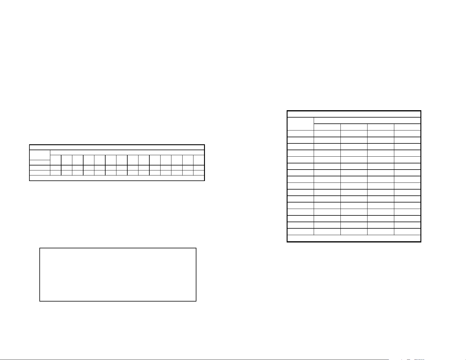
Electrical
S1-1 S1-2 S1-3 S1-4 S1-5 S1-6 S1-7 S1-8 S2-1 S2-2 S2-3 S2-4 S2-5 S2-6
V.35* On On On On Off On On Off On Off Off Of f On On
EIA-232 Off Off Off Off On Off Off On Off On On On On Off
EIA-422 On On On On Off Off On Off Off Off Off Off Off Off
Data Port Electrical Interface Summary Table
* Default Setting
Switch Settings
NOTE: Both voice ports must meet the country of
installation's requirements for a PSTN interface device,
which is typically defined in NET-4. If a country
requirement is not defined in NET-4, it is possible to
configure the phone interface to meet those country
requirements within a month of receiving the specifications
and test criteria from that country.
3.2.2 Setting the DTE Rate (Switches S3-1 through S3-4)
You must also set the bit rate of the VDQM to match the bit rate of
the equipment connected to the DTE port. The following table
summarizes the DTE rate settings of the VDQM.
To set the DTE rate, set Switches S3-1 through S3-4 (
Switches
S3-5 through S3-8 are reserved for future use and must remain in the
OFF position)
.
NOTE: You must also set the applicable DTE rate on the
baseband modem (ie. Model 1092, 1093, etc). Please see the
baseband modem user manual for details. The baseband modem
and the VDQM must be set for the same DTE rate.
6
DTE Rate
(kbps) S3-1 S3-2 S3-3 S3-4
128* Off Off Off Off
256 On Off Off Off
384 Off On Off Off
512 On On Off Off
640 Off Off On Off
768 On Off On Off
896 Off On On Off
1024 On On On Off
1152 Off Off Off On
1280 On Off Off On
1408 Off On Off On
1536 On On Off On
1664 Off Off On On
1792 On Off On On
1920 Off On On On
2048 On On On On
Data Rate Summary Table
Switch Settings
* Default Setting
Page 5
44..00 IINNSSTTAALLLLAATTIIOONN
This section tells you how to install the VDQM
QuikConnect™
module into the baseband modem, as well as how to connect the voice
and the data ports.
4.1 INSTALLING THE
QuikConnect™
MODULE
Each QuikConnect Module™ has a 50-pin card edge connector on
one side and an ethernet interface on the other. The instructions below
describe how to remove the existing QuickConnect™ Module and how
to install the new IM1/I module. If your base unit does not have an
existing QuickConnect™ already installed, please skip to section 4.1.2.
4.1.1 Removing the Existing
QuikConnect™
Module
1) Turn the power switch off. Leave the power cord plugged into a
grounded outlet to keep the unit grounded.
2) Loosen the two thumbscrews on the module by turning them
counterclockwise.
3) Grasp the two thumbscrews and gently pull the module from the
unit. Apply equal force to the thumbscrews to keep the module
straight during the removal process
7
4.1.2 Installing the New
QuikConnect™
Module
1) Make sure the power switch on the base unit is off. Leave the
power cord plugged into a grounded outlet to keep the unit
grounded.
2) Hold the module with the faceplate toward you and align the
module with the guide slots in the rear panel of the base unit.
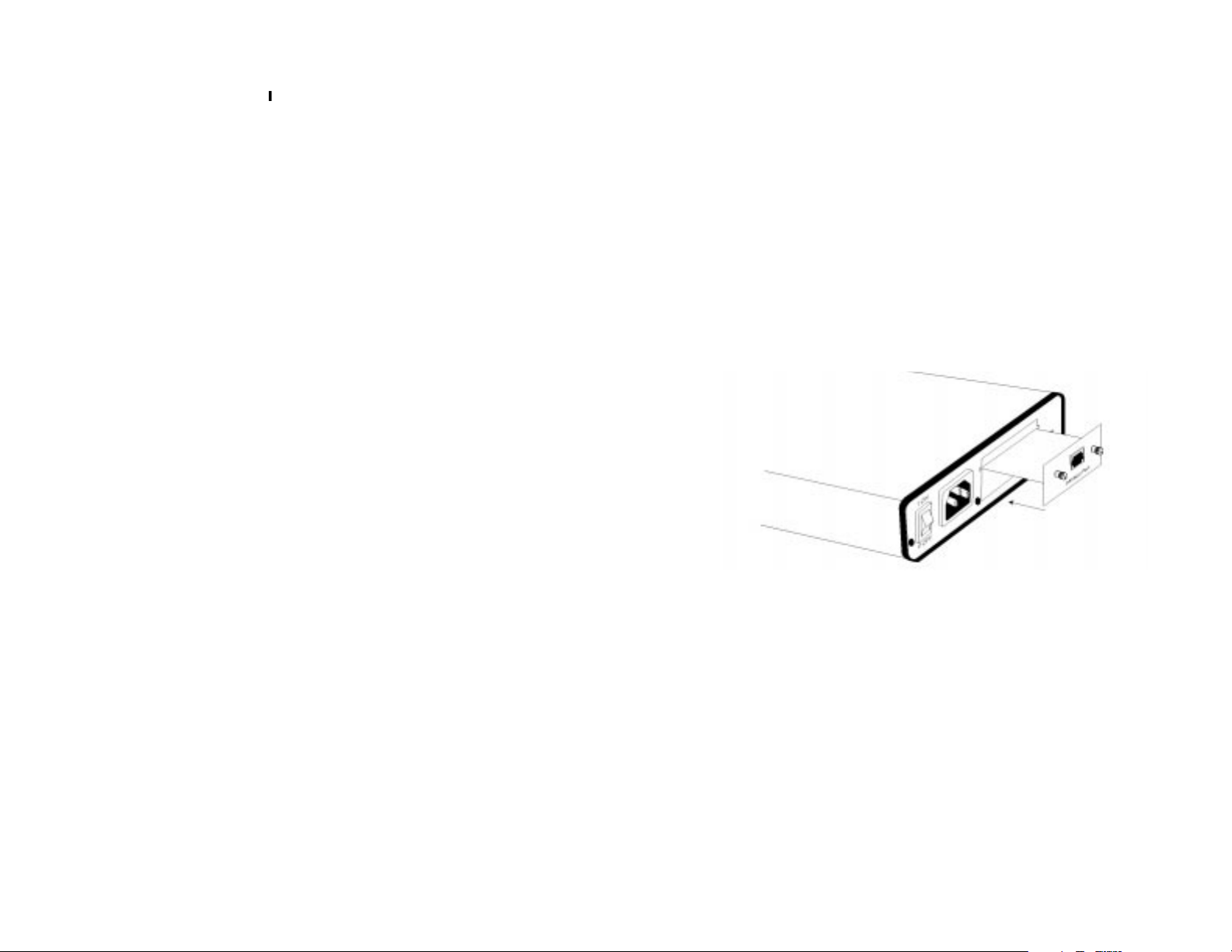
3) While keeping the module’s faceplate parallel with the base unit
rear panel, slide the module straight in–so that the card edge
contacts line up with the socket inside the chassis. Figure 3
(below) shows how a
QuikConnect™
Module plugs into the rear
of the base unit.
NOTE: The card edge connector should meet the socket when
it is almost all the way into the chassis. If you encounter a lot of
resistance, remove the module and repeat steps 2 & 3.
4) With the card edge contacts aligned with the socket, firmly seat
the module by using your thumbs to apply pressure directly to
the right and left edges of the module faceplate. Applying
moderate and
even
pressure should be sufficient to seat the
module. You should hear it “click” into place.
5) To secure the module in place, push the thumbscrews into the
chassis and turn the screws clockwise to tighten.
8
Figure 3. Installating the Model IM 1/J Plug-in Serial Interface Module
Page 6

4.2 CONNECTING TO THE VOICE PORTS
Both voice ports utilize a Data Access Arrangement (DAA) to
interface with telephone equipment. Both ports also utilize an ADPCM
CODEC to convert voice to digital information. The voice ports (V1 and
V2) use integral RJ-11 connectors. The FXS and FXO ports look the
same on the back of the VDQM
QuikConnect™
Module. Each is
shown on the rear of the VDQM module (See Figure 4, below).
Voice Port 1: Port 1 is permanently defined as a 32Kbs channel
conforming to G.721, capable of supporting normal
speech and Fax transmissions up to 14.4Kbs.
Voice Port 2: Port 2 is permanently defined as a 24Kbs channel
conforming to G.723, intended for voice transmission
only.
4.2.1 Identifying FXS/FXO Voice Modules
The VDQM is factory defined as a FXO (Foreign Exchange Service)
or FXO (Foreign Exchange Office) on both voice ports at the factory. To
determine the factory configuration of your VDQM, look at the label on
the inside of the rear panel. You will see one of the following Model
number codes, plus a serial number.
Model IM1/JS - FXS Voice Ports
Model IM1/JO - FXO Voice Ports
9
Figure 4. VDM Rear Panel
Voice Port 1
Voice Port 2
4.2.2 Connecting to an FXS Voice Port (Model IM1/JS)
The FXS (looks like central office) ports are designed as a loop
start telephone interfaces. Each is designed to connect to a telephone
or fax machine using a two-wire interface (as shown below).
VDQM Telephone/Fax
RJ-11 Pin No. RJ-11 Pin No.
3 (TIP) 3 (TIP)
4 (RING) 4 (RING)
4.2.3 Connecting to an FXO Voice Port (Model IM1/JO)
The FXO (looks like telephone) ports are designed as loop start
telephone interfaces. Each is designed to connect to a PBX using a
two-wire interface (as shown below).
VDQM PBX
RJ-11 Pin No. RJ-11 Pin No.
3 (TX+) 3 (TX+)
4 (TX-) 4 (TX-)
10
Warning! Connecting the FXS port of the VDM
to a telephone line WILL damage the VDM and
possibly the telephone line. ONLY connect
telephones or fax machines (or similar
equipment) to the FXS port.
NOTE! The FXO ports are designed to be
connected to a PBX (or similar equipment). If
you wish to connect the FXS ports directly to
PSTN, you MUST obtain approval from the PTT.
Page 7

4.3 CONNECTING TO THE DATA PORT
The VDQM universal interface data interface is configured as DCE
(Data Circuit-Terminating Equipment). It may be configured to
transmit/recieve V.35, EIA-232 or EIA-422 electrical signals by
appropriately setting switches S1 and S2 (See Section 3.2).
As a DCE, the High Density 26 pin data port is designed to connect
directly to DTE (Data Termination Equipment), such as a router. Refer
to the pin assignments in Appendix C to construct a cable to connect
your DTE or DCE equipment. You may also purchase a connecting
cable directly from cable from Patton Electronics.
4.4 CONNECTING TO AC OR DC POWER
Instructions for connecting the power supply Universal Interface
AC Power Supply and DC Power Supply option) are contained within
the base unit user manual. Please refer to the base unit manual for
connection details.
11
12
5.0 OPERATION
Once the VDQM is installed, it should operate transparently. This
sections describes FXS and FXO power-up, and general operating
instructions.
5.1 GENERAL OPERATING INSTRUCTIONS
Both voice ports utilize a Data Access Arrangement (DAA) to
interface with the telephone line. Both ports also utilize an ADPCM
CODEC to convert the voice to digital information.
The FXS configuration (Model IM1/JS) has the capability to
generate battery voltage and ring signal. The battery voltage in the
"On-Hook" condition will be 47 V +/- 10%. In the "Off-Hook condition
the circuit will supply the required current which meets the country of
installation's V/I curve in accordance with NET- 4.
The ring signal has the capability to drive a 1 REN load. This
capability will typically allow for one phone and an extension to be
connected on a single port or to a single phone with a line length up to
1700 feet since most phones have a REN less than 1. This will allow
the unit to be placed in a phone closet if desired, as opposed to sitting
on a desk.
Dialing from an FXS port to an FXO port is accomplished via the
voice channel. DTMF digits generated by the phone connected to an
FXS port are transmitted to the FXO port. Dial Pulse dialing is not
permitted. Dialing between two FXS ports is not required.
Page 8
5.2 OPERATING THE SYNCHRONOUS DATA PORT
The synchronous data port is a variable rate Universal DCE port.
Since both voice ports and framing/signaling information require 64Kbs,
the remaining bandwidth is used for the data port.
The physical interface of the Data Port is a female, High Density
DB-26. The electrical interface is user configured as a V.35, EIA-232,
or EIA-422. The configuration is accomplished via dip switches on the
module. At present, the design uses a "gapped" clock approach. The
clock sent from the module to the DTE terminal is halted during voice
and framing transmission. With the gapped clock approach, the clock
period of the host module is the period of the DCE clock. The effective
data rate at the DCE port is the host data rate minus 64Kbs.
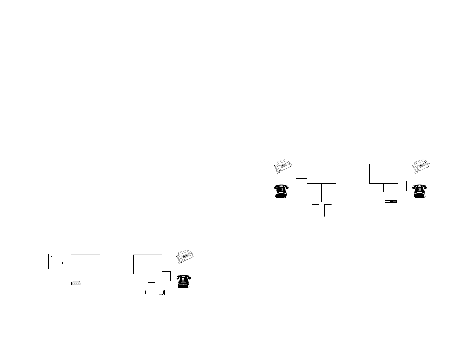
5.3 FXS to FXO APPLICATIONS:
Figure 5 depicts a typical FXO to FXS application. A Model 1092
with an FXS VDQM acts as an extension of two PSTN phone lines,
which is connected to the 1092 with an FXO VDQM. In this example,
calls dialed into 555-1111 will automatically be sent to the fax machine
connected to Port 1 of Unit 2. When the handset of the phone
connected to Port 2 of Unit 2 is lifted, the phone line of Port 2 Unit 1 will
go off hook, passing dial tone and allowing for DTMF dialing. A router
connected to the Data port of Unit 2 can control the modem connected
to the data port of Unit 1.
13
1092 e/w FXO port 1092 e/w FXS port
Public Switch
Port 1
Port 2
DCE
DCE
Port 1
Port 2
2 Wire
FAX
555-1111
555-2222
UNIT 1 UNIT 2
Modem
555-3333
Router
Figure 5. Typical FXS to FXO Application
14
5.4 FXS to FXS APPLICATIONS:
Figure 6 depicts a typical FXS to FXS application. The fax
machine connected to Port 1 on Unit 1 will communicate with the FAX
machine connected to Port 1, Unit 2. Phone numbers are not required
for the FXS modules but may be required for the fax machine to
operate properly. If a fax is to be sent from Unit 1 to Unit 2, a 'dummy'
digit can be entered into FAX 1 (NOTE: the fax machines must be set
to ignore dial tone). When the FAX 1 is given the send command, Port
1 unit 1 will go off-hook. The IM1/J will then send signaling bits to Unit
2, instructing Unit 2 Port 1 to ring. Fax 2 will answer the ring and
normal Fax traffic will commence.
To initiate a voice call, either phone is picked up, the phone at the
far end will ring. Once the phone at the far end is answered, both units
will go into voice mode and a conversation can be held.
1092 e/w FXO port 1092 e/w FXS port
Port 1
Port 2
DCE
DCE
Port 1
Port 2
2 Wire
FAX
Mainframe
FAX
Unit 1
Unit 2
Bridge
Figure 6. Typical FXS to FXO Application
Page 9

AAPPPPEENNDDIIXX AA
PATTON ELECTRONICS MODEL IM1/J
SPECIFICATIONS
Description Extended ( 0.5") "Quick Connect" module
capable of providing a synchronous
universal DCE data port and two loop start
voice ports, either FXS or FXO.
Host Patton Models 1090, 1092, 1092A, 1093,
1094, and 1095.
Signaling In-Band proprietary coding across the host
digital link.
Data Format Synchronous
Data Rate 64, 192, 320, 448, 704, kbps utilizing a
'gapped' clock approach.
Indicators None
Clocking Options Internal
Diagnostics: None
DTE Interface: EIA-232, EIA-422 or ITU V.35
Connection: DCE port: HDDB 26 female
2 Voice ports: RJ-11.
Isolation Voice ports: 1500 VRMS, FCC Part 68
Surge Protection: Voice Ports: Tip & Ring protected by 320 V
sidactor.
Power Requirements: +5V @ 1 Amp
Compliance: EN 55022(CE), EN 60950, FCC Part15
Class A,
Control: Dipswitch Setup
15
APPENDIX B
PATTON ELECTRONICS MODEL IM1/J
FACTORY REPLACEMENT PARTS
AND ACCESSORIES
P
atton Electronics Model # Description
IM1/A...............................V.24 with DB25F
IM1/B...............................RS422/RS530 with DB25F
IM1/C...............................V.35 with M34F
IM1/D...............................X.21 with DB15F
IM1/E...............................V.35 with DB25F
IM1/F...............................G.703 with RJ45
IM1/I ................................Ethernet Bridge Module
IM1/J................................Voice/Data Module
0805US ...........................American Power Cord
0805EUR.........................European Power Cord CEE 7
0805UK ...........................United Kingdom Power Cord
0805AUS.........................Australia/New Zealand Power Cord
0805DEN.........................Denmark Power Cord
0805FR............................France/Belgium Power Cord
0805IN.............................India Power Cord
0805IS.............................Israel Power Cord
0805JAP..........................Japan Power Cord
0805SW...........................Switzerland Power Cord
07M1090SVC..................1090 Series Service Manual
16
Page 10
AAPPPPEENNDDIIXX CC
PATTON ELECTRONICS MODEL IM1/J
INTERFACE PIN ASSIGNMENT
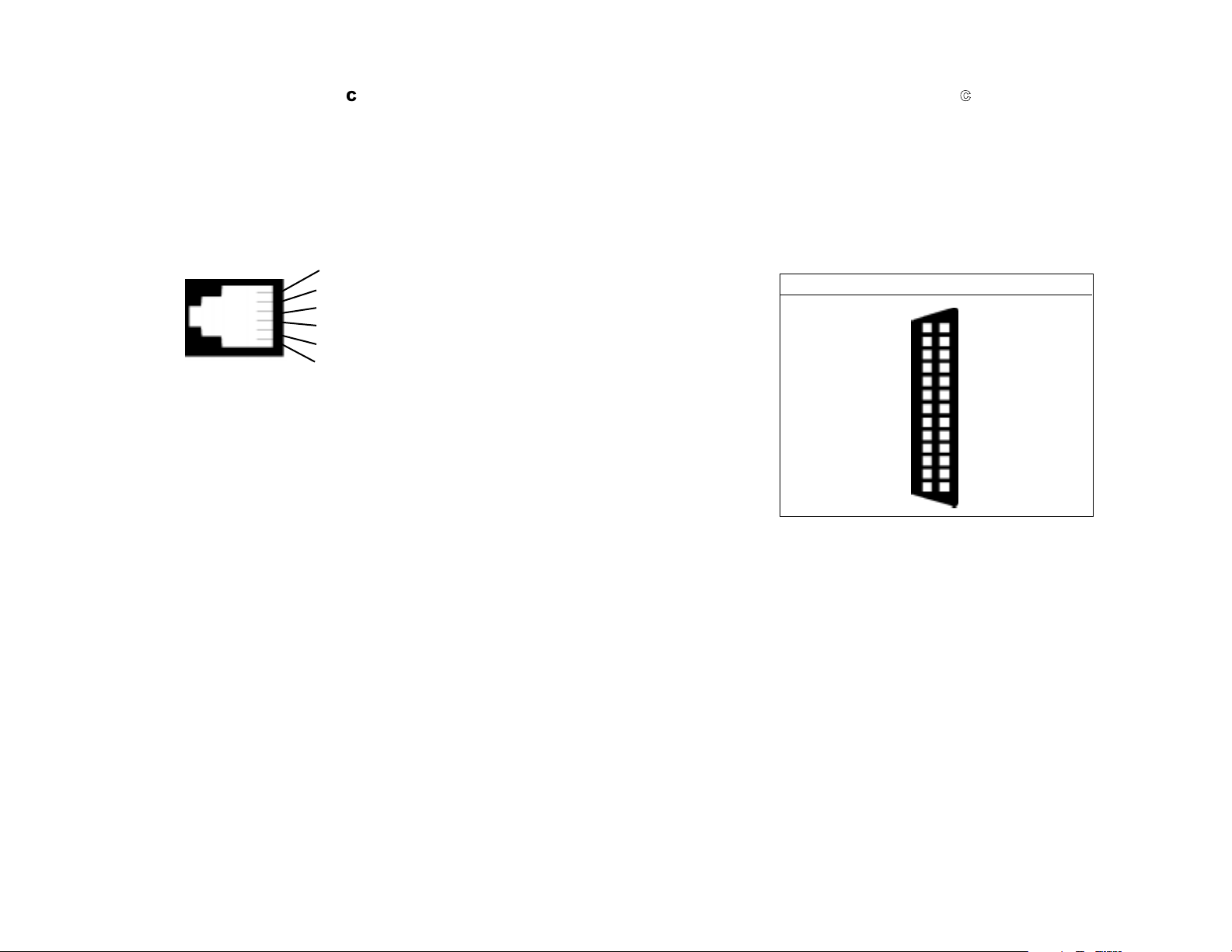
V1 & V2 Voice Ports
(RJ-11 Female Connector)
1 (no connection)
2 (no connection)
3 TIP
4 RING
5 (no connection)
6 (no connection)
17
AAPPPPEENNDDIIXX CC
PATTON ELECTRONICS MODEL IM1/J
INTERFACE PIN ASSIGNMENT
EIA-232, EIA-422 Interface Pin Description
(UD-26 Female Connector)
(DCE Configuration)
© Copyright 1998
Patton Electronics Company
All Rights Reserved
13- (CTS/) Clear to Send
12- (TC/) Transmit Clock
11- (XTC/) Network Clock
10- (CD/) Carrier Detect
9- (RC/) Receive Clock
8- (CD) Carrier Detect
7- (SG) Signal Ground
6- (DSR) Data Set Ready
5- (CTS) Clear to Send
4- (RTS) Request to Send
3- (RD) Receive Data
2- (TD) Transmit Data
1- (FG) Frame Ground
UNIVERSAL D-26 INTERFACE (DCE CONFIGURATION)
Not Used -26
Not Used -25
Network Clock (XTC) -24
Data Term Ready (DTR/) -23
Data Set Ready (DSR/) -22
Not Used -21
Data Term Ready (DTR) -20
Request to Send (RTS/) -19
Not Used -18
Receive Clock (RC) -17
Receive Data (RD/) -16
Transmit Clock (TC) -15
Transmit Data (TD/) -14
18
 Loading...