

Page 1

For Quick
Start Installation
ForeSight 6300
Network Management System
Getting Started Guide
Sales Office: +1 (301) 975-1000
Technical Support: +1 (301) 975-1007
E-mail: support@patton.com
WWW: www.patton.com
Document Number: 09203U1-001 Rev. A
Part Number: 07MFS6300-GS
Revised: April 18, 2008
Page 2

Patton Electronics Company, Inc.
7622 Rickenbacker Drive
Gaithersburg, MD 20879 USA
Tel: +1 (301) 975-1000
Fax: +1 (301) 869-9293
Support: +1 (301) 975-1007
Web: www.patton.com
E-mail: support@patton.com
Trademark Statement
The term ForeSight is a trademark of Patton Electronics Company. All other trademarks presented in this document are the property of their respective owners.
Copyright © 2008, Patton Electronics Company. All rights reserved.
The information in this document is subject to change without notice. Patton Electronics assumes no liability for errors that may appear in this document.
Warranty Information
The software described in this document is furnished under a license and may be used
or copied only in accordance with the terms of such license. For information about the
license, go to www.patton.com .
Patton Electronics warrants all NMS components to be free from defects, and will—at
our option—repair or replace the product should it fail within one year from the first
date of the shipment.
This warranty is limited to defects in workmanship or materials, and does not cover
customer damage, abuse or unauthorized modification. If the product fails to perform
as warranted, your sole recourse shall be repair or replacement as described above.
Under no condition shall Patton Electronics be liable for any damages incurred by the
use of this product. These damages include, but are not limited to, the following: lost
profits, lost savings and incidental or consequential damages arising from the use of or
inability to use this product. Patton Electronics specifically disclaims all other warranties, expressed or implied, and the installation or use of this product shall be deemed
an acceptance of these terms by the user.
Page 3

Summary Table of Contents
1 Introduction.................................................................................................................................................. 14
2 Discovering Your Network............................................................................................................................ 21
3 Configuring Alarms and Clocking ................................................................................................................ 28
4 Configuring and Managing Devices.............................................................................................................. 37
5 Configuring the 2616RC Card...................................................................................................................... 43
6 Configuring the 3096RC Card...................................................................................................................... 56
7 Configuring the 6511RC Card...................................................................................................................... 76
8 Configuring Chassis ...................................................................................................................................... 91
9 Monitoring Managed Objects ....................................................................................................................... 97
10 Managing Network Events .......................................................................................................................... 103
11 Monitoring Performance Data .................................................................................................................... 109
12 Contacting Patton for assistance ................................................................................................................. 115
3
Page 4

Table of Contents
Summary Table of Contents ........................................................................................................................... 3
Table of Contents ........................................................................................................................................... 4
List of Figures ............................................................................................................................................... 10
List of Tables ................................................................................................................................................ 12
About this guide ........................................................................................................................................... 13
Audience............................................................................................................................................................... 13
Structure............................................................................................................................................................... 13
1 Introduction.................................................................................................................................................. 14
Overview ...............................................................................................................................................................15
FS6300 NMS Features ..........................................................................................................................................15
Common User Tasks.............................................................................................................................................15
Bringing up the NMS Server from Linux ..............................................................................................................16
Bringing up the NMS Application Client from Windows XP................................................................................16
Logging into the Application Client ......................................................................................................................16
Configuring Your Password ............................................................................................................................17
Configuring your password before connecting to the client .......................................................................17
Configuring your password from the client ...............................................................................................17
Troubleshooting .............................................................................................................................................18
Using the NMS Menus and Toolbars....................................................................................................................20
Logging out of the Application Client ...................................................................................................................20
2 Discovering Your Network............................................................................................................................ 21
Introduction..........................................................................................................................................................22
Starting the Discovery Process ...............................................................................................................................22
Viewing Node Information After Discovery ..........................................................................................................24
Configuring Multiple Cards ..................................................................................................................................24
Updating the Configuration ............................................................................................................................24
Saving the Configuration ................................................................................................................................26
Forcing Discovery for Selected Cards ..............................................................................................................26
Re-Discovering Cards............................................................................................................................................27
3 Configuring Alarms and Clocking ................................................................................................................ 28
Introduction..........................................................................................................................................................29
Configuring the Alarm Trap Manager ...................................................................................................................29
Configuring Alarms through the Network Node .............................................................................................29
Configuring Alarms through a Card in the Chassis .........................................................................................30
Alarm Indications ...........................................................................................................................................32
Viewing a Summary of Alarms ..............................................................................................................................32
Configuring Clocking Synchronization .................................................................................................................33
Refreshing the alarms after configuring clocking .............................................................................................34
Configuring Card System Clocking.......................................................................................................................34
4
Page 5

5
FS6300 NMS Getting Started Guide
Table of Contents
4 Configuring and Managing Devices.............................................................................................................. 37
Introduction..........................................................................................................................................................38
Adding Devices .....................................................................................................................................................38
Working with Network Maps................................................................................................................................39
Geographical Areas .........................................................................................................................................39
Nodes .............................................................................................................................................................39
Chassis ............................................................................................................................................................39
Slots/Devices ...................................................................................................................................................39
Ports/Interfaces ...............................................................................................................................................39
Managing Operator Actions ..................................................................................................................................40
Record the current configuration ....................................................................................................................40
Reboot the device ............................................................................................................................................40
Set the factory default configuration ...............................................................................................................41
Configuring Cards.................................................................................................................................................42
Viewing LEDs ................................................................................................................................................42
5 Configuring the 2616RC Card...................................................................................................................... 43
Introduction..........................................................................................................................................................44
2616RC Configuration Menu ...............................................................................................................................44
Viewing the Front Panel........................................................................................................................................45
Configuring the Card System ................................................................................................................................45
Modify System Parameters ..............................................................................................................................45
View System Status .........................................................................................................................................46
View System Status Details .............................................................................................................................46
View Ethernet Status .......................................................................................................................................46
View SNMP/HTTP Parameters .....................................................................................................................46
Configuring Ethernet Settings ...............................................................................................................................47
Modify Ethernet Parameters ...........................................................................................................................47
View Ethernet Statistics ..................................................................................................................................47
Viewing Events and Alerts .....................................................................................................................................48
Exporting/Importing the Configuration ................................................................................................................48
Exporting the Configuration ...........................................................................................................................48
Importing the Configuration ..........................................................................................................................49
Configuring IP Routing.........................................................................................................................................50
Add Route ......................................................................................................................................................50
Viewing the System Log ........................................................................................................................................51
Modify Syslog Configuration ..........................................................................................................................51
Change Alarm Status ......................................................................................................................................51
Configuring the T1/E1 Ports.................................................................................................................................52
View Configuration ........................................................................................................................................52
Modify Line Interface Settings ........................................................................................................................52
Modify Test Settings .......................................................................................................................................53
Set Channel Assignments ................................................................................................................................54
View Line Status .............................................................................................................................................54
Page 6

6
FS6300 NMS Getting Started Guide
Table of Contents
Viewing T1/E1 Reports.........................................................................................................................................55
Viewing the T1/E1 Map Layer ..............................................................................................................................55
6 Configuring the 3096RC Card...................................................................................................................... 56
Introduction..........................................................................................................................................................57
3096RC Configuration Menu ...............................................................................................................................57
Viewing the Front Panel........................................................................................................................................58
Configuring the Card System ................................................................................................................................58
Modify System Parameters ..............................................................................................................................58
View System Status .........................................................................................................................................59
View System Status Details .............................................................................................................................59
View Ethernet Status .......................................................................................................................................59
View SNMP/HTTP Parameters .....................................................................................................................59
Configuring Ethernet Settings ...............................................................................................................................60
Modify Ethernet Parameters ...........................................................................................................................60
View Ethernet Statistics ..................................................................................................................................60
Viewing Events and Alerts .....................................................................................................................................61
Exporting/Importing the Configuration ................................................................................................................61
Exporting the Configuration ...........................................................................................................................61
Importing the Configuration ..........................................................................................................................62
Configuring G.SHDSL Ports ................................................................................................................................63
Activating/Deactivating All Ports ....................................................................................................................63
Configuring Individual Ports ..........................................................................................................................64
View Port Information ..............................................................................................................................64
Edit CO/CPE Options ..............................................................................................................................65
Determine Best Payload Rate ....................................................................................................................66
Viewing G.SHDSL Reports...................................................................................................................................67
Configuring IP Routing.........................................................................................................................................68
Add Route ......................................................................................................................................................68
Viewing the System Log ........................................................................................................................................69
Modify Syslog Configuration ..........................................................................................................................69
Change Alarm Status ......................................................................................................................................69
Configuring the T1/E1 Ports.................................................................................................................................70
View Configuration ........................................................................................................................................70
Modify Line Interface Settings ........................................................................................................................70
Modify Test Settings .......................................................................................................................................71
Set Channel Assignments ................................................................................................................................72
View Line Status .............................................................................................................................................72
Managing Inband T1/E1 Channels .......................................................................................................................73
Adding a T1/E1 Management Channel ..........................................................................................................73
Viewing T1/E1 Reports.........................................................................................................................................74
Viewing the T1/E1 Map Layer ..............................................................................................................................75
Viewing the G.SHDSL Map Layer........................................................................................................................75
7 Configuring the 6511RC Card...................................................................................................................... 76
Page 7

7
FS6300 NMS Getting Started Guide
Table of Contents
Introduction..........................................................................................................................................................77
6511RC Configuration Menu ...............................................................................................................................77
Viewing the Front Panel........................................................................................................................................78
Configuring the Card System ................................................................................................................................78
Modify System Parameters ..............................................................................................................................78
View System Status .........................................................................................................................................79
View System Status Details .............................................................................................................................79
View Ethernet Status .......................................................................................................................................79
View SNMP/HTTP Parameters .....................................................................................................................80
Configuring Ethernet Settings ...............................................................................................................................80
Modify Ethernet Parameters ...........................................................................................................................80
View Ethernet Statistics ..................................................................................................................................80
Configuring E1 Links............................................................................................................................................81
Edit Line Interface Settings .............................................................................................................................81
View Alarm Status ..........................................................................................................................................81
View Line Statistics .........................................................................................................................................81
Configure DS0 Settings ..................................................................................................................................81
Enable/Disable DS0 Numbers ..................................................................................................................81
Edit Test Settings ............................................................................................................................................82
Configuring IP Routing.........................................................................................................................................84
Add Route ......................................................................................................................................................84
Viewing Events and Alerts .....................................................................................................................................85
Exporting/Importing the Configuration ................................................................................................................85
Exporting the Configuration ...........................................................................................................................85
Importing the Configuration ..........................................................................................................................86
Viewing the System Log ........................................................................................................................................87
Modify Syslog Configuration ..........................................................................................................................87
Configuring SDH..................................................................................................................................................88
Configuring SDH Interfaces ...........................................................................................................................88
Configuring SDH Paths ..................................................................................................................................89
Configuring SDH Mapper ..............................................................................................................................90
Viewing Alarm Status ......................................................................................................................................90
Viewing Statistics ............................................................................................................................................90
Viewing E1Link Layers..........................................................................................................................................90
8 Configuring Chassis ...................................................................................................................................... 91
Introduction..........................................................................................................................................................92
Chassis Configuration Menu .................................................................................................................................92
Viewing the Chassis LEDs.....................................................................................................................................93
Managing Inband H110 Channels ........................................................................................................................93
Add H110 Management Channel ...................................................................................................................94
Delete H110 Management Channel ...............................................................................................................95
Viewing the Card Layer Map.................................................................................................................................96
9 Monitoring Managed Objects ....................................................................................................................... 97
Page 8

8
FS6300 NMS Getting Started Guide
Table of Contents
Introduction..........................................................................................................................................................98
Working with Managed Objects............................................................................................................................98
Geographical Areas .........................................................................................................................................99
Network Nodes ...............................................................................................................................................99
Chassis ............................................................................................................................................................99
Network Addresses ........................................................................................................................................100
Cards ............................................................................................................................................................100
Interfaces ......................................................................................................................................................100
DSL Ports .....................................................................................................................................................101
IDSL Ports ....................................................................................................................................................101
T1/E1 Ports ..................................................................................................................................................101
E1 Links .......................................................................................................................................................101
Working with Unmanaged Objects .....................................................................................................................102
Managing an Unmanaged Object .................................................................................................................102
10 Managing Network Events .......................................................................................................................... 103
Introduction........................................................................................................................................................104
Viewing Network Events.....................................................................................................................................104
Viewing the current list of events ..................................................................................................................104
Viewing details of an event ............................................................................................................................105
Viewing alarms related to an event ................................................................................................................105
Searching Network Events...................................................................................................................................106
Saving Network Events........................................................................................................................................106
Saving Events to File .....................................................................................................................................106
Exporting Events ...........................................................................................................................................107
Printing Events .............................................................................................................................................107
About Trap Parsers..............................................................................................................................................108
About Event Parsers.............................................................................................................................................108
About Event Filters..............................................................................................................................................108
11 Monitoring Performance Data .................................................................................................................... 109
Introduction........................................................................................................................................................110
Viewing Configured Collection Data ..................................................................................................................110
Viewing Current Performance Data ....................................................................................................................111
Viewing Collected Performance Data ..................................................................................................................113
12 Contacting Patton for assistance ................................................................................................................. 115
Introduction........................................................................................................................................................116
Contact information............................................................................................................................................116
Patton support headquarters in the USA .......................................................................................................116
Alternate Patton support for Europe, Middle East, and Africa (EMEA) ........................................................116
Warranty Service and Returned Merchandise Authorizations (RMAs).................................................................116
Warranty coverage ........................................................................................................................................116
Out-of-warranty service ...........................................................................................................................117
Returns for credit ....................................................................................................................................117
Return for credit policy ...........................................................................................................................117
Page 9

9
FS6300 NMS Getting Started Guide
RMA numbers ..............................................................................................................................................117
Shipping instructions ..............................................................................................................................117
Table of Contents
Page 10

List of Figures
1 Logging in to the application client . . . . . . . . . . . . . . . . . . . . . . . . . . . . . . . . . . . . . . . . . . . . . . . . . . . . . . . . . . 16
2 Tools > Discovery Administration . . . . . . . . . . . . . . . . . . . . . . . . . . . . . . . . . . . . . . . . . . . . . . . . . . . . . . . . . . 22
3 Discovery Window . . . . . . . . . . . . . . . . . . . . . . . . . . . . . . . . . . . . . . . . . . . . . . . . . . . . . . . . . . . . . . . . . . . . . . 22
4 Network Discovery tab . . . . . . . . . . . . . . . . . . . . . . . . . . . . . . . . . . . . . . . . . . . . . . . . . . . . . . . . . . . . . . . . . . . 23
5 Tools > Multiple Card Configuration . . . . . . . . . . . . . . . . . . . . . . . . . . . . . . . . . . . . . . . . . . . . . . . . . . . . . . . . 24
6 Multiple Card Configuration > Card Parameters . . . . . . . . . . . . . . . . . . . . . . . . . . . . . . . . . . . . . . . . . . . . . . . 25
7 Multiple Card Configuration > Record Current Configuration . . . . . . . . . . . . . . . . . . . . . . . . . . . . . . . . . . . . 26
8 Re-Discover Cards . . . . . . . . . . . . . . . . . . . . . . . . . . . . . . . . . . . . . . . . . . . . . . . . . . . . . . . . . . . . . . . . . . . . . . 27
9 Alarm Trap Manager . . . . . . . . . . . . . . . . . . . . . . . . . . . . . . . . . . . . . . . . . . . . . . . . . . . . . . . . . . . . . . . . . . . . 29
10 View Alarm Details . . . . . . . . . . . . . . . . . . . . . . . . . . . . . . . . . . . . . . . . . . . . . . . . . . . . . . . . . . . . . . . . . . . . . . 30
11 Modify Alarm Details . . . . . . . . . . . . . . . . . . . . . . . . . . . . . . . . . . . . . . . . . . . . . . . . . . . . . . . . . . . . . . . . . . . . 31
12 Alarm Summary View options (Tabular, Graphical, and Pie Chart) . . . . . . . . . . . . . . . . . . . . . . . . . . . . . . . . . 32
13 Chassis Menu > Chassis Clocking Sync . . . . . . . . . . . . . . . . . . . . . . . . . . . . . . . . . . . . . . . . . . . . . . . . . . . . . . 33
14 Modify System Clocking . . . . . . . . . . . . . . . . . . . . . . . . . . . . . . . . . . . . . . . . . . . . . . . . . . . . . . . . . . . . . . . . . 33
15 Card Menu > Card System Clocking . . . . . . . . . . . . . . . . . . . . . . . . . . . . . . . . . . . . . . . . . . . . . . . . . . . . . . . . 34
16 View System Clocking . . . . . . . . . . . . . . . . . . . . . . . . . . . . . . . . . . . . . . . . . . . . . . . . . . . . . . . . . . . . . . . . . . . 35
17 Modify System Clocking . . . . . . . . . . . . . . . . . . . . . . . . . . . . . . . . . . . . . . . . . . . . . . . . . . . . . . . . . . . . . . . . . 35
18 Add SNMP Device window . . . . . . . . . . . . . . . . . . . . . . . . . . . . . . . . . . . . . . . . . . . . . . . . . . . . . . . . . . . . . . . 38
19 Network Maps . . . . . . . . . . . . . . . . . . . . . . . . . . . . . . . . . . . . . . . . . . . . . . . . . . . . . . . . . . . . . . . . . . . . . . . . . 39
20 Operator Actions > Reset Options window . . . . . . . . . . . . . . . . . . . . . . . . . . . . . . . . . . . . . . . . . . . . . . . . . . . . 40
21 Record Current Configuration . . . . . . . . . . . . . . . . . . . . . . . . . . . . . . . . . . . . . . . . . . . . . . . . . . . . . . . . . . . . . 40
22 Hard Reset . . . . . . . . . . . . . . . . . . . . . . . . . . . . . . . . . . . . . . . . . . . . . . . . . . . . . . . . . . . . . . . . . . . . . . . . . . . . 41
23 Set Factory Default Configuration . . . . . . . . . . . . . . . . . . . . . . . . . . . . . . . . . . . . . . . . . . . . . . . . . . . . . . . . . . 41
24 2616RC Configuration Menu . . . . . . . . . . . . . . . . . . . . . . . . . . . . . . . . . . . . . . . . . . . . . . . . . . . . . . . . . . . . . 44
25 2616RC Front Panel LEDs . . . . . . . . . . . . . . . . . . . . . . . . . . . . . . . . . . . . . . . . . . . . . . . . . . . . . . . . . . . . . . . . 45
26 Modify 2616RC Card System Parameters . . . . . . . . . . . . . . . . . . . . . . . . . . . . . . . . . . . . . . . . . . . . . . . . . . . . . 46
27 Modify 2616RC Ethernet Parameters . . . . . . . . . . . . . . . . . . . . . . . . . . . . . . . . . . . . . . . . . . . . . . . . . . . . . . . . 47
28 2616RC Events and Alerts . . . . . . . . . . . . . . . . . . . . . . . . . . . . . . . . . . . . . . . . . . . . . . . . . . . . . . . . . . . . . . . . 48
29 Export Configuration . . . . . . . . . . . . . . . . . . . . . . . . . . . . . . . . . . . . . . . . . . . . . . . . . . . . . . . . . . . . . . . . . . . . 48
30 Import Configuration . . . . . . . . . . . . . . . . . . . . . . . . . . . . . . . . . . . . . . . . . . . . . . . . . . . . . . . . . . . . . . . . . . . . 49
31 Add a New Route to 2616RC . . . . . . . . . . . . . . . . . . . . . . . . . . . . . . . . . . . . . . . . . . . . . . . . . . . . . . . . . . . . . . 50
32 Modify System Log . . . . . . . . . . . . . . . . . . . . . . . . . . . . . . . . . . . . . . . . . . . . . . . . . . . . . . . . . . . . . . . . . . . . . . 51
33 Set System Card Alarm Status . . . . . . . . . . . . . . . . . . . . . . . . . . . . . . . . . . . . . . . . . . . . . . . . . . . . . . . . . . . . . . 51
34 2616RC T1/E1 Link Configuration window . . . . . . . . . . . . . . . . . . . . . . . . . . . . . . . . . . . . . . . . . . . . . . . . . . 52
35 2616RC T1/E1 Test Settings . . . . . . . . . . . . . . . . . . . . . . . . . . . . . . . . . . . . . . . . . . . . . . . . . . . . . . . . . . . . . . 53
36 2616RC T1/E1 Channel Assignment . . . . . . . . . . . . . . . . . . . . . . . . . . . . . . . . . . . . . . . . . . . . . . . . . . . . . . . . 54
37 2616RC T1/E1 Reports . . . . . . . . . . . . . . . . . . . . . . . . . . . . . . . . . . . . . . . . . . . . . . . . . . . . . . . . . . . . . . . . . . 55
38 2616RC T1/E1 Port Map . . . . . . . . . . . . . . . . . . . . . . . . . . . . . . . . . . . . . . . . . . . . . . . . . . . . . . . . . . . . . . . . 55
39 3096RC Configuration Menu . . . . . . . . . . . . . . . . . . . . . . . . . . . . . . . . . . . . . . . . . . . . . . . . . . . . . . . . . . . . . 57
40 3096RC Front Panel LEDs . . . . . . . . . . . . . . . . . . . . . . . . . . . . . . . . . . . . . . . . . . . . . . . . . . . . . . . . . . . . . . . . 58
41 Modify 3096RC Card System Parameters . . . . . . . . . . . . . . . . . . . . . . . . . . . . . . . . . . . . . . . . . . . . . . . . . . . . . 59
42 Modify 3096RC Ethernet Parameters . . . . . . . . . . . . . . . . . . . . . . . . . . . . . . . . . . . . . . . . . . . . . . . . . . . . . . . . 60
43 3096C Events and Alerts . . . . . . . . . . . . . . . . . . . . . . . . . . . . . . . . . . . . . . . . . . . . . . . . . . . . . . . . . . . . . . . . . 61
44 Export Configuration . . . . . . . . . . . . . . . . . . . . . . . . . . . . . . . . . . . . . . . . . . . . . . . . . . . . . . . . . . . . . . . . . . . . 61
45 Import Configuration . . . . . . . . . . . . . . . . . . . . . . . . . . . . . . . . . . . . . . . . . . . . . . . . . . . . . . . . . . . . . . . . . . . . 62
46 3096RC G.SHDSL window . . . . . . . . . . . . . . . . . . . . . . . . . . . . . . . . . . . . . . . . . . . . . . . . . . . . . . . . . . . . . . . 63
47 3096RC Edit G.SHDSL Configuration . . . . . . . . . . . . . . . . . . . . . . . . . . . . . . . . . . . . . . . . . . . . . . . . . . . . . . 64
10
Page 11

11
FS6300 NMS Getting Started Guide
48 3096RC Edit CO Options . . . . . . . . . . . . . . . . . . . . . . . . . . . . . . . . . . . . . . . . . . . . . . . . . . . . . . . . . . . . . . . . 65
49 3096RC Line Provision Tool . . . . . . . . . . . . . . . . . . . . . . . . . . . . . . . . . . . . . . . . . . . . . . . . . . . . . . . . . . . . . . 66
50 3096RC G.SHDSL Reports . . . . . . . . . . . . . . . . . . . . . . . . . . . . . . . . . . . . . . . . . . . . . . . . . . . . . . . . . . . . . . . 67
51 Add a New Route to 3096RC . . . . . . . . . . . . . . . . . . . . . . . . . . . . . . . . . . . . . . . . . . . . . . . . . . . . . . . . . . . . . . 68
52 Modify System Log . . . . . . . . . . . . . . . . . . . . . . . . . . . . . . . . . . . . . . . . . . . . . . . . . . . . . . . . . . . . . . . . . . . . . . 69
53 Set System Card Alarm Status . . . . . . . . . . . . . . . . . . . . . . . . . . . . . . . . . . . . . . . . . . . . . . . . . . . . . . . . . . . . . . 69
54 3096RC T1/E1 Link Configuration window . . . . . . . . . . . . . . . . . . . . . . . . . . . . . . . . . . . . . . . . . . . . . . . . . . 70
55 3096RC T1/E1 Test Settings . . . . . . . . . . . . . . . . . . . . . . . . . . . . . . . . . . . . . . . . . . . . . . . . . . . . . . . . . . . . . . 71
56 3096RC T1/E1 Channel Assignment . . . . . . . . . . . . . . . . . . . . . . . . . . . . . . . . . . . . . . . . . . . . . . . . . . . . . . . . 72
57 3096RC T1/E1 Inband Management window . . . . . . . . . . . . . . . . . . . . . . . . . . . . . . . . . . . . . . . . . . . . . . . . . 73
58 3096RC T1/E1 Reports . . . . . . . . . . . . . . . . . . . . . . . . . . . . . . . . . . . . . . . . . . . . . . . . . . . . . . . . . . . . . . . . . . 74
59 3096RC T1/E1 Port Map . . . . . . . . . . . . . . . . . . . . . . . . . . . . . . . . . . . . . . . . . . . . . . . . . . . . . . . . . . . . . . . . 75
60 3096RC G.SHDSL Port Map . . . . . . . . . . . . . . . . . . . . . . . . . . . . . . . . . . . . . . . . . . . . . . . . . . . . . . . . . . . . . 75
61 6511RC Configuration Menu . . . . . . . . . . . . . . . . . . . . . . . . . . . . . . . . . . . . . . . . . . . . . . . . . . . . . . . . . . . . . 77
62 6511RC Front Panel LEDs . . . . . . . . . . . . . . . . . . . . . . . . . . . . . . . . . . . . . . . . . . . . . . . . . . . . . . . . . . . . . . . . 78
63 Modify 6511RC Card System Parameters . . . . . . . . . . . . . . . . . . . . . . . . . . . . . . . . . . . . . . . . . . . . . . . . . . . . . 79
64 Modify 6511RC Ethernet Parameters . . . . . . . . . . . . . . . . . . . . . . . . . . . . . . . . . . . . . . . . . . . . . . . . . . . . . . . . 80
65 6511RC DS0 Details . . . . . . . . . . . . . . . . . . . . . . . . . . . . . . . . . . . . . . . . . . . . . . . . . . . . . . . . . . . . . . . . . . . . 82
66 6511RC E1 Link Test Settings . . . . . . . . . . . . . . . . . . . . . . . . . . . . . . . . . . . . . . . . . . . . . . . . . . . . . . . . . . . . . 83
67 Add a New Route to 6511RC . . . . . . . . . . . . . . . . . . . . . . . . . . . . . . . . . . . . . . . . . . . . . . . . . . . . . . . . . . . . . . 84
68 6511RC Events and Alerts . . . . . . . . . . . . . . . . . . . . . . . . . . . . . . . . . . . . . . . . . . . . . . . . . . . . . . . . . . . . . . . . 85
69 Export Configuration . . . . . . . . . . . . . . . . . . . . . . . . . . . . . . . . . . . . . . . . . . . . . . . . . . . . . . . . . . . . . . . . . . . . 85
70 Import Configuration . . . . . . . . . . . . . . . . . . . . . . . . . . . . . . . . . . . . . . . . . . . . . . . . . . . . . . . . . . . . . . . . . . . . 86
71 Modify System Log . . . . . . . . . . . . . . . . . . . . . . . . . . . . . . . . . . . . . . . . . . . . . . . . . . . . . . . . . . . . . . . . . . . . . . 87
72 6511RC SDH Interface Configuration . . . . . . . . . . . . . . . . . . . . . . . . . . . . . . . . . . . . . . . . . . . . . . . . . . . . . . . 88
73 6511RC SDH Path Configuration . . . . . . . . . . . . . . . . . . . . . . . . . . . . . . . . . . . . . . . . . . . . . . . . . . . . . . . . . . 89
74 6511RC E1 Link Map . . . . . . . . . . . . . . . . . . . . . . . . . . . . . . . . . . . . . . . . . . . . . . . . . . . . . . . . . . . . . . . . . . . 90
75 Chassis Configuration Menu . . . . . . . . . . . . . . . . . . . . . . . . . . . . . . . . . . . . . . . . . . . . . . . . . . . . . . . . . . . . . . 92
76 Chassis LEDs . . . . . . . . . . . . . . . . . . . . . . . . . . . . . . . . . . . . . . . . . . . . . . . . . . . . . . . . . . . . . . . . . . . . . . . . . . 93
77 Chassis Defined Channels . . . . . . . . . . . . . . . . . . . . . . . . . . . . . . . . . . . . . . . . . . . . . . . . . . . . . . . . . . . . . . . . . 93
78 Add H110 Management Channel to Chassis . . . . . . . . . . . . . . . . . . . . . . . . . . . . . . . . . . . . . . . . . . . . . . . . . . 94
79 Delete H110 Management Channel from Chassis . . . . . . . . . . . . . . . . . . . . . . . . . . . . . . . . . . . . . . . . . . . . . . 95
80 Chassis Card Layer Map . . . . . . . . . . . . . . . . . . . . . . . . . . . . . . . . . . . . . . . . . . . . . . . . . . . . . . . . . . . . . . . . . . 96
81 Managed Objects Table . . . . . . . . . . . . . . . . . . . . . . . . . . . . . . . . . . . . . . . . . . . . . . . . . . . . . . . . . . . . . . . . . . 98
82 UnManaged Objects Table . . . . . . . . . . . . . . . . . . . . . . . . . . . . . . . . . . . . . . . . . . . . . . . . . . . . . . . . . . . . . . . 102
83 Fault Management > Network Events . . . . . . . . . . . . . . . . . . . . . . . . . . . . . . . . . . . . . . . . . . . . . . . . . . . . . . . 104
84 Performance > Configured Collection . . . . . . . . . . . . . . . . . . . . . . . . . . . . . . . . . . . . . . . . . . . . . . . . . . . . . . . 110
85 Plot Current Statistic . . . . . . . . . . . . . . . . . . . . . . . . . . . . . . . . . . . . . . . . . . . . . . . . . . . . . . . . . . . . . . . . . . . 112
86 Plot Collected Statistic . . . . . . . . . . . . . . . . . . . . . . . . . . . . . . . . . . . . . . . . . . . . . . . . . . . . . . . . . . . . . . . . . . 113
Page 12

List of Tables
1 Troubleshooting messages . . . . . . . . . . . . . . . . . . . . . . . . . . . . . . . . . . . . . . . . . . . . . . . . . . . . . . . . . . . . . . . . . 18
2 Network Event Details . . . . . . . . . . . . . . . . . . . . . . . . . . . . . . . . . . . . . . . . . . . . . . . . . . . . . . . . . . . . . . . . . . 105
3 Configured Collection Properties . . . . . . . . . . . . . . . . . . . . . . . . . . . . . . . . . . . . . . . . . . . . . . . . . . . . . . . . . . 111
12
Page 13

About this guide
The Patton ForeSight 6300 NMS Getting Started Guide helps you to understand and work with the FS6300
Network Management System (NMS). For more detailed information about configuring advanced features,
see the ForeSight 6300 NMS Administrator’s Reference Guide .
Audience
This guide is intended for the following users:
• Operators
• Installers
Structure
This guide contains the following chapters and appendices:
• Chapter 1 on page 14 provides basic information on NMS features and functions
• Chapter 2 on page 21 provides information on discovering your network
• Chapter 3 on page 28 provides information on configuring alarms and clocking
• Chapter 4 on page 37 provides information on configuring and managing individual devices
• Chapter 5 on page 43 provides basic information on configuring the 2616RC card
• Chapter 6 on page 56 provides basic information on configuring the 3096RC card
• Chapter 7 on page 76 provides basic information on configuring the 6511RC card
• Chapter 8 on page 91 provides information on configuring a chassis
• Chapter 9 on page 97 provides information on monitoring managed objects
• Chapter 10 on page 103 provides information on managing network events
• Chapter 11 on page 109 provides information on monitoring performance in the network
• Chapter 12 on page 115 provides information on contacting Patton technical support for assistance
For best results, read the contents of this guide before you install the NMS.
13
Page 14

Chapter 1
Chapter contents
Overview ...............................................................................................................................................................15
FS6300 NMS Features ..........................................................................................................................................15
Common User Tasks.............................................................................................................................................15
Bringing up the NMS Server from Linux ..............................................................................................................16
Bringing up the NMS Application Client from Windows XP................................................................................16
Logging into the Application Client ......................................................................................................................16
Configuring Your Password ............................................................................................................................17
Configuring your password before connecting to the client .......................................................................17
Configuring your password from the client ...............................................................................................17
Troubleshooting .............................................................................................................................................18
Using the NMS Menus and Toolbars....................................................................................................................20
Logging out of the Application Client ...................................................................................................................20
Introduction
14
Page 15

15
FS6300 NMS Getting Started Guide
1 • Introduction
Overview
This chapter introduces you to the features and benefits of the FS6300 NMS. It also includes basic information about logging in and out of the system, and working with the main toolbars and menus.
FS6300 NMS Features
• Integrated FCAPS
• Scalable NMS
• Configuration Management
• Alarm Management
• Security Management
• Administration Management
• Performance Management
Common User Tasks
The following are user tasks you will encounter when working with the FS6300 NMS:
• Discover the network
• Configure alarms and clocking
• Configure and manage individual devices in the network
• Manage network events
• Monitor performance data
Overview
Page 16
16
1.
2.
3.
4.
5.
FS6300 NMS Getting Started Guide
1 • Introduction
Bringing up the NMS Server from Linux
To start the server, from the /opt/FS6300 directory, double-click on the WebNMSLauncher.sh file to open the
launcher.
To start and stop the server, in the splash screen window, right-click on the Start 6300 NMS Server
icon. To initialize the database, right-click on the Reintialize 6300 NMS icon and select Run , then acknowledge the confirmation request in the pop-up window.
Bringing up the NMS Application Client from Windows XP
The NMS Application Client is the primary client for the FS6300 NMS. It is recommended that you use the
Application Client. You can launch the Application Client by double-clicking on the WebNMSLauncher.bat
icon on the desktop. In the resulting splash screen window, right-click on Application Client icon and select
Run . Then, enter authentication information in the FS6300 NMS Authentication dialog box.
Logging into the Application Client
The FS6300 NMS Authentication box is displayed to provide an authenticated access to the FS6300 NMS.
Enter a valid user name and password to access the Application Client.
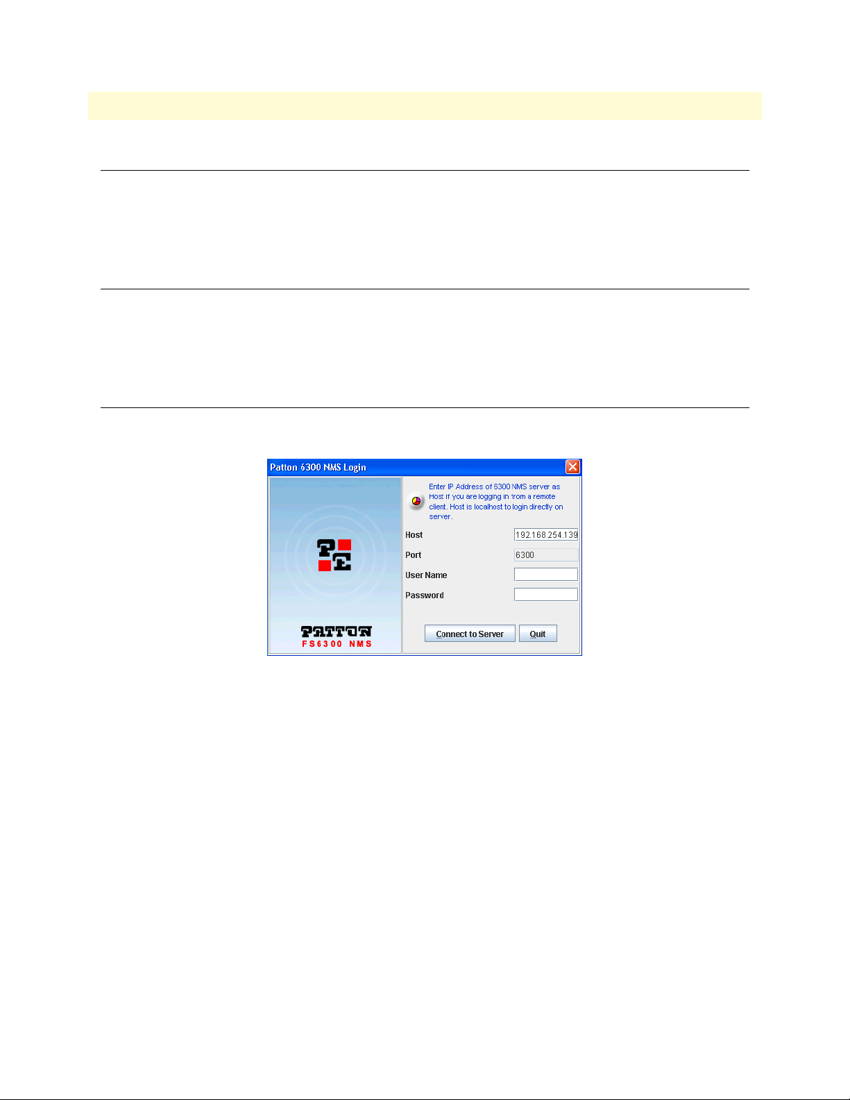
Figure 1. Logging in to the application client
In the Host field, enter 192.168.254.1 for the server address.
In the Port field, enter 6300 .
Enter the User ID assigned to you in the User ID field. If you do not have a User ID, contact your system
administrator. For unconfigured systems, the default User ID is superuser.
Enter the password assigned to you in the Password field. To learn how to configure your password, see
“Configuring Your Password” on page 17. For unconfigured systems, the default password is superuser .
Click Connect .
The Application Client console is displayed (if you had opted for it). The splash screen with a progress bar is
shown before the Application Client is completely opened.
Bringing up the NMS Server from Linux
Page 17

17
1.
2.
3.
FS6300 NMS Getting Started Guide
1 • Introduction
Configuring Your Password
Configuring your password before connecting to the client
When you log on to the Application Client for the first time, a Password Confirmation dialog box is displayed(only if this has been enabled by your administrator). If you do not see this dialog box, then ignore this
section and perform the steps explained in the next section, “Configuring your password from the client” on
page 17 .
To configure your password before connecting to the client:
In the Password Confirmation dialog box, click Reuse to continue using the same password for the same
period as previously configured. To enter a new password, click Configure and perform further steps.
Enter the new password in the Type new password field.
Re-enter the same password in the Confirm new password field.
4. Enter the number of days you want your password to be valid in Password expiry duration. If no value or
zero is entered in this field, then the password never expires.
5. Click Connect.
The new password is assigned to you and you are connected to the Application Client. You need to use this
new password from the subsequent login.
Configuring your password from the client
1. After logging into the client, select Security Administration from the Tools menu. Select the user from the
users list, and click Edit in the Menu bar. Select Change Password. The Password Configurator window is
displayed.
2. Enter the new password in the New Password field.
3. Re-enter the same password in the Confirm Password field.
4. Click OK. The new password is assigned to the user.
Logging into the Application Client
Page 18

FS6300 NMS Getting Started Guide 1 • Introduction
Troubleshooting
Table 1 lists the messages that are displayed in certain situations during the login process.
Table 1. Troubleshooting messages
Message Why am I getting this? What do I do?
You are logged in for the first time;
would you like to reuse the existing
password or configure a new password? (See “Configuring your pass-
word before connecting to the client”
on page 17).
This pop-up message is displayed
when you log on to the Application
Client for the first time (only if this has
been enabled by your administrator).
Refer to “Configuring your password
before connecting to the client”
page 17 for the procedure.
on
Your password has expired. Would
you like to reuse the old password or
configure a New password?
This User account has Expired. Please
contact the Administrator for further
details
This User account is Disabled. Please
contact the Administrator for further
details
Your password has expired.
Your user account has expired. The
user account is created by your system administrator.
• Your user account has been dis-
abled by your system administrator.
• Also, if your consecutive login
attempts fail for a certain number
of retries (number is configured by
the administrator), the user
account is automatically disabled.
• You can either set a new password
or retain the old password.
• Click Reuse to keep the same pass-
word and for the same expiration
period configured before.
• Click Configure to enter a new
password. Refer to “Configuring
your password before connecting to
the client”
cedure.
on page 17 for the pro-
• If you do not have the permission
to set your password, contact your
system administrator.
Contact your system administrator to
renew your user account.
Contact your system administrator to
enable your user account.
Logging into the Application Client 18
Page 19

FS6300 NMS Getting Started Guide 1 • Introduction
Table 1. Troubleshooting messages
Message Why am I getting this? What do I do?
Connection lost to the FS6300 NMS
server at <host>. Do you want to shutdown the client?
[Lock Screen dialog box] Please enter
your password to unlock the client
This message is displayed if the connection between the client and server
is lost due to network problems or if
the server is shut down abruptly.
This dialog box is displayed when the
Application Client is idle for more
than a specific period, that is, when
there is no interaction between the
user and the Application Client (no
mouse or keyboard events).
• Click Yes to shut down the client or
No to continue working.
• If you decide not to close the client
even after the connection is lost,
the screens, views, and data of the
client remain the same, but you
cannot perform any further operations in the client and no updates
occur. You need to reopen the client and reconnect to the FS6300
NMS Server.
• Enter a valid password in the Pass-
word field and click Unlock to
resume working on the Application
Client.
• To disable this prompt every time
the Application Client is idle (only
for that session), select Don't show
this dialog for the current session
any more
• Only specific number of unsuccess-
ful logins are allowed. When
exceeded, the session with Application Client is forcefully terminated and you need to reopen the
Application Client.
FS6300 NMS Application Client has
been terminated
• This message is displayed when
the Application Client is idle for
more than a specified period, that
is, when there is no interaction
between the user and the Application Client.
Bring up/reopen the client again.
• The Application Client is termi-
nated.
Logging into the Application Client 19
Page 20

FS6300 NMS Getting Started Guide 1 • Introduction
Using the NMS Menus and Toolbars
The following toolbars are always available at the top of the main window of the NMS:
• SetUp(F)
• Tools
• DS0 Mapping
• Help
• Reports
Additionally, some options in the menu tree have other toolbars at the top related to their function in the network:
• Fault Management - Network Events
• Fault Management - Alarms
• Performance - Configured Collection
• Administration Tools - Policies
Also, right-clicking on a device in the main window will display a menu of options available for that specific
device.
Logging out of the Application Client
To log out, perform any of the following procedures:
• From the SetUp(F) menu at the top of the screen, choose Exit.
• Press Alt+F4.
A Confirmation Message dialog box is displayed. Click Yes to quit the client.
Using the NMS Menus and Toolbars 20
Page 21

Chapter 2 Discovering Your Network
Chapter contents
Introduction..........................................................................................................................................................22
Starting the Discovery Process ...............................................................................................................................22
Viewing Node Information After Discovery ..........................................................................................................24
Configuring Multiple Cards ..................................................................................................................................24
Updating the Configuration ............................................................................................................................24
Saving the Configuration ................................................................................................................................26
Forcing Discovery for Selected Cards ..............................................................................................................26
Re-Discovering Cards............................................................................................................................................27
21
Page 22
FS6300 NMS Getting Started Guide 2 • Discovering Your Network
Introduction
The first task that you should perform with the FS6300 NMS is discovering your network. This chapter
describes how to start the Discovery process and how to configure subnet properties.
Starting the Discovery Process
Before starting the Discovery process, at least one node must be deployed, powered up, and connected to the
network. To start Discovery:
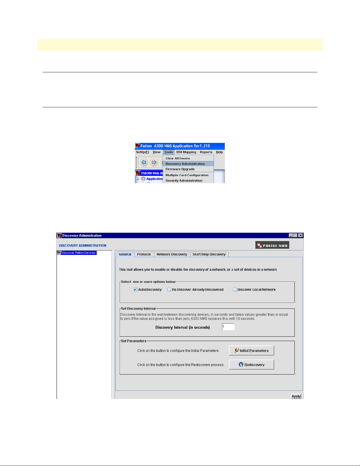
1. From the Tools menu at the top of the screen, select Discovery Administration.
The Discovery Window displays.
Figure 2. Tools > Discovery Administration
2. Click on Discover Patton Devices in the tree on the left side of the screen.
3. A window will display with the message, “AutoDiscovery currently DISABLED”. Click OK.
4. Click on the Auto-Discovery checkbox.
Figure 3. Discovery Window
Introduction 22
Page 23
FS6300 NMS Getting Started Guide 2 • Discovering Your Network
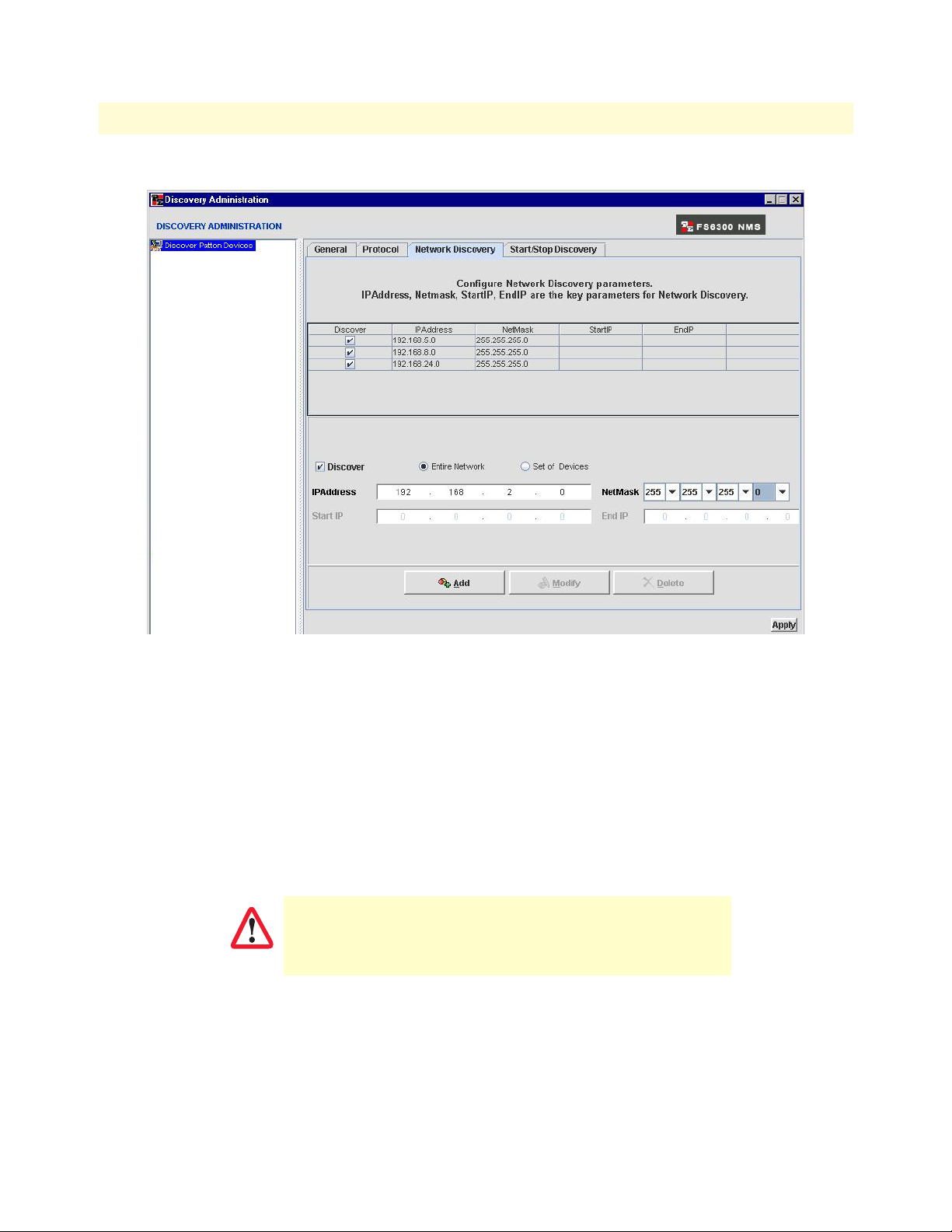
5. Click on the Network Discovery tab at the top of the Discovery Administration window.
Figure 4. Network Discovery tab
6. Enter the IP Address of the Subnet to be discovered by the FS6300 NMS. Click Add.
7. Click Apply to begin the Discovery process.
8. Returning to the main window, click on Networks (under Network Database) in the menu tree to see if the
IP subnet has already been entered into the Networks table for discovery.
Note The discovery process may take some time, depending on how many nodes
there are to discover on your network. During the Discovery process, a blue
icon with an actively spinning wheel will be in the upper right-hand corner
of the main window.
It is very important that you do not attempt to configure any
parameter during the Discovery process. Attempting to do so
IMPORTANT
could corrupt the data being collected during Discovery
.
When the NMS has collected enough information to identify the node, the node will be listed in the Nodes
table (under Network Database). As more information is collected through the Discovery process, entries will
appear in the FS6300 Geographical Areas section (under Network Maps).
Starting the Discovery Process 23
Page 24
FS6300 NMS Getting Started Guide 2 • Discovering Your Network
When the Discovery process is complete, the spinning wheel icon is replaced with a blue box containing a
white checkmark. Once Discovery is complete, a new subnet can be entered into the Network Discovery window (Tools > Discovery Administration).
Viewing Node Information After Discovery
If the discovered nodes weren’t individually configured prior to starting the Discovery process, they may be
missing information such as Node ID, Node POP, Network Area, Chassis Type, Geographical Area, and Chassis ID. For the nodes that are missing information, the FS6300 NMS will assign values for Geographical Area,
Node, and Chassis ID.
Clicking on a Chassis in the menu tree on the left side of the screen will display all of the discovered cards for
that Chassis in the main window. Clicking on the “+” box in the menu tree expands to show all of the slots for
that chassis. The main window also displays all of the cards for that chassis, including a quick look of which
slot each card is in and if there are currently any alarms for that slot. Hover the mouse over the card in the main
window to view a card’s IP address.
The next step after Discovery is to configure the Alarm Trap IP Address so that the NMS can receive and show
alarm indications for cards in the network. See Chapter 3, “Configuring Alarms and Clocking” on page 28 for
more information. For more information about viewing and configuring details for an individual device, see
Chapter 4, “Configuring and Managing Devices” on page 37.
Configuring Multiple Cards
If you have separate subnets that are supposed to be in the same Geographical Area but in a specifically named
Node and Chassis, you will want to update the subnet information so that is displayed as it actually is located
in the network.
Updating the Configuration
To configure multiple cards:
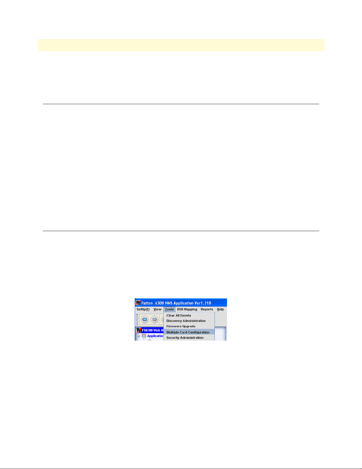
1. Select Tools from the menu at the top of the screen, then Multiple Card Configuration.
The Multiple Card Configuration window appears.
Figure 5. Tools > Multiple Card Configuration
Viewing Node Information After Discovery 24
Page 25
FS6300 NMS Getting Started Guide 2 • Discovering Your Network
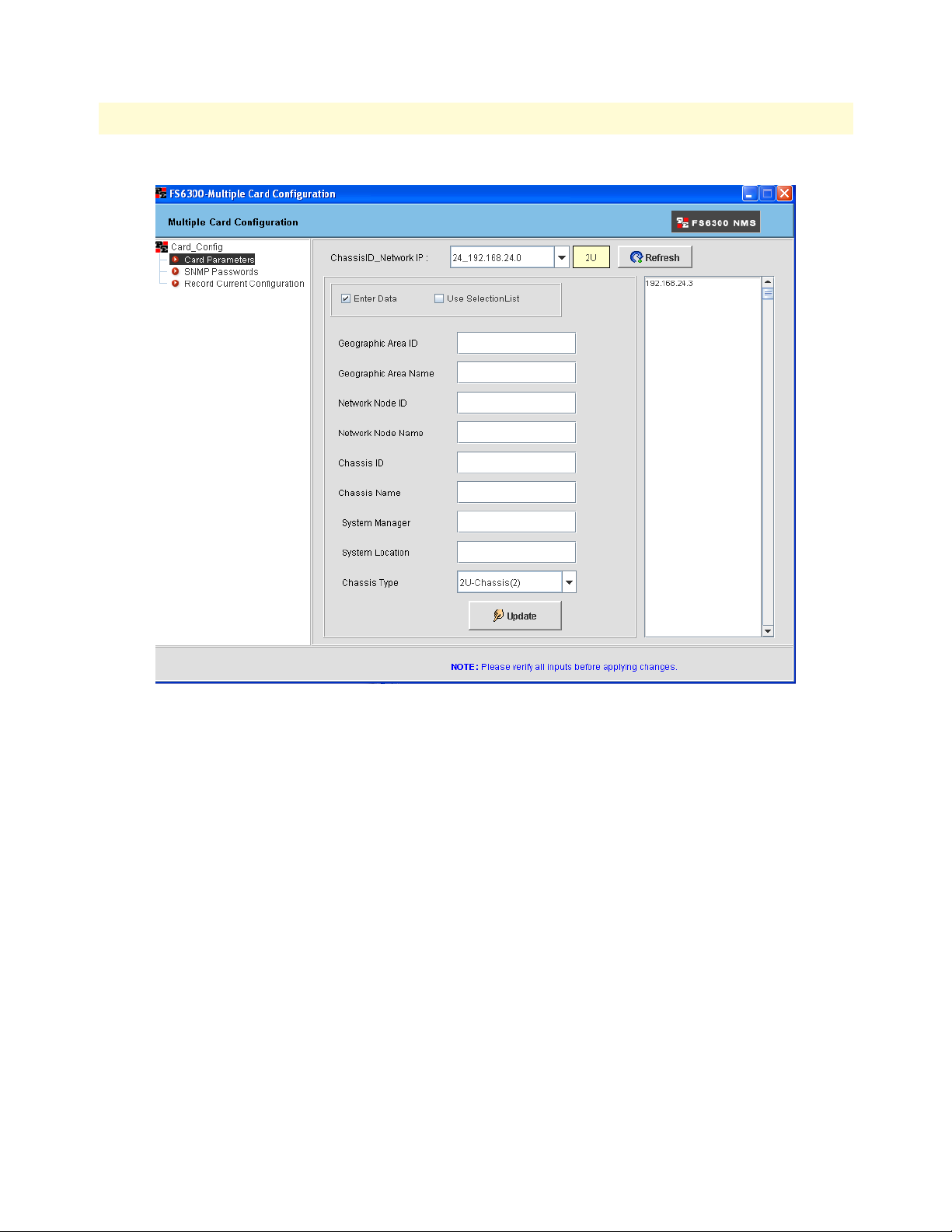
2. Click on Card Parameters in the menu tree on the left side of the screen.
Figure 6. Multiple Card Configuration > Card Parameters
3. Select the subnet you would like to update from the Network IP drop-down menu. The list on the right
side of the screen shows the IP addresses of all the devices discovered on that specific subnet.
4. Enter the information you would like to update on the subnet for the following fields:
– Geographical Area ID (Integer that identies the geographical area)
– Geographical Area Name (Descriptive name of the geographical area)
– Network Node ID (Integer used to identify the node on the network)
– Network Node Name (Descriptive name of the node)
– Chassis ID (Integer used to identify the chassis on the network)
– Chassis Name (Descriptive label for the chassis)
– System Manager (Name of the person managing this subnet on the network)
– System Location (Description of where the system is located)
– Chassis Type (Choose a chassis type from the drop-down menu)
5. Click Update to save the information for all of the cards on that subnet.
Configuring Multiple Cards 25
Page 26
FS6300 NMS Getting Started Guide 2 • Discovering Your Network
Note After clicking Update, it is very important to save this information in the
cards’ non-volatile memory so that the values will not be lost in case of a
power failure or card reboot.
Saving the Configuration
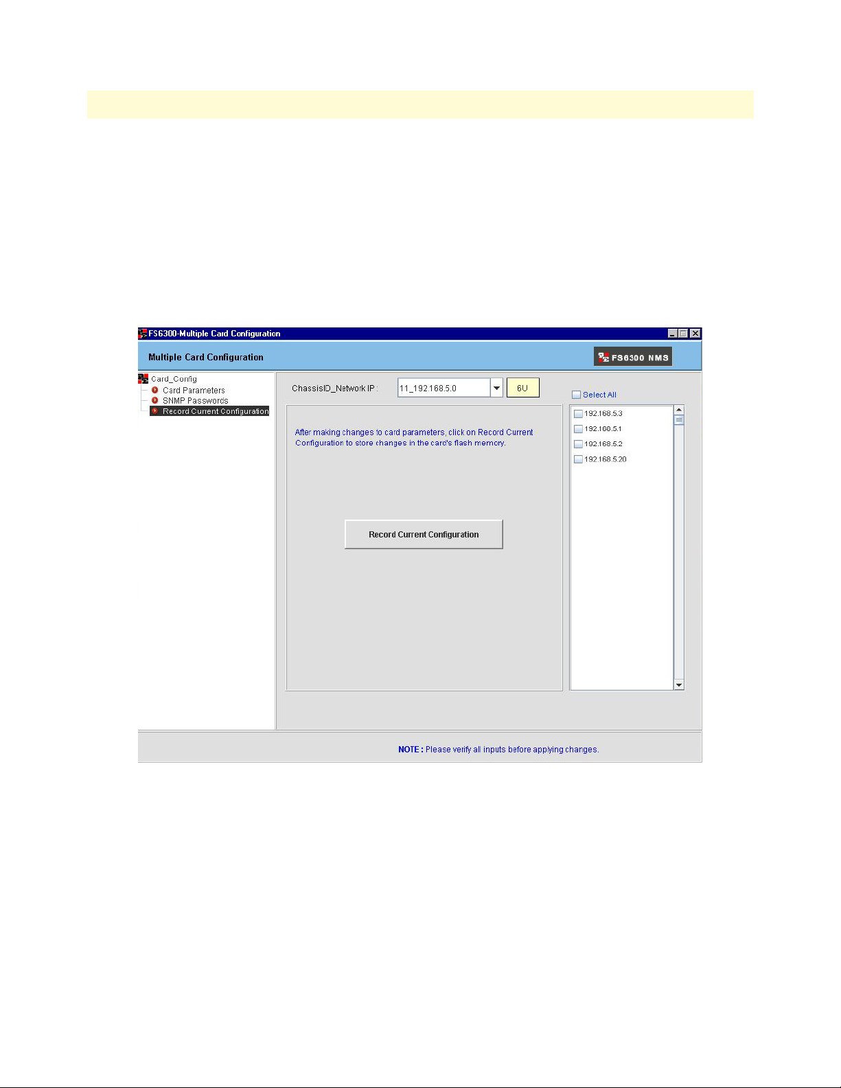
To save the information to non-volatile memory:
1. Click on Record Current Configuration in the menu tree on the left side of the screen. This will save all
current configurations in non-volatile memory for the devices listed in the panel on the right side of the
screen.
Figure 7. Multiple Card Configuration > Record Current Configuration
Forcing Discovery for Selected Cards
Though the cards have the updated information saved, the NMS will not display the changes until the cards
have been re-discovered. To re-discover specific cards and not the entire subnet, see “Re-Discovering Cards” on
page 27.
Configuring Multiple Cards 26
Page 27
FS6300 NMS Getting Started Guide 2 • Discovering Your Network
Re-Discovering Cards
You should re-discover cards after changing a card’s configuration, or if you have added a new chassis or devices
to the network.
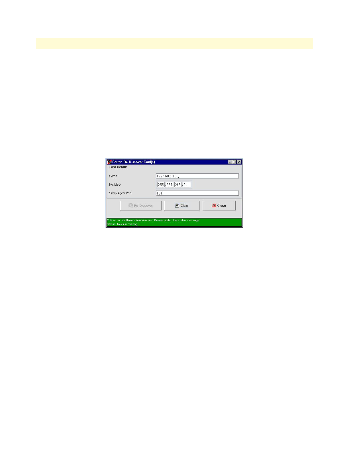
To re-discover cards:
1. Right-click on the device icon. You can do this in the Geographical Area, Network Node, Chassis, or Card
sections of Network Maps.
2. Select Re-Discover Cards from the pull-down menu.A window displays with information about the
card(s), including IP address, netmask, and SNMP Agent port.
3. Click Re-Discover. A message displays at the bottom of the box: “This action will take a few minutes.
Please watch the status message. Status: Re-discovering...”
Figure 8. Re-Discover Cards
Re-Discovering Cards 27
Page 28

Chapter 3 Configuring Alarms and Clocking
Chapter contents
Introduction..........................................................................................................................................................29
Configuring the Alarm Trap Manager ...................................................................................................................29
Configuring Alarms through the Network Node .............................................................................................29
Configuring Alarms through a Card in the Chassis .........................................................................................30
Alarm Indications ...........................................................................................................................................32
Viewing a Summary of Alarms ..............................................................................................................................32
Configuring Clocking Synchronization .................................................................................................................33
Refreshing the alarms after configuring clocking .............................................................................................34
Configuring Card System Clocking.......................................................................................................................34
28
Page 29
FS6300 NMS Getting Started Guide 3 • Configuring Alarms and Clocking
Introduction
Before you can receive alarm indications, you must first configure the alarms and clocking for the NMS. When
you discover your network for the first time, there will be alarms because the synchronization clocking has not
been fully configured yet.
Configuring the Alarm Trap Manager
In order to configure alarms, you need to configure the IP address of the NMS server which traps the alarm
reports from each of the cards in the network. By default, the Alarm Trap IP address is 0.0.0.0, so no alarms are
detected by the NMS.
You can configure the Alarm Trap Manager in two different ways, by right-clicking on a network node in the
Geographical Areas section, or by right-clicking on a card in the Chassis section.
Configuring Alarms through the Network Node
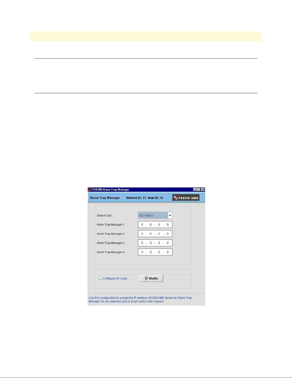
To configure the IP address for the Alarm Trap field for each card:
1. From the menu tree on the left side of the screen, select the Geographical Area for the node that you want
to configure.
2. In the main window, right-click on the Network Node, then select Alarm Trap Manager.
The Configure Alarm Trap Manager window dispalys. You may configure the Alarm Trap Manager for
any particular card in the chassis’ subnet or you can configure all of the cards in the subnet at once.
Figure 9. Alarm Trap Manager
3. Select the card that you would like to configure from the Select Card drop-down menu. If you would like
to configure all of the cards at the same time, select the Configure All Cards checkbox at the bottom of the
screen.
Introduction 29
Page 30
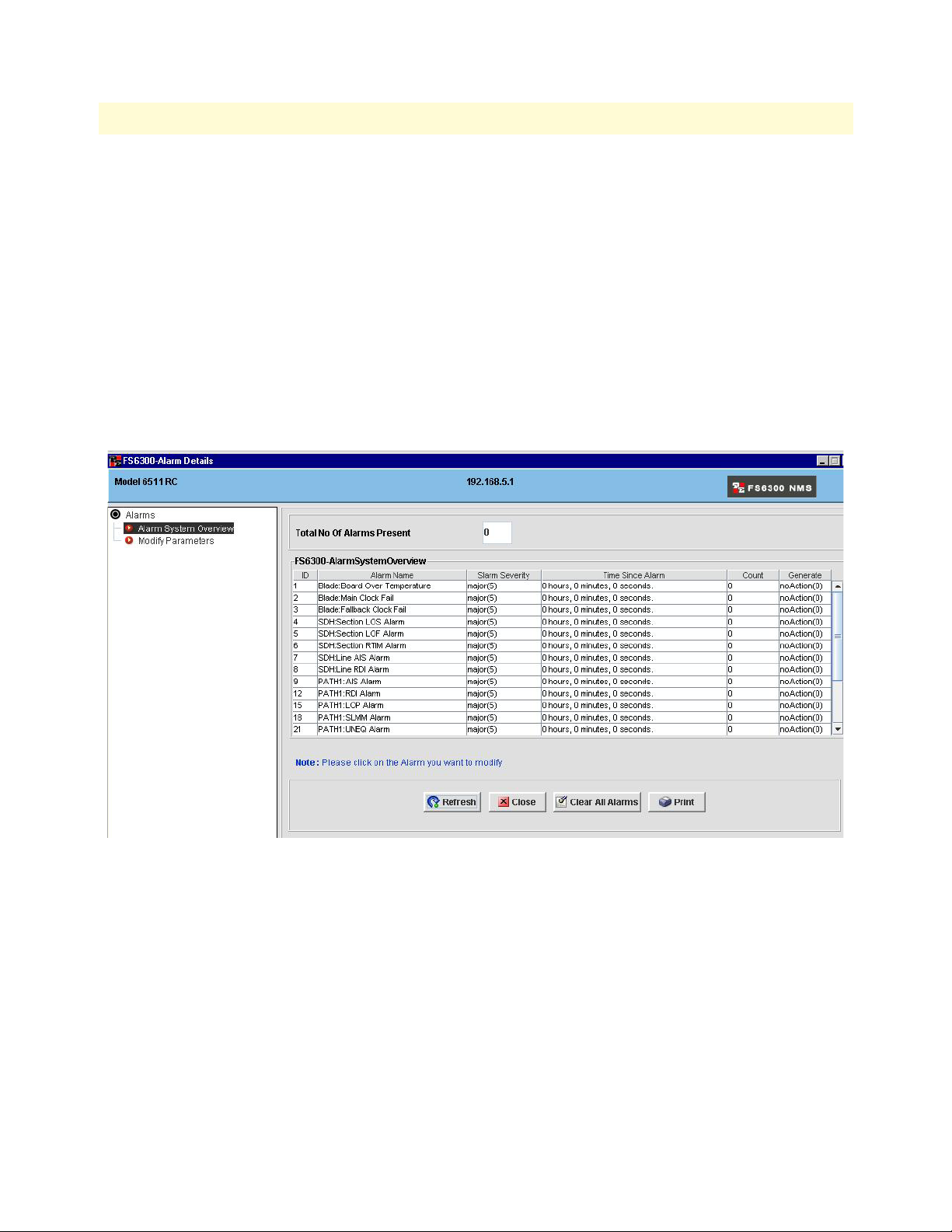
FS6300 NMS Getting Started Guide 3 • Configuring Alarms and Clocking
4. Enter the IP address of the NMS server in the Alarm Trap Manager 1 field.
5. Click the Modify button.
6. If the configuration was successful, a “Configuration Result” window displays. Click OK.
Configuring Alarms through a Card in the Chassis
To configure the IP address for the Alarm Trap field for each card:
1. From the menu tree on the left side of the screen, select the Chassis for the card that you want to config-
ure.
2. In the main window, right-click on the Card, then select Alarm Parameter Configuration.
The FS6300 Alarm Details window appears. Click on the Alarm System Overview to view information
about the alarms.
Figure 10. View Alarm Details
Alarm System Overview: The Alarm System Overview window shows the entire alarm system, including
the following information for each alarm:
– Alarm Name
– Alarm Severity
– Time Since Alarm
– Count– the number of times this alarm has occurred since being cleared
Configuring the Alarm Trap Manager 30
Page 31

FS6300 NMS Getting Started Guide 3 • Configuring Alarms and Clocking
3. Click on Modify Parameters to configure the alarms.
Figure 11. Modify Alarm Details
Modify Parameters: Configure the FS6300 Alarm Parameters through the Modify Parameters window.
– Alarm Syslog Priority
– Board Temperature Threshold
– Current Board Temperature
– Alarm Trap Managers 1-4
4. Click Modify to save your configuration in the card’s volatile memory.
5. Return to the Alarm Systems Overview screen. Before the most severe active alarm is propagated to the
icons in the NMS, you must first do Steps 6-7.
6. Click on the Clear All Alarms button. You should receive a “Configuration Result” window indicating
success.
7. Click on the Refresh button.
8. Close the Alarm Details window.
9. Repeat Steps 2-8 for each card in the chassis. After this is completed, return to the view of the chassis in the
main NMS window.
Configuring the Alarm Trap Manager 31
Page 32

FS6300 NMS Getting Started Guide 3 • Configuring Alarms and Clocking
Alarm Indications
The following are symbols that appear on a card or node icon when the NMS receives an alarm:
• Critical: Red circle with a white “X”
• Major: Yellow circle with two black exclamation points
• Minor: Light yellow circle with a single black exclamation point
• No Alarm/Informational: Green circle with black checkmark
Alarms are propagated up to the next level throughout the Network Maps section in the menu tree.The Chas-
sis icon indicates an alarm alert if one or more of the cards have an alarm. On the Geographical Aera level, a
network node will also display alarm alerts if a card in a chassis has an alarm.
Viewing a Summary of Alarms
To view a summary of all systems with an alarm, click on Failed Systems (under Network Maps) in the menu
tree on the left side of the screen. The Failed Systems map shows all the cards that have alarm alerts.
The Alarm Summary View window always appears in the bottom left corner of the screen under the main
menu tree. It offers a quick glance at the status of alarms that are currently occurring in the system. You can
change how the Alarm Summary View is displayed by clicking on the icons in the Alarm Summary View window. There are three different view options:
• Tabular View
• Graphical View
• Pie Chart View
Figure 12. Alarm Summary View options (Tabular, Graphical, and Pie Chart)
Viewing a Summary of Alarms 32
Page 33

FS6300 NMS Getting Started Guide 3 • Configuring Alarms and Clocking
Configuring Clocking Synchronization
To configure clocking synchronization for a chassis:
1. From the menu tree on the left side of the screen, select Node (under Geographical Area).
2. In the main window, right-click on the chassis that you want to configure clocking for.
3. Select Chassis Clocking Synchronization from the pull-down menu.
Figure 13. Chassis Menu > Chassis Clocking Sync
The Chassis Clocking Synchronization window displays.
Figure 14. Modify System Clocking
4. Select Modify System Clocking from the menu tree on the left side of the screen.
5. Select a card from the Select Card drop-down menu, and select a clock from the Clock Reference drop-
down menu. The Clock Reference can be Master(1), Secondary(2), or Slave(3). Click Submit.
6. Repeat Step 5 for each card in the chassis.
Note A chassis can have only one master and one secondary, so if you accidentally
select another master in the same chassis, the NMS will not allow you to save
the clock for that card as the Master.
Configuring Clocking Synchronization 33
Page 34

FS6300 NMS Getting Started Guide 3 • Configuring Alarms and Clocking
Refreshing the alarms after configuring clocking
After you have configured clocking for the chassis, you can refresh the alarms that occurred before clocking was
configured. To refresh the alarms for a card:
1. Right-click on the card icon and select Alarm Parameter Configuration.
The FS6300 Alarm Details window displays (see Figure 10 on page 30).
2. Click on Alarm System Overview in the menu tree on the left side of the screen.
3. Click the Clear All Alarms button.
4. Click the Refresh button.
All of the alarms that were related to clocking should be cleared. (Other alarms not related to clocking may still
be present). The next step after configuring clocking synchronization is to configure clocking options for the
card system, including Clock Fallback and Clock Auto Recover.
Configuring Card System Clocking
In addition to setting a clock to Master, Secondary, or Slave, you must also select the source for clocking and
determine whether to enable or disable Clock Fallback and Clock Auto Recover. To configure card system
clocking:
1. Right-click on the card icon and select Card System Clocking.
Figure 15. Card Menu > Card System Clocking
The System Clocking window displays.
Configuring Card System Clocking 34
Page 35

FS6300 NMS Getting Started Guide 3 • Configuring Alarms and Clocking
2. Click on View System Clocking in the menu tree on the left side of the screen. From this window, you can
view and verify the configuration settings for the card’s entire clocking system, including whether any failures have occurred and if any clock-related alarms are active.
Figure 16. View System Clocking
3. To change any of the card’s clocking paramters, click on Modify System Clocking in the menu tree on the
left side of the screen.
Figure 17. Modify System Clocking
Configuring Card System Clocking 35
Page 36

FS6300 NMS Getting Started Guide 3 • Configuring Alarms and Clocking
The configurable parameters are:
– Main Reference
– Fallback Reference
– Clock Fallback
– Clock Auto Recover
Note Refer to the FS6300 Administrator’s Reference Guide for details on the func-
tion and significance of these parameters.
4. Click Submit to save your changes.
Configuring Card System Clocking 36
Page 37

Chapter 4 Configuring and Managing Devices
Chapter contents
Introduction..........................................................................................................................................................38
Adding Devices .....................................................................................................................................................38
Working with Network Maps................................................................................................................................39
Geographical Areas .........................................................................................................................................39
Nodes .............................................................................................................................................................39
Chassis ............................................................................................................................................................39
Slots/Devices ...................................................................................................................................................39
Ports/Interfaces ...............................................................................................................................................39
Managing Operator Actions ..................................................................................................................................40
Record the current configuration ....................................................................................................................40
Reboot the device ............................................................................................................................................40
Set the factory default configuration ...............................................................................................................41
Configuring Cards.................................................................................................................................................42
Viewing LEDs ................................................................................................................................................42
37
Page 38

FS6300 NMS Getting Started Guide 4 • Configuring and Managing Devices
Introduction
Devices can be individually configured and monitored through the FS6300 NMS. The NMS organizes devices
by geographical area in the Network Maps section of the menu tree, where device-specific menus can be
viewed by right-clicking on a device. Devices can also be monitored through the Network Database section of
the menu tree.
This chapter describes what information you can find and configure about specific devices through the Network Maps and Network Database sections of the FS6300 NMS.
Adding Devices
To add individual devices to the FS6300 NMS:
1. Click Setup(F) at the top of the screen, then click Add Device(o).
, press Ctrl+O. The Add SNMP Device window appears.
OR
Figure 18. Add SNMP Device window
2. Enter the IP address and Netmask of the device you want to add.
3. If desired, you may modify the SNMP Password and SNMP Agent Port.
4. If you don’t want to monitor the status of your request to add this device to the system, select the checkbox
for Process Add SNMP Device request in the background.
5. Click Add Device.
Introduction 38
Page 39

FS6300 NMS Getting Started Guide 4 • Configuring and Managing Devices
Working with Network Maps
The Network Maps section of the NMS shows a map of the devices located on the network at various levels.
Figure 19. Network Maps
Geographical Areas
Click on a Geographical Area in the main menu tree to view a map of Network Nodes in the NMS.
Right-click on the icon of a Network Node in the main window to view a pull-down menu of options.
Nodes
Click on a Network Node in the main menu tree to view a map of Chassis in that node.
Right-click on the icon of a Chassis in the main window to view a pull-down menu of options..
Chassis
Click on a Chassis in the main menu tree to view a map of Devices in that chassis.
Right-click on the icon of a Device in the main window to view a pull-down menu of options..
Slots/Devices
Click on a Device in the main menu tree to view a map of Ports in that device.
Right-click on the icon of a Port in the main window to view a pull-down menu of options.
Ports/Interfaces
Right-click on a port to configure its link or set it to be managed or unmanaged.
Working with Network Maps 39
Page 40

FS6300 NMS Getting Started Guide 4 • Configuring and Managing Devices
Managing Operator Actions
Operators may want to reboot a device or save the current configuration to memory, in case problems arise in
the system. To reach the Operator Actions menu, right-click on the Device icon and select Operator Actions.
Figure 20. Operator Actions > Reset Options window
Record the current configuration
To save the current configuration of a device to memory:
1. In the main menu tree under Network Maps, navigate to the Chassis or Card/Slot.
2. Right-click on the card’s icon in the main window and select Operator Action. The Reset Options win-
dow appears. It shows the card model, IP address, and software revision of the card.
Figure 21. Record Current Configuration
3. Select Record Current Configuration from the menu tree in the Reset Options window.
4. Click the Record Current Configuration button.
Reboot the device
To reboot a chassis or card:
1. In the main menu tree under Network Maps, navigate to the Chassis or Card/Slot.
2. Right-click on the card’s icon in the main window and select Operator Action. The Reset Options win-
dow appears. It shows the card model, IP address, and software revision of the card.
Managing Operator Actions 40
Page 41

FS6300 NMS Getting Started Guide 4 • Configuring and Managing Devices
Figure 22. Hard Reset
3. Select Hard Reset from the menu tree in the Reset Options window.
4. Click the Hard Reset button.
Set the factory default configuration
To set the factory default configuration for a device:
1. In the main menu tree under Network Maps, navigate to the Chassis or Card/Slot.
2. Right-click on the card’s icon in the main window and select Operator Action. The Reset Options win-
dow appears. It shows the card model, IP address, and software revision of the card.
Figure 23. Set Factory Default Configuration
3. Select Set Factory Default Configuration from the menu tree in the Reset Options window.
4. Click the Set Factory Default Configuration button.
5. Click the Hard Reset button.
The Hard Reset process will reset ALL of the system’s values to
the original factory settings. After resetting these values, the system will continue to function the same until the system is reboo-
IMPORTANT
Managing Operator Actions 41
ted.
Page 42

FS6300 NMS Getting Started Guide 4 • Configuring and Managing Devices
Configuring Cards
See the following chapters for information on configuring specific cards:
• 2616RC – Chapter 5, “Configuring the 2616RC Card” on page 43
• 3096RC – Chapter 6, “Configuring the 3096RC Card” on page 56
• 6511RC – Chapter 7, “Configuring the 6511RC Card” on page 76
Viewing LEDs
To view the real-time LEDs of a chassis or card:
1. Navigate to Network Maps in the menu tree, then right-click on the card or chassis icon in the main win-
dow.
2. Click on Chassis Unit GUI or Card Front Panel GUI.
3. A graphic of the front panel displays. The LEDs are shown in real-time.
Configuring Cards 42
Page 43

Chapter 5 Configuring the 2616RC Card
Chapter contents
Introduction..........................................................................................................................................................44
2616RC Configuration Menu ...............................................................................................................................44
Viewing the Front Panel........................................................................................................................................45
Configuring the Card System ................................................................................................................................45
Modify System Parameters ..............................................................................................................................45
View System Status .........................................................................................................................................46
View System Status Details .............................................................................................................................46
View Ethernet Status .......................................................................................................................................46
View SNMP/HTTP Parameters .....................................................................................................................46
Configuring Ethernet Settings ...............................................................................................................................47
Modify Ethernet Parameters ...........................................................................................................................47
View Ethernet Statistics ..................................................................................................................................47
Viewing Events and Alerts .....................................................................................................................................48
Exporting/Importing the Configuration ................................................................................................................48
Exporting the Configuration ...........................................................................................................................48
Importing the Configuration ..........................................................................................................................49
Configuring IP Routing.........................................................................................................................................50
Add Route ......................................................................................................................................................50
Viewing the System Log ........................................................................................................................................51
Modify Syslog Configuration ..........................................................................................................................51
Change Alarm Status ......................................................................................................................................51
Configuring the T1/E1 Ports.................................................................................................................................52
View Configuration ........................................................................................................................................52
Modify Line Interface Settings ........................................................................................................................52
Modify Test Settings .......................................................................................................................................53
Set Channel Assignments ................................................................................................................................54
View Line Status .............................................................................................................................................54
Viewing T1/E1 Reports.........................................................................................................................................55
Viewing the T1/E1 Map Layer ..............................................................................................................................55
43
Page 44

FS6300 NMS Getting Started Guide 5 • Configuring the 2616RC Card
Introduction
The Patton Model 2616RC is a digital cross-connect with 16 T1/E1 ports. There are several ways to reach the
configuration menu for the 2616RC card:
• Click on Network Maps in the main menu tree, then click on Chassis. Right-click on the 2616RC icon.
• Select the 2616RC card from the main menu tree, then right-click on the card icon in the main window.
• Navigate to Network Database > Managed Objects > Cards in the main menu tree, then right-click on the
IP address of the card in the table in the main window.
The best way to reach the configuration menu for a card is to select the card in the main menu tree, then rightclick on the card’s icon in the main window.
2616RC Configuration Menu
The following options are available in the pull-down menu for the 2616RC card:
Figure 24. 2616RC Configuration Menu
• Card Overview – Shows information for Box Status, Card Info, and Alarm Info
• Alarm Parameter Configuration – See “Configuring the Alarm Trap Manager” on page 29 in Chapter 3
• Card Front Panel GUI – See “Viewing the Front Panel” on page 45
• Card System Clocking – See “Configuring Card System Clocking” on page 34 in Chapter 3
• Card System Configuration – See “Configuring the Card System” on page 45
• Ethernet Overview – See “Configuring Ethernet Settings” on page 47
Introduction 44
Page 45

FS6300 NMS Getting Started Guide 5 • Configuring the 2616RC Card
• Events and Alerts – See “Viewing Events and Alerts” on page 48
• Export Import Configuration – See “Exporting/Importing the Configuration” on page 48
• IP Routing – See “Configuring IP Routing” on page 50
• Operator Action – See “Managing Operator Actions” on page 40 in Chapter 4
• PPP Configuration – See “Configuring PPP” on page 53
• System Log – See “Viewing the System Log” on page 51
• T1E1 Port Configuration – See “Configuring the T1/E1 Ports” on page 52
• T1E1 Reports – See “Viewing T1/E1 Reports” on page 55
• Re-Discover Card – See “Re-Discovering Cards” on page 27 in Chapter 2
• Display T1E1 Map Layer – See “Viewing the T1/E1 Map Layer” on page 55
• UnManage – See Chapter 9, “Monitoring Managed Objects” on page 97
Viewing the Front Panel
Click on Card Front Panel GUI to view the front panel of the card in real-time.
Figure 25. 2616RC Front Panel LEDs
Configuring the Card System
Click on Card System Configuration to configure system parameters. You can also view the system status, ethernet status, system parameters, SNMP/HTTP parameters, and system status details.
Modify System Parameters
If you only want to view the system parameters, click on View System Parameters in the Card System Config-
uration window.
To configure the card system, click on Modify System Parameters in the menu tree in the Card System Configuration window (see Figure 24 on page 44).
Viewing the Front Panel 45
Page 46

FS6300 NMS Getting Started Guide 5 • Configuring the 2616RC Card
Figure 26. Modify 2616RC Card System Parameters
1. Enter the country where the card is located in the Country text field.
2. Enter a description for the card in the Module Name text field.
3. Select to enable or disable graphics from the Web Settings drop-down menu.
4. Select a privilege option from the Monitor Privilege drop-down menu.
5. Select how often you would like to refresh statistics information from the Stats Refresh Rate drop-down
menu.
6. Select to enable or disable front handle information from the Front Handle Reset drop-down menu.
7. Click Modify to save your changes. Click Refresh.
View System Status
Click on View System Status in the Card System Configuration window to see an overview of the physical sta-
tus of the card and the system status. View System Status shows information about the handle switches, front/
rear LEDs, alarm and clock LEDs, and the board temperature.
View System Status Details
Click on View System Status Details in the Card System Configuration window to see information on CPU
statistics, Message Block statistics, Memory statistics, Manufacturer details, and the Enclosure System temperature.
View Ethernet Status
Click on View Ethernet Status in the Card System Configuration window to see the LEDs and speeds of the
card’s Ethernet ports.
View SNMP/HTTP Parameters
Click on View SNMP/HTTP Parameters in the Card System Configuration window to see the SNMP ver-
sion and passwords.
Configuring the Card System 46
Page 47
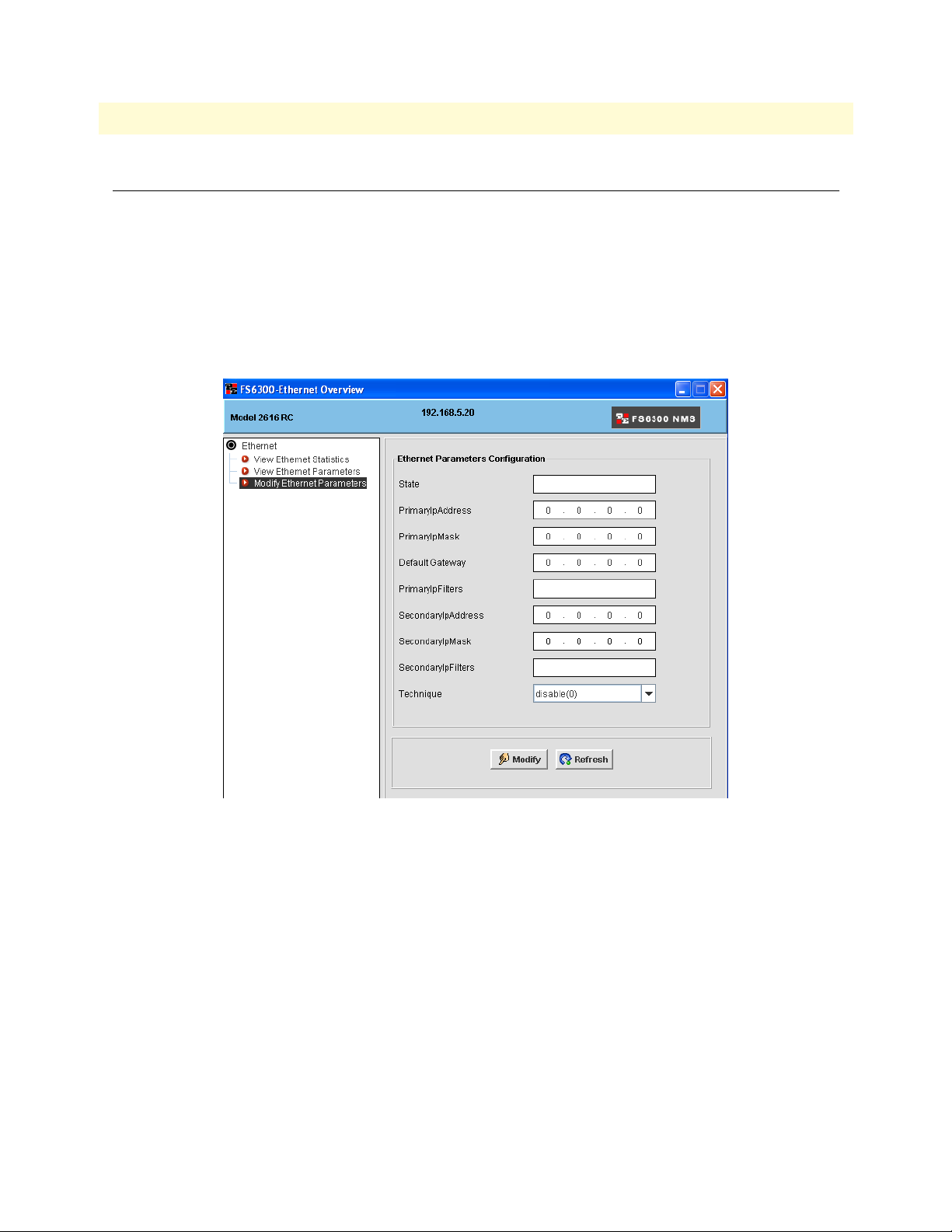
FS6300 NMS Getting Started Guide 5 • Configuring the 2616RC Card
Configuring Ethernet Settings
Click on Ethernet Overview to configure Ethernet settings. You can also view Ethernet statistics.
Modify Ethernet Parameters
If you only want to view the Ethernet parameters, click on View Ethernet Parameters in the Ethernet Over-
view window.
To configure the Ethernet settings, click on Modify Ethernet Parameters in the menu tree in the Ethernet
Overview window (see Figure 27).
Figure 27. Modify 2616RC Ethernet Parameters
1. Enter the main address and mask for the card in the Primary IP Address and IP Mask fields.
2. If desired, enter a secondary address and mask in the Secondary IP Address and IP Mask fields.
3. Select static or disable the technique in the Technique drop-down menu.
4. Click Modify to save your changes. Click Refresh.
View Ethernet Statistics
Click on View Ethernet Statistics in the Ethernet Overview window to view statistics for the Ethernet ports on
the device, such as errors and frame stats.
Configuring Ethernet Settings 47
Page 48

FS6300 NMS Getting Started Guide 5 • Configuring the 2616RC Card
Viewing Events and Alerts
Click on Events and Alerts to view a color-coded chart that shows the amount of alarms and severity of alarms
for the card.
Figure 28. 2616RC Events and Alerts
Exporting/Importing the Configuration
Click on Export/Import Configuration to save or load a configuration file.
Exporting the Configuration
To save the current configuration, click on Export Configuration in the menu tree of the window, then click
Export to save the current configuration to a file.
Figure 29. Export Configuration
Viewing Events and Alerts 48
Page 49

FS6300 NMS Getting Started Guide 5 • Configuring the 2616RC Card
Importing the Configuration
To load a configuration file, click on Import Configuration in the menu tree of the window, then click Browse
to select the configuration file you want to load. Click Import to load the file.
Figure 30. Import Configuration
Exporting/Importing the Configuration 49
Page 50

FS6300 NMS Getting Started Guide 5 • Configuring the 2616RC Card
Configuring IP Routing
Click on IP Routing to add routes and view routing information. The IP Overview window shows details for
routing destinations, and includes information for gateway, cost, interface, protocol, and state of each route.
Figure 31. Add a New Route to 2616RC
Add Route
To add an IP route:
1. Click the Add button in the IP Overview window.
2. Enter a destination address for the new route.
3. Enter a gateway address for the new route.
4. Click Define Route.
Configuring IP Routing 50
Page 51
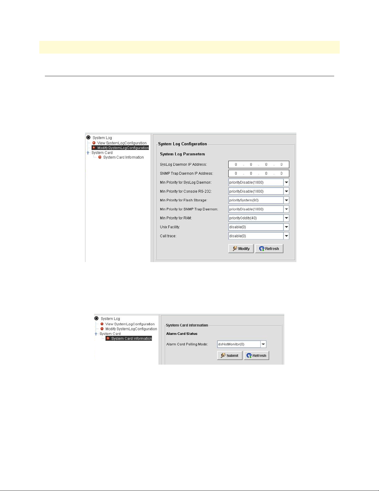
FS6300 NMS Getting Started Guide 5 • Configuring the 2616RC Card
Viewing the System Log
Click on System Log to view and modify syslog information.
Modify Syslog Configuration
If you only want to view the syslog configuration, click on View SystemLog Configuration in the System Log
window. To configure the syslog information, click on Modify SystemLog Configuration in the menu tree in
the Syslog window.
Figure 32. Modify System Log
Change Alarm Status
To change the alarm status of the 2616RC card:
1. Click on System Card Information in the System Log window.
Figure 33. Set System Card Alarm Status
2. Select an option for the card from the Alarm Card Polling Mode drop-down menu.
3. Click Submit.
Viewing the System Log 51
Page 52

FS6300 NMS Getting Started Guide 5 • Configuring the 2616RC Card
Configuring the T1/E1 Ports
Click on T1E1 Port Configuration to configure line interfaces, test settings, and channel assignments for T1/
E1 ports.
View Configuration
In the T1/E1 Link Configuration window, click on Configuration > View Configuration. Select a link to view
the line interface settings and test settings.
Modify Line Interface Settings
Figure 34. 2616RC T1/E1 Link Configuration window
1. In the T1/E1 Link Configuration window, click on Configuration > Line Interface Settings > Modify
Line Settings.
2. Select a link from the drop-down menu at the top of the window.
3. Edit the desired options:
– Circuit Identifier
– Line Type: Other / ESF / D4 / E1 / E1-CRC / E1-MF / E1-CRC-MF / E1-Transparent
– Line Coding: B8ZS / HDB3 / 2BTS1 / AM1 / Other
– Receive Equalizer: Off / On
– Receiver Sensitivity: Level 1-7
– Line Build Out: triState / e1pulse / t1pulse0dB / t1pulse-7dB / t1pulse-15dB
– Yellow Alarm Format: Bit2 / DL / Frame12FS
– Fdl: Other / Ansi-T1-403 / Att-54016 / Fdl-name
4. Click Submit to save your changes.
Configuring the T1/E1 Ports 52
Page 53

FS6300 NMS Getting Started Guide 5 • Configuring the 2616RC Card
Modify Test Settings
Figure 35. 2616RC T1/E1 Test Settings
1. In the T1/E1 Link Configuration window, click on Configuration > Test Settings > Modify Test Settings.
2. Select a link from the drop-down menu at the top of the window.
3. Edit the desired options:
– Force Yellow Alarm: Auto / On / Disable
– Loopback Configuration: No Loop / Payload Loop / Line Loop / Other Loop
– Send Code: Send No Code / Send Line Code / Send Reset Code
– Error Injection: No Error Injection / Inject CRC Error Burst / Inject Line Error Burst
– Yellow Alarm Severity: Critical / Major / Minor / Info / Ignore
– Red Alarm Severity: Critical / Major / Minor / Info / Ignore
4. Click Submit to save your changes.
Configuring the T1/E1 Ports 53
Page 54

FS6300 NMS Getting Started Guide 5 • Configuring the 2616RC Card
Set Channel Assignments
Figure 36. 2616RC T1/E1 Channel Assignment
In the Channel Assignment section of the T1/E1 Link Configuration window, you can set all or individual
links to Frame Relay or PPP.
To set all links to Frame Relay or PPP:
1. Click the Frame Relay button to set all of the channels to Frame Relay.
2. Click the PPP button to set all of the channels to PPP.
You do not need to click Submit. The change will take effect immediately.
To set individual links to Frame Relay or PPP:
1. Select Frame Relay or PPP from the drop-down menu for that channel.
2. Repeat Step 1 for all of the individual channels you want to change.
3. Click Submit.
View Line Status
There are two types of line status statistics that you may view in the T1/E1 Link Configuration window – Near
End Line Status and Far End Line Status.
• Near End Line Status – Click on Current Near End Line Status to view statistics for current near end per-
formance. Click on Total Near End Line Status to view statistics totals for near end performance.
• Far End Line Status – Click on Current Far End Line Status to view statistics for current far end perfor-
mance. Click on Total Far End Line Status to view statistics totals for far end performance.
Configuring the T1/E1 Ports 54
Page 55

FS6300 NMS Getting Started Guide 5 • Configuring the 2616RC Card
Viewing T1/E1 Reports
Click on T1E1 Reports to view and print different reports about the activity, line interface settings, and test
settings of T1/E1 links on the 2616RC card.
Click the Print button to send the report to a printer on your network.
Click the Export to Excel button to send the report to Microsoft Excel to save in a spreadsheet.
Figure 37. 2616RC T1/E1 Reports
Viewing the T1/E1 Map Layer
Click on Display T1E1 Map Layer to show a map of all the T1/E1 ports on the card. Right-click on a port in
the map to configure its link.
Figure 38. 2616RC T1/E1 Port Map
Viewing T1/E1 Reports 55
Page 56

Chapter 6 Configuring the 3096RC Card
Chapter contents
Introduction..........................................................................................................................................................57
3096RC Configuration Menu ...............................................................................................................................57
Viewing the Front Panel........................................................................................................................................58
Configuring the Card System ................................................................................................................................58
Modify System Parameters ..............................................................................................................................58
View System Status .........................................................................................................................................59
View System Status Details .............................................................................................................................59
View Ethernet Status .......................................................................................................................................59
View SNMP/HTTP Parameters .....................................................................................................................59
Configuring Ethernet Settings ...............................................................................................................................60
Modify Ethernet Parameters ...........................................................................................................................60
View Ethernet Statistics ..................................................................................................................................60
Viewing Events and Alerts .....................................................................................................................................61
Exporting/Importing the Configuration ................................................................................................................61
Exporting the Configuration ...........................................................................................................................61
Importing the Configuration ..........................................................................................................................62
Configuring G.SHDSL Ports ................................................................................................................................63
Activating/Deactivating All Ports ....................................................................................................................63
Configuring Individual Ports ..........................................................................................................................64
View Port Information ..............................................................................................................................64
Edit CO/CPE Options ..............................................................................................................................65
Determine Best Payload Rate ....................................................................................................................66
Viewing G.SHDSL Reports...................................................................................................................................67
Configuring IP Routing.........................................................................................................................................68
Add Route ......................................................................................................................................................68
Viewing the System Log ........................................................................................................................................69
Modify Syslog Configuration ..........................................................................................................................69
Change Alarm Status ......................................................................................................................................69
Configuring the T1/E1 Ports.................................................................................................................................70
View Configuration ........................................................................................................................................70
Modify Line Interface Settings ........................................................................................................................70
Modify Test Settings .......................................................................................................................................71
Set Channel Assignments ................................................................................................................................72
View Line Status .............................................................................................................................................72
Managing Inband T1/E1 Channels .......................................................................................................................73
Adding a T1/E1 Management Channel ..........................................................................................................73
Viewing T1/E1 Reports.........................................................................................................................................74
Viewing the T1/E1 Map Layer ..............................................................................................................................75
Viewing the G.SHDSL Map Layer........................................................................................................................75
56
Page 57

FS6300 NMS Getting Started Guide 6 • Configuring the 3096RC Card
Introduction
The Patton Model 3096RC is a G.SHDSL TDM Concentrator with 16 G.SHDSL ports. There are several
ways to reach the configuration menu for the 3096RC card:
• Click on Network Maps in the main menu tree, then click on Chassis. Right-click on the 3096RC icon.
• Select the 3096RC card from the main menu tree, then right-click on the card icon in the main window.
• Navigate to Network Database > Managed Objects > Cards in the main menu tree, then right-click on the
IP address of the card in the table in the main window.
The best way to reach the configuration menu for a card is to select the card in the main menu tree, then rightclick on the card’s icon in the main window.
3096RC Configuration Menu
The following options are available in the pull-down menu for the 3096RC card:
Figure 39. 3096RC Configuration Menu
• Card Overview – Shows information for Box Status, Card Info, and Alarm Info
• Alarm Parameter Configuration – See “Configuring the Alarm Trap Manager” on page 29 in Chapter 3
• Card Front Panel GUI – See “Viewing the Front Panel” on page 58
• Card System Clocking – See “Configuring Card System Clocking” on page 34 in Chapter 3
• Card System Configuration – See “Configuring the Card System” on page 58
• Ethernet Overview – See “Configuring Ethernet Settings” on page 60
• Events and Alerts – See “Viewing Events and Alerts” on page 61
• Export Import Configuration – See “Exporting/Importing the Configuration” on page 61
Introduction 57
Page 58

FS6300 NMS Getting Started Guide 6 • Configuring the 3096RC Card
• G.SHDSL Port Configuration – See “Configuring G.SHDSL Ports” on page 63
• G.SHDSL Report – See “Viewing G.SHDSL Reports” on page 67
• Inband Channel Management-T1/E1 – See “Managing Inband T1/E1 Channels” on page 73
• IP Routing – See “Configuring IP Routing” on page 68
• Operator Action – See “Managing Operator Actions” on page 40 in Chapter 4
• PPP Configuration – See “Viewing the System Log” on page 69
• System Log – See “Viewing the System Log” on page 69
• T1E1 Port Configuration – See “Configuring the T1/E1 Ports” on page 70
• T1E1 Reports – See “Viewing T1/E1 Reports” on page 74
• Re-Discover Card – See “Re-Discovering Cards” on page 27 in Chapter 2
• Display T1E1 Map Layer – See “Viewing the T1/E1 Map Layer” on page 75
• Display G.SHDSL Map Layer – “Viewing the G.SHDSL Map Layer” on page 75
• UnManage – See Chapter 9, “Monitoring Managed Objects” on page 97
Viewing the Front Panel
Click on Card Front Panel GUI to view the front panel of the card in real-time.
Figure 40. 3096RC Front Panel LEDs
Configuring the Card System
Click on Card System Configuration to configure system parameters. You can also view the system status, ethernet status, system parameters, SNMP/HTTP parameters, and system status details.
Modify System Parameters
If you only want to view the system parameters, click on View System Parameters in the Card System Config-
uration window.
To configure the card system, click on Modify System Parameters in the menu tree in the Card System Configuration window (see Figure 39 on page 57).
Viewing the Front Panel 58
Page 59

FS6300 NMS Getting Started Guide 6 • Configuring the 3096RC Card
Figure 41. Modify 3096RC Card System Parameters
1. Enter the country where the card is located in the Country text field.
2. Enter a description for the card in the Module Name text field.
3. Select to enable or disable graphics from the Web Settings drop-down menu.
4. Select a privilege option from the Monitor Privilege drop-down menu.
5. Select how often you would like to refresh statistics information from the Stats Refresh Rate drop-down
menu.
6. Select to enable or disable front handle information from the Front Handle Reset drop-down menu.
7. Click Modify to save your changes. Click Refresh.
View System Status
Click on View System Status in the Card System Configuration window to see an overview of the physical sta-
tus of the card and the system status. View System Status shows information about the handle switches, front/
rear LEDs, alarm and clock LEDs, and the board temperature.
View System Status Details
Click on View System Status Details in the Card System Configuration window to see information on CPU
statistics, Message Block statistics, Memory statistics, Manufacturer details, and the Enclosure System temperature.
View Ethernet Status
Click on View Ethernet Status in the Card System Configuration window to see the LEDs and speeds of the
card’s Ethernet ports.
View SNMP/HTTP Parameters
Click on View SNMP/HTTP Parameters in the Card System Configuration window to see the SNMP ver-
sion and passwords.
Configuring the Card System 59
Page 60

FS6300 NMS Getting Started Guide 6 • Configuring the 3096RC Card
Configuring Ethernet Settings
Click on Ethernet Overview to configure Ethernet settings. You can also view Ethernet statistics.
Modify Ethernet Parameters
If you only want to view the Ethernet parameters, click on View Ethernet Parameters in the Ethernet Over-
view window.
To configure the Ethernet settings, click on Modify Ethernet Parameters in the menu tree in the Ethernet
Overview window (see Figure 42).
Figure 42. Modify 3096RC Ethernet Parameters
1. Enter the main address and mask for the card in the Primary IP Address and IP Mask fields.
2. If desired, enter a secondary address and mask in the Secondary IP Address and IP Mask fields.
3. Select static or disable the technique in the Technique drop-down menu.
4. Click Modify to save your changes. Click Refresh.
View Ethernet Statistics
Click on View Ethernet Statistics in the Ethernet Overview window to view statistics for the Ethernet ports on
the device, such as errors and frame stats.
Configuring Ethernet Settings 60
Page 61

FS6300 NMS Getting Started Guide 6 • Configuring the 3096RC Card
Viewing Events and Alerts
Click on Events and Alerts to view a color-coded chart that shows the amount of alarms and severity of alarms
for the card.
Figure 43. 3096C Events and Alerts
Exporting/Importing the Configuration
Click on Export/Import Configuration to save or load a configuration file.
Exporting the Configuration
To save the current configuration, click on Export Configuration in the menu tree of the window, then click
Export to save the current configuration to a file.
Figure 44. Export Configuration
Viewing Events and Alerts 61
Page 62

FS6300 NMS Getting Started Guide 6 • Configuring the 3096RC Card
Importing the Configuration
To load a configuration file, click on Import Configuration in the menu tree of the window, then click Browse
to select the configuration file you want to load. Click Import to load the file.
Figure 45. Import Configuration
Exporting/Importing the Configuration 62
Page 63

FS6300 NMS Getting Started Guide 6 • Configuring the 3096RC Card
Configuring G.SHDSL Ports
Click on G.SHDSL Port Configuration in the pull-down menu to bring up the G.SHDSL window. The
G.SHDSL window shows the number of G.SHDSL ports available, linked ports, failed ports, training ports,
ports in test mode, and ports downloaded.
Figure 46. 3096RC G.SHDSL window
Activating/Deactivating All Ports
Click the Activate All Ports button to train all of the G.SHDSL ports on the card.
Click the Deactivate All Ports button to turn off all of the G.SHDSL ports on the card.
Configuring G.SHDSL Ports 63
Page 64

FS6300 NMS Getting Started Guide 6 • Configuring the 3096RC Card
Configuring Individual Ports
To configure an individual port, click on the port in the table to bring up the Port Configuration window.
From the port Configuration window, you can edit the port’s configuration, view port information, edit CO/
CPE options, and edit the line rate.
Edit Configuration
Click on Edit Configuration in the menu tree of the Port Configuration window. Circuit ID, Desired State,
and Test Mode are configurable.
1. Enter the Circuit ID in the text field.
2. Select idle or dataMode from the Desired State drop-down menu.
3. Select a loop or “off” from the Test Mode drop-down menu.
4. Click Modify to save your changes.
Figure 47. 3096RC Edit G.SHDSL Configuration
View Port Information
Click on Fifo Info and DataPath Info in the menu tree of the Port Configuration window to view Fifo and
Data Path errors and up times.
Configuring G.SHDSL Ports 64
Page 65

FS6300 NMS Getting Started Guide 6 • Configuring the 3096RC Card
Edit CO/CPE Options
Click on CO Options or CPE Options in the menu tree of the Port Configuration window to view the line
provision rate, clock mode, payload rate, I-bits, annex type, transmit power, and EOC status.
Figure 48. 3096RC Edit CO Options
To edit the CO/CPE options for a port:
1. Click on Modify CO Options or Modify CPE Options in the menu tree of the Port Configuration win-
dow.
2. Edit the desired, configurable options:
– Payload Rate: Select a rate fromt he drop-down menu. See “Determine Best Payload Rate” on page 66.
– Annex Type: Select Annex-A for North America or Annex-B for outside North America.
– Transmit Power: Select a value between +1–6dB to -1–6dB from the drop-down menu.
– Enable EOC: Select Yes (to enable EOC) or No (to disable EOC) from the drop-down menu.
3. Click Modify to save your changes.
Configuring G.SHDSL Ports 65
Page 66

FS6300 NMS Getting Started Guide 6 • Configuring the 3096RC Card
Determine Best Payload Rate
Click on Line Provision in the menu tree of the Port Configuration window to determine the best payload rate
for the port. The Line Provision tool works by resolving line length and line quality. The CO interprets line
probe messages from the CPE and calculates a worst-case payload value. The worst-case value determines the
highest payload rate the CO and CPE can acheive without errors.
Note Line Probe must be enabled on the CPE for the Line Provision tool to work.
Note The Line Provision tool will retrain the DSL line.
Figure 49. 3096RC Line Provision Tool
Click the Calculate Best Line Rate button to determine the best payload rate.
A status message will display when the tool is finished. Click OK.
Configuring G.SHDSL Ports 66
Page 67

FS6300 NMS Getting Started Guide 6 • Configuring the 3096RC Card
Viewing G.SHDSL Reports
Click on G.SHDSL Report to view and print different reports about port details, CO/CPE details, data path,
and Fifo information for the G.SHDSL ports on the 3096RC card.
Click the Print button to send the report to a printer on your network.
Click the Export to Excel button to send the report to Microsoft Excel to save in a spreadsheet.
Figure 50. 3096RC G.SHDSL Reports
Viewing G.SHDSL Reports 67
Page 68

FS6300 NMS Getting Started Guide 6 • Configuring the 3096RC Card
Configuring IP Routing
Click on IP Routing to add routes and view routing information. The IP Overview window shows details for
routing destinations, and includes information for gateway, cost, interface, protocol, and state of each route.
Figure 51. Add a New Route to 3096RC
Add Route
To add an IP route:
1. Click the Add button in the IP Overview window.
2. Enter a destination address for the new route.
3. Enter a gateway address for the new route.
4. Click Define Route.
Configuring IP Routing 68
Page 69

FS6300 NMS Getting Started Guide 6 • Configuring the 3096RC Card
Viewing the System Log
Click on System Log to view and modify syslog information.
Modify Syslog Configuration
If you only want to view the syslog configuration, click on View SystemLog Configuration in the System Log
window. To configure the syslog information, click on Modify SystemLog Configuration in the menu tree in
the Syslog window.
Figure 52. Modify System Log
Change Alarm Status
To change the alarm status of the 3096RC card:
1. Click on System Card Information in the System Log window.
Figure 53. Set System Card Alarm Status
2. Select an option for the card from the Alarm Card Polling Mode drop-down menu.
3. Click Submit.
Viewing the System Log 69
Page 70

FS6300 NMS Getting Started Guide 6 • Configuring the 3096RC Card
Configuring the T1/E1 Ports
Click on T1E1 Port Configuration to configure line interfaces, test settings, and channel assignments for T1/
E1 ports.
View Configuration
In the T1/E1 Link Configuration window, click on Configuration > View Configuration. Select a link to view
the line interface settings and test settings.
Modify Line Interface Settings
Figure 54. 3096RC T1/E1 Link Configuration window
1. In the T1/E1 Link Configuration window, click on Configuration > Line Interface Settings > Modify
Line Settings.
2. Select a link from the drop-down menu at the top of the window.
3. Edit the desired options:
– Circuit Identifier
– Line Type: Other / ESF / D4 / E1 / E1-CRC / E1-MF / E1-CRC-MF
– Line Coding: B8ZS / HDB3 / 2BTS1 / AM1 / Other
– Receive Equalizer: Off / On
– Receiver Sensitivity: Level 1-7
– Line Build Out: triState / e1pulse / t1pulse0dB / t1pulse-7dB / t1pulse-15dB
– Yellow Alarm Format: Bit2 / DL / Frame12FS
– Fdl: Other / Ansi-T1-403 / Att-54016 / Fdl-name
4. Click Submit to save your changes.
Configuring the T1/E1 Ports 70
Page 71

FS6300 NMS Getting Started Guide 6 • Configuring the 3096RC Card
Modify Test Settings
Figure 55. 3096RC T1/E1 Test Settings
1. In the T1/E1 Link Configuration window, click on Configuration > Test Settings > Modify Test Settings.
2. Select a link from the drop-down menu at the top of the window.
3. Edit the desired options:
– Force Yellow Alarm: Auto / On / Disable
– Loopback Configuration: No Loop / Payload Loop / Line Loop / Other Loop
– Send Code: Send No Code / Send Line Code / Send Reset Code
– Error Injection: No Error Injection / Inject CRC Error Burst / Inject Line Error Burst
– Yellow Alarm Severity: Critical / Major / Minor / Info / Ignore
– Red Alarm Severity: Critical / Major / Minor / Info / Ignore
4. Click Submit to save your changes.
Configuring the T1/E1 Ports 71
Page 72

FS6300 NMS Getting Started Guide 6 • Configuring the 3096RC Card
Set Channel Assignments
Figure 56. 3096RC T1/E1 Channel Assignment
In the Channel Assignment section of the T1/E1 Link Configuration window, you can set all or individual
channels to Frame Relay or PPP.
To set all channels to Frame Relay or PPP:
1. Select a link from the drop-down menu at the top of the window.
2. Click the Frame Relay button to set all of the channels to Frame Relay.
3. Click the PPP button to set all of the channels to PPP.
You do not need to click Submit. The change will take effect immediately.
To set individual channels to Frame Relay or PPP:
1. Select a link from the drop-down menu at the top of the window.
2. Select Frame Relay or PPP from the drop-down menu for that channel.
3. Repeat Step 1 for all of the individual channels you want to change.
4. Click Submit.
View Line Status
There are two types of line status statistics that you may view in the T1/E1 Link Configuration window – Near
End Line Status and Far End Line Status.
• Near End Line Status – Click on Current Near End Line Status to view statistics for current near end per-
formance. Click on Total Near End Line Status to view statistics totals for near end performance.
• Far End Line Status – Click on Current Far End Line Status to view statistics for current far end perfor-
mance. Click on Total Far End Line Status to view statistics totals for far end performance.
Configuring the T1/E1 Ports 72
Page 73

FS6300 NMS Getting Started Guide 6 • Configuring the 3096RC Card
Managing Inband T1/E1 Channels
Click on Inband Channel Management-T1E1 to view, edit, and add T1/E1 channels. T1/E1 ports must be
configured before adding a channel (see “Configuring the T1/E1 Ports” on page 70).
Click on View/Modify in the T1/E1 Inband Management menu tree to view a list of T1/E1 channels.
Figure 57. 3096RC T1/E1 Inband Management window
Adding a T1/E1 Management Channel
To add a channel to a configured T1/E1 port:
1. Click on Add in the menu tree of the T1/E1 Inband Management window.
2. Select a T1/E1 port from the Port drop-down menu.
3. Select ppp from the Function drop-down menu. (Currently, ppp is the only function available).
4. Enter the range of time slots for the channel in the Time Slots field.
5. Click Define.
Managing Inband T1/E1 Channels 73
Page 74

FS6300 NMS Getting Started Guide 6 • Configuring the 3096RC Card
Viewing T1/E1 Reports
Click on T1E1 Reports to view and print different reports about the activity, line interface settings, and test
settings of T1/E1 links on the 3096RC card.
Click the Print button to send the report to a printer on your network.
Click the Export to Excel button to send the report to Microsoft Excel to save in a spreadsheet.
Figure 58. 3096RC T1/E1 Reports
Viewing T1/E1 Reports 74
Page 75

FS6300 NMS Getting Started Guide 6 • Configuring the 3096RC Card
Viewing the T1/E1 Map Layer
Click on Display T1E1 Map Layer to show a map of all the T1/E1 ports on the card. Right-click on a port in
the map to configure its link.
Figure 59. 3096RC T1/E1 Port Map
Viewing the G.SHDSL Map Layer
Click on Display G.SHDSL Map Layer to show a map of all the G.SHDSL ports on the card. Right-click on
a port in the map to configure its link.
Figure 60. 3096RC G.SHDSL Port Map
Viewing the T1/E1 Map Layer 75
Page 76

Chapter 7 Configuring the 6511RC Card
Chapter contents
Introduction..........................................................................................................................................................77
6511RC Configuration Menu ...............................................................................................................................77
Viewing the Front Panel........................................................................................................................................78
Configuring the Card System ................................................................................................................................78
Modify System Parameters ..............................................................................................................................78
View System Status .........................................................................................................................................79
View System Status Details .............................................................................................................................79
View Ethernet Status .......................................................................................................................................79
View SNMP/HTTP Parameters .....................................................................................................................80
Configuring Ethernet Settings ...............................................................................................................................80
Modify Ethernet Parameters ...........................................................................................................................80
View Ethernet Statistics ..................................................................................................................................80
Configuring E1 Links............................................................................................................................................81
Edit Line Interface Settings .............................................................................................................................81
View Alarm Status ..........................................................................................................................................81
View Line Statistics .........................................................................................................................................81
Configure DS0 Settings ..................................................................................................................................81
Enable/Disable DS0 Numbers ..................................................................................................................81
Edit Test Settings ............................................................................................................................................82
Configuring IP Routing.........................................................................................................................................84
Add Route ......................................................................................................................................................84
Viewing Events and Alerts .....................................................................................................................................85
Exporting/Importing the Configuration ................................................................................................................85
Exporting the Configuration ...........................................................................................................................85
Importing the Configuration ..........................................................................................................................86
Viewing the System Log ........................................................................................................................................87
Modify Syslog Configuration ..........................................................................................................................87
Configuring SDH..................................................................................................................................................88
Configuring SDH Interfaces ...........................................................................................................................88
Configuring SDH Paths ..................................................................................................................................89
Configuring SDH Mapper ..............................................................................................................................90
Viewing Alarm Status ......................................................................................................................................90
Viewing Statistics ............................................................................................................................................90
Viewing E1Link Layers..........................................................................................................................................90
76
Page 77

FS6300 NMS Getting Started Guide 7 • Configuring the 6511RC Card
Introduction
The Patton Model 6511RC is a matrix switch with Gigabit Ethernet. There are several ways to reach the configuration menu for the 6511RC card:
• Click on Network Maps in the main menu tree, then click on Chassis. Right-click on the 6511RC icon.
• Select the 6511RC card from the main menu tree, then right-click on the card icon in the main window.
• Navigate to Network Database > Managed Objects > Cards in the main menu tree, then right-click on the
IP address of the card in the table in the main window.
The best way to reach the configuration menu for a card is to select the card in the main menu tree, then rightclick on the card’s icon in the main window.
6511RC Configuration Menu
The following options are available in the pull-down menu for the 6511RC card:
Figure 61. 6511RC Configuration Menu
• Card Overview – Shows information for Box Status, Card Info, and Alarm Info
• Alarm Parameter Configuration – See “Configuring the Alarm Trap Manager” on page 29 in Chapter 3
• Card Front Panel GUI – See “Viewing the Front Panel” on page 78
• Card System Clocking – See “Configuring Card System Clocking” on page 34 in Chapter 3
• Card System Configuration – See “Configuring the Card System” on page 78
• Ethernet Overview – See “Configuring Ethernet Settings” on page 80
• E1 Link – See “Configuring E1 Links” on page 81
• IP Routing – See “Configuring IP Routing” on page 84
• Events and Alerts – See “Viewing Events and Alerts” on page 85
Introduction 77
Page 78

FS6300 NMS Getting Started Guide 7 • Configuring the 6511RC Card
• Export Import Configuration – See “Exporting/Importing the Configuration” on page 85
• Operator Action – See “Managing Operator Actions” on page 40 in Chapter 4
• System Log – See “Viewing the System Log” on page 87
• SDH Configuration – “Configuring SDH” on page 88
• Re-Discover Card – See “Re-Discovering Cards” on page 27 in Chapter 2
• Display E1Link – See “Viewing E1Link Layers” on page 90
• UnManage – See Chapter 9, “Monitoring Managed Objects” on page 97
Viewing the Front Panel
Click on Card Front Panel GUI to view the front panel of the card in real-time.
Figure 62. 6511RC Front Panel LEDs
Configuring the Card System
Click on Card System Configuration to configure system parameters. You can also view the system status, ethernet status, system parameters, SNMP/HTTP parameters, and system status details.
Modify System Parameters
If you only want to view the system parameters, click on View System Parameters in the Card System Config-
uration window.
To configure the card system, click on Modify System Parameters in the menu tree in the Card System Configuration window (see Figure 61 on page 77).
Viewing the Front Panel 78
Page 79

FS6300 NMS Getting Started Guide 7 • Configuring the 6511RC Card
Figure 63. Modify 6511RC Card System Parameters
1. Enter the country where the card is located in the Country text field.
2. Enter a description for the card in the Module Name text field.
3. Select to enable or disable graphics from the Web Settings drop-down menu.
4. Select a privilege option from the Monitor Privilege drop-down menu.
5. Select how often you would like to refresh statistics information from the Stats Refresh Rate drop-down
menu.
6. Select to enable or disable front handle information from the Front Handle Reset drop-down menu.
7. Click Modify to save your changes. Click Refresh.
View System Status
Click on View System Status in the Card System Configuration window to see an overview of the physical sta-
tus of the card and the system status. View System Status shows information about the handle switches, front/
rear LEDs, alarm and clock LEDs, and the board temperature.
View System Status Details
Click on View System Status Details in the Card System Configuration window to see information on CPU
statistics, Message Block statistics, Memory statistics, Manufacturer details, and the Enclosure System temperature.
View Ethernet Status
Click on View Ethernet Status in the Card System Configuration window to see the LEDs and speeds of the
card’s Ethernet ports.
Configuring the Card System 79
Page 80

FS6300 NMS Getting Started Guide 7 • Configuring the 6511RC Card
View SNMP/HTTP Parameters
Click on View SNMP/HTTP Parameters in the Card System Configuration window to see the SNMP ver-
sion and passwords.
Configuring Ethernet Settings
Click on Ethernet Overview to configure Ethernet settings. You can also view Ethernet statistics.
Modify Ethernet Parameters
If you only want to view the Ethernet parameters, click on View Ethernet Parameters in the Ethernet Over-
view window.
To configure the Ethernet settings, click on Modify Ethernet Parameters in the menu tree in the Ethernet
Overview window (see Figure 64).
Figure 64. Modify 6511RC Ethernet Parameters
1. Enter the main address and mask for the card in the Primary IP Address and IP Mask fields.
2. If desired, enter a secondary address and mask in the Secondary IP Address and IP Mask fields.
3. Select static or disable the technique in the Technique drop-down menu.
4. Click Modify to save your changes. Click Refresh.
View Ethernet Statistics
Click on View Ethernet Statistics in the Ethernet Overview window to view statistics for the Ethernet ports on
the device, such as errors and frame stats.
Configuring Ethernet Settings 80
Page 81

FS6300 NMS Getting Started Guide 7 • Configuring the 6511RC Card
Configuring E1 Links
Click on E1 Link to configure the line interface, alarm status, DS0 settings, and test settings.
Edit Line Interface Settings
Click on Line Interface (under Current Configuration) in the menu tree for the E1 Link window, then select
the links you want to edit from the TUG3, TUG2, and TU drop-down menus. Make the desired changes,
then click Submit.
View Alarm Status
Click on Alarm Status (under Current Configuration) in the menu tree for the E1 Link window, then select
the links you want to view alarms for from the TUG3, TUG2, and TU drop-down menus.
View Line Statistics
You can view Current, Past, and Total Line Statistics for a link. Navigate to Near End Line Statistics > Current, Near End Line Statistics > History, or Near End Line Statistics > Totals in the menu tree for the E1
Link window, then select the links you want to view from the TUG3, TUG2, and TU drop-down menus.
Configure DS0 Settings
Enable/Disable DS0 Numbers
Click on DS0 Configuration > Details in the menu tree for the E1 Link window, then select the links you
want to configure from the TUG3, TUG2, and TU drop-down menus (see Figure 65 on page 82).
Configuring E1 Links 81
Page 82

FS6300 NMS Getting Started Guide 7 • Configuring the 6511RC Card
Figure 65. 6511RC DS0 Details
If you only want to enable or disable a few DS0 numbers, select the status from the drop-down menu for each
DS0 number you want to change, then click Selective Modify.
If you want to activate all DS0 numbers, click Enable All. If you want to deactivate all DS0 numbers, click
Disable All. A status emssage will display. Click OK.
Edit Test Settings
Click on Test Configuration in the menu tree for the E1 Link window, then select the links you want to con-
figure from the TUG3, TUG2, and TU drop-down menus. Test Configuration > Overview shows informa-
tion for SDH, including test settings, line parameters, and test parameters.
Click on Test Configuration > Modify to configure test parameters (see Figure 66 on page 83).
Configuring E1 Links 82
Page 83

FS6300 NMS Getting Started Guide 7 • Configuring the 6511RC Card
Figure 66. 6511RC E1 Link Test Settings
1. Select enable or disable from the Force Yellow Alarm drop-down menu, then click Modify.
2. Select a loop test from the Loopback Config drop-down menu, then click Modify.
Loopback options include: Payload Loop, Line Loop, Other Loops, or No Loops.
3. Select a code from the Send Code drop-down menu, then click Modify.
Code options include: Line Code, Payload Code, Reset Code, QRS, 511 Pattern, 3in24 Pattern, Other
Test Pattern, and No Code.
Configuring E1 Links 83
Page 84
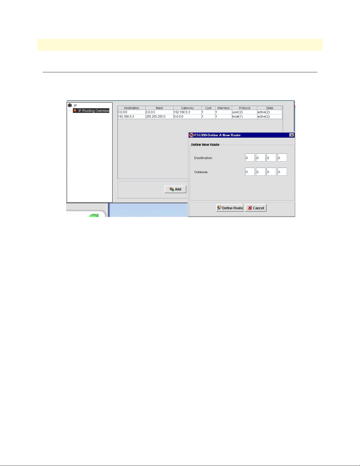
FS6300 NMS Getting Started Guide 7 • Configuring the 6511RC Card
Configuring IP Routing
Click on IP Routing to add routes and view routing information. The IP Overview window shows details for
routing destinations, and includes information for gateway, cost, interface, protocol, and state of each route.
Figure 67. Add a New Route to 6511RC
Add Route
To add an IP route:
1. Click the Add button in the IP Overview window.
2. Enter a destination address for the new route.
3. Enter a gateway address for the new route.
4. Click Define Route.
Configuring IP Routing 84
Page 85

FS6300 NMS Getting Started Guide 7 • Configuring the 6511RC Card
Viewing Events and Alerts
Click on Events and Alerts to view a color-coded chart that shows the amount of alarms and severity of alarms
for the card.
Figure 68. 6511RC Events and Alerts
Exporting/Importing the Configuration
Click on Export/Import Configuration to save or load a configuration file.
Exporting the Configuration
To save the current configuration, click on Export Configuration in the menu tree of the window, then click
Export to save the current configuration to a file.
Figure 69. Export Configuration
Viewing Events and Alerts 85
Page 86

FS6300 NMS Getting Started Guide 7 • Configuring the 6511RC Card
Importing the Configuration
To load a configuration file, click on Import Configuration in the menu tree of the window, then click Browse
to select the configuration file you want to load. Click Import to load the file.
Figure 70. Import Configuration
Exporting/Importing the Configuration 86
Page 87

FS6300 NMS Getting Started Guide 7 • Configuring the 6511RC Card
Viewing the System Log
Click on System Log to view and modify syslog information.
Modify Syslog Configuration
If you only want to view the syslog configuration, click on View SystemLog Configuration in the System Log
window. To configure the syslog information, click on Modify SystemLog Configuration in the menu tree in
the Syslog window.
Figure 71. Modify System Log
Viewing the System Log 87
Page 88

FS6300 NMS Getting Started Guide 7 • Configuring the 6511RC Card
Configuring SDH
Click on SDH Configuration to bring up the SDH Configuration window to view and modify SDH interfaces and paths.
Configuring SDH Interfaces
To configure SDH interfaces:
1. Click on View/Modify SDH Configuration in the menu tree of the SDH Configuration window.
Figure 72. 6511RC SDH Interface Configuration
2. Select a Physical Interface from the drop-down menu under SDH Physical Configuration, and click Sub-
mit. The Physical Interface corresponds to the physical cabling atatched to the STM-1 interface ports.
Select Optical if you are using fiber-optic cable connected to the rear-card SC connectors.
Select Electrical if you are using coaxial cables connected to the rear-card BNC connectors.
3. If desired, enter an alphanumeric name for the STM-1 link in the Circuit Identifier field.
4. If section trace is enabled in your connected SDH network, select sectionTraceEnable from the Section
Trace Monitor drop-down menu. Otherwise, select sectionTraceDisable, and go to Step 8 on page 89.
5. If the Section Trace Monitor is Enabled, enter the alphanumeric name your connected SDH network uses
for the Section Trace message in the SDH frame.
Configuring SDH 88
Page 89

FS6300 NMS Getting Started Guide 7 • Configuring the 6511RC Card
6. Select the message length used by the SDH network –1-byte, 16-byte, or 64-byte– from the Section Trace
Message Len drop-down menu.
7. Enter the value the connetced SDH network uses for the J0 byte in the Section Trace J0 Byte field.
Note J0 Byte only applies to the 1-byte Section Trace Messages. For 16-byte or 64-
byte, the J0 value is ignored and the trace message value applies.
8. If the SDH network transmits a scrambled payload, select Enable from the Tx Payload Scramble drop-
down menu. Otherwise, select Disable.
9. If the SDH network expects to receive a scrambled payload, select Enable from the Rx Payload Scramble
drop-down menu. Otherwise, select Disable.
10. Select a loop type from the Loopback drop-down menu.
11. For SDH Mapping, select the type of AU that corresponds to the SDH multiplexing path you want to
use. Select au4Mapper if you want to multiplex three TUG-3s into an AU-4. Select au3Mapper if you
want to multiplex seven TUG-2s into an AU-3.
12. Click Submit to save your changes.
Configuring SDH Paths
To configure SDH paths:
1. Click on SDH Path Configuration in the menu tree of the SDH Configuration window. Path Trace set-
tings will vary, depending on which type of SDH mapping is being used– AU-3 or AU-4.
Figure 73. 6511RC SDH Path Configuration
2. Select Enable from the Trace Monitor drop-down menu if Path Trace is enabled in the connected SDH
network.
3. Enter the alphanumeric name your SDH network uses for the Path-1 Trace Message in the Trace field.
This only applies to 16-byte and 64-byte section trace messages.
4. Select the message length value your SDH network uses from the Trace Message Len drop-down menu.
5. For Trace J1 Byte, enter the value your connected SDH network uses for the J1 byte in the SDH frame.
J1 only applies to 1-byte trace messages.
Configuring SDH 89
Page 90

FS6300 NMS Getting Started Guide 7 • Configuring the 6511RC Card
6. Enter the Signal Label in the text field.
7. Click Submit.
Configuring SDH Mapper
To configure the SDH Mapper:
1. Click on SDH Mapper Configuration in the menu tree of the SDH Configuration window.
2. Select AsyncE1 or ByteSyncE1 to configure the payload type for the SDH Mapper.
3. Click Submit.
Viewing Alarm Status
To view SDH alarms, click on Alarm Status in the menu tree of the SDH Configuration window. Hover the
mouse pointer over an LED (Section, Line, or Path) to view the alarm status.
Viewing Statistics
To view SDH statistics, click on Near End Statistics or Far End Statistics in the menu tree of the SDH Con-
figuration window. Click on an LED in the Current column to edit the Stats Refresh Rate. Click on an LED in
the History column to view past details.
Viewing E1Link Layers
Click on Display E1 Link VC(#) to show a map of all the E1 links on a TUG. To edit a link, right-click on the
E1 link icon that you want to edit and select E1 Port Link Configuration. (See “Configuring E1 Links” on
page 81).
Figure 74. 6511RC E1 Link Map
Viewing E1Link Layers 90
Page 91

Chapter 8 Configuring Chassis
Chapter contents
Introduction..........................................................................................................................................................92
Chassis Configuration Menu .................................................................................................................................92
Viewing the Chassis LEDs.....................................................................................................................................93
Managing Inband H110 Channels ........................................................................................................................93
Add H110 Management Channel ...................................................................................................................94
Delete H110 Management Channel ...............................................................................................................95
Viewing the Card Layer Map.................................................................................................................................96
91
Page 92

FS6300 NMS Getting Started Guide 8 • Configuring Chassis
Introduction
To configure a chassis, navigate to Network Maps > Geographical Area > Network Node in the menu tree on
the left side of the screen. Right-click on a chassis icon in the main window to display the configuration menu
for the chassis.
Chassis Configuration Menu
The following options are available in the pull-down menu for a chassis:
Figure 75. Chassis Configuration Menu
• Chassis Overview – Shows information for the chassis, including Area ID and Network Node, Chassis ID,
Name, and Type, Network IP, Number of Cards, and Alarm Status
• Chassis Unit GUI – See “Viewing the Chassis LEDs” on page 93
• Chassis Clocking Sync – See “Configuring Card System Clocking” on page 34 in Chapter 3
• Inband H110 Channel Management – See “Managing Inband H110 Channels” on page 93
• Re-Discover All Cards – See “Re-Discovering Cards” on page 27 in Chapter 2
• Display Card Layer – See “Viewing the Card Layer Map” on page 96
• UnManage – See Chapter 9, “Monitoring Managed Objects” on page 97
Introduction 92
Page 93

FS6300 NMS Getting Started Guide 8 • Configuring Chassis
Viewing the Chassis LEDs
Click on Chassis Unit GUI to view the front panels of all of the cards in the chassis in real-time.
Figure 76. Chassis LEDs
Managing Inband H110 Channels
Click on Inband H110 Channel Management to bring up the Channel Management window. To view a list
of existing H110 management channels, click on Defined Channels in the menu tree of the Inband Management window.
Figure 77. Chassis Defined Channels
Viewing the Chassis LEDs 93
Page 94

FS6300 NMS Getting Started Guide 8 • Configuring Chassis
Add H110 Management Channel
To add an H110 management channel to a chassis:
1. Click on Add in the menu tree of the Inband Management window.
Figure 78. Add H110 Management Channel to Chassis
2. Select a Source Card from the drop-down menu.
3. Enter a Channel Name for the Source Card in the text field.
4. Select a Target Card from the drop-down menu.
5. Select a port from the Tx drop-down menu and enter the time slots in the text field for transmitting data.
6. Select a port from the Rx drop-down menu and enter the time slots in the text field for receiving data.
7. Repeat Steps 3-6 for the Target Card.
8. Click Define.
Managing Inband H110 Channels 94
Page 95

FS6300 NMS Getting Started Guide 8 • Configuring Chassis
Delete H110 Management Channel
To delete a H110 management channel from a chassis:
1. Click on Delete in the menu tree of the Inband Management window.
Figure 79. Delete H110 Management Channel from Chassis
2. Select a Source Card from the drop-down menu, and click View.
3. Select the row in the table of the channel you want to delete, and click Edit.
4. The Delete Configuration window displays, which shows the information for the channel.
5. Click Delete.
Managing Inband H110 Channels 95
Page 96

FS6300 NMS Getting Started Guide 8 • Configuring Chassis
Viewing the Card Layer Map
Click on Display Card Layer to view a map of all of the cards in the chassis. Right-click on a card to configure
to view it’s configuration menu.
Figure 80. Chassis Card Layer Map
Viewing the Card Layer Map 96
Page 97

Chapter 9 Monitoring Managed Objects
Chapter contents
Introduction..........................................................................................................................................................98
Working with Managed Objects............................................................................................................................98
Geographical Areas .........................................................................................................................................99
Network Nodes ...............................................................................................................................................99
Chassis ............................................................................................................................................................99
Network Addresses ........................................................................................................................................100
Cards ............................................................................................................................................................100
Interfaces ......................................................................................................................................................100
DSL Ports .....................................................................................................................................................101
IDSL Ports ....................................................................................................................................................101
T1/E1 Ports ..................................................................................................................................................101
E1 Links .......................................................................................................................................................101
Working with Unmanaged Objects .....................................................................................................................102
Managing an Unmanaged Object .................................................................................................................102
97
Page 98

FS6300 NMS Getting Started Guide 9 • Monitoring Managed Objects
Introduction
Managed objects save information about an element in the network database. You can view a list of managed
objects by clicking on Network Database in the menu tree on the left side of the screen, then Managed
Objects.
This chapter describes viewing the various properties of managed objects. It also covers other aspects of the
Network Database section of the NMS interface, such as Unmanaged Objects.
Working with Managed Objects
Click on Network Database > Managed Objects in the main menu tree to view a full list of managed objects
in the network. Right-click on a device in the Managed Objects table to view a device-specific menu for configuring that device. The device-specific menu also appears as a toolbar at the top of the screen when you select a
device in the table. All Managed Objects have the options to UnManage and Update Status.
Figure 81. Managed Objects Table
Expand the Managed Objects selection in the menu tree to view specific object categories.
• “Geographical Areas” (See page 99)
• “Network Nodes” (See page 99)
• “Chassis” (See page 99)
• “Network Addresses” (See page 100)
• “Cards” (See page 100)
• “Interfaces” (See page 100)
• “DSL Ports” (See page 101)
• “IDSL Ports” (See page 101)
• “T1/E1 Ports” (See page 101)
• “E1 Links” (See page 101)
Introduction 98
Page 99

FS6300 NMS Getting Started Guide 9 • Monitoring Managed Objects
Geographical Areas
Navigate to Network Database > Managed Objects > Geographical Areas in the menu tree to view a list of all
managed geographical areas in the network. Select a row and click the new menu in the toolbar at the top of
the screen (or right-click on the row) to view the configuration menu for that geographical area.
The configuration menu for a geographical area has the following options:
• Delete Objects and Traces – See the FS6300 Administrator’s Reference Guide
• Geographical Area Overview – Displays a summary of the area name, ID, number of nodes, # of chassis,
number of subnets, alarm status.
• Re-Discover All Cards – Re-discovers all of the cards in the geographical area. See “Re-Discovering Cards”
on page 27 in Chapter 2.
• UnManage – Moves the area to the UnManaged Objects table.
• Update Status – Refreshes the information for the area.
Network Nodes
Navigate to Network Database > Managed Objects > Network Nodes in the menu tree to view a list of all
managed nodes in the network. Select a row and click the new menu in the toolbar at the top of the screen (or
right-click on the row) to view the configuration menu for that node.
The configuration menu for a network node has the following options:
• Delete Objects and Traces – See the FS6300 Administrator’s Reference Guide
• Alarm Trap Manager – See “Configuring the Alarm Trap Manager” on page 29 in Chapter 3
• Network Node Overview – Displays a summary of the node, including geographical area name and ID,
node name and ID, system manager, and location info.
• Re-Discover All Cards – Re-discovers all of the cards in the network node. See “Re-Discovering Cards” on
page 27 in Chapter 2.
• UnManage – Moves the node to the UnManaged Objects table.
• Update Status – Refreshes the information for the node.
Chassis
Navigate to Network Database > Managed Objects > Chassis in the menu tree to view a list of all managed
chassis in the network. Select a row and click the new menu in the toolbar at the top of the screen (or rightclick on the row) to view the configuration menu for that chassis.
The configuration menu for a chassis has the following options:
• Delete Objects and Traces – See the FS6300 Administrator’s Reference Guide
• Chassis Overview – Displays a summary of the chassis, including geographical area name and ID, node
name and ID, chassis name, ID, and type, network address, number of each card model, and alarm status.
• Chassis Unit GUI – See “Viewing the Chassis LEDs” on page 93 in Chapter 8.
• Chassis Clocking Sync– See “Configuring Card System Clocking” on page 34 in Chapter 3.
• Inband H110 Channel Management – See “Managing Inband H110 Channels” on page 93 in Chapter 8
Working with Managed Objects 99
Page 100

FS6300 NMS Getting Started Guide 9 • Monitoring Managed Objects
• Time Slot Availability in Ports – See “Viewing the Card Layer Map” on page 96 in Chapter 8
• Re-Discover All Cards – Re-discovers the cards in the chassis. See “Re-Discovering Cards” on page 27 in
Chapter 2.
• UnManage – Moves the chassis to the UnManaged Objects table.
• Update Status – Refreshes the information for the chassis.
Network Addresses
Navigate to Network Database > Managed Objects > Network Addresses in the menu tree to view a list of all
managed addresses in the network. Select a row and click the new menu in the toolbar at the top of the screen
(or right-click on the row) to view the configuration menu for that address.
The configuration menu for an address has the following options:
• Delete Objects and Traces – See the FS6300 Administrator’s Reference Guide
• UnManage – Moves the address to the UnManaged Objects table.
• Update Status – Refreshes the information for the network address.
Cards
Navigate to Network Database > Managed Objects > Cards in the menu tree to view a list of all managed
cards in the network. Select a row and click the new menu in the toolbar at the top of the screen (or right-click
on the row) to view the configuration menu for that card. Each card has different configuration options in the
menu, depending on the model of the card you select.
The configuration menu for any card includes the following options:
• Delete Objects and Traces – See the FS6300 Administrator’s Reference Guide
• Card Overview – Displays a summary of the card, including box information, card information, and alarm
status.
• Events and Alerts – See the configuration chapter for the card model.
• Export Import Configuration – See the configuration chapter for the card model.
• Operator Action – See “Managing Operator Actions” on page 40 in Chapter 4.
• System Log – See the configuration chapter for the card model.
• Re-Discover Card – Re-discovers the card in the network. See “Re-Discovering Cards” on page 27 in Chap-
ter 2.
• UnManage – Moves the card to the UnManaged Objects table.
• Update Status – Refreshes the information for the card.
Interfaces
Navigate to Network Database > Managed Objects > Interfaces in the menu tree to view a list of all managed
interfaces in the network. Select a row and click the new menu in the toolbar at the top of the screen (or rightclick on the row) to view the configuration menu for that interface.
Working with Managed Objects 100
 Loading...