


ForeSight 6300
Network Management System
Administrator’s Reference Guide
Sales Office: +1 (301) 975-1000
Technical Support: +1 (301) 975-1007
E-mail: support@patton.com
WWW: www.patton.com
Document Number: 09203U3-001 Rev. A
Part Number: 07MFS6300-ARG
Revised: April 18, 2008

Patton Electronics Company, Inc.
7622 Rickenbacker Drive
Gaithersburg, MD 20879 USA
tel: +1 (301) 975-1000
fax: +1 (301) 869-9293
support: +1 (301) 975-1007
web: www.patton.com
e-mail: support@patton.com
Trademarks
The term ForeSight is a registered trademark of Patton Electronics
Company in the United States and other countries.
Copyright
Copyright © 2008, Patton Electronics Company. All rights reserved.
Notice
The information in this document is subject to change without notice. Patton
Electronics assumes no liability for errors that may appear in this document.
The software described in this document is furnished under a license and may
be used or copied only in accordance with the terms of such license.

Summary Table of Contents
1 Security Management.................................................................................................................................... 12
2 Discovery Management ................................................................................................................................. 27
3 Configuring DS0 Mapping ........................................................................................................................... 40
4 Logs & Reports ............................................................................................................................................. 58
5 Policy Management....................................................................................................................................... 64
6 Contacting Patton for assistance ................................................................................................................... 79
3

Table of Contents
Audience............................................................................................................................................................... 10
Structure............................................................................................................................................................... 10
Viewing Help ....................................................................................................................................................... 11
1 Security Management.................................................................................................................................... 12
Overview ...............................................................................................................................................................13
Managing Users.....................................................................................................................................................13
Adding Users ..................................................................................................................................................13
Modifying User Permissions ...........................................................................................................................16
Disabling Users ...............................................................................................................................................17
Changing User Passwords ...............................................................................................................................18
Deleting Users ................................................................................................................................................18
Assign/Delete Users To/From Groups ............................................................................................................19
Managing Groups..................................................................................................................................................20
Adding Groups ...............................................................................................................................................20
Assign/Delete Users To/From Groups ............................................................................................................21
Deleting Groups .............................................................................................................................................21
Managing Scopes for Groups.................................................................................................................................22
Adding Scopes ................................................................................................................................................22
Deleting Scopes ..............................................................................................................................................23
Managing Operations............................................................................................................................................24
Adding Operations ..........................................................................................................................................24
Deleting Operations ........................................................................................................................................25
Managing Audit Trails ..........................................................................................................................................25
Viewing Audit Trails .......................................................................................................................................25
Searching Audits .............................................................................................................................................26
2 Discovery Management ................................................................................................................................. 27
Overview ...............................................................................................................................................................28
Defining Containers..............................................................................................................................................28
Pre-Defining Containers Before Initial Discovery ...........................................................................................28
Adding Pre-Defined Containers ................................................................................................................28
Modifying Pre-Defined Containers ...........................................................................................................29
Viewing and Deleting Containers ..............................................................................................................31
Defining Containers During Multiple Card Configuration .............................................................................32
Re-Discovering Already Discovered Devices..........................................................................................................34
Setting Discovery Interval......................................................................................................................................35
Configuring Initial Discovery Parameters ..............................................................................................................36
Scheduling Rediscovery .........................................................................................................................................37
Regular Interval ..............................................................................................................................................37
Specific Dates .................................................................................................................................................38
Days of the Week ............................................................................................................................................39
4

5
FS6300 NMS Administrator’s Reference Guide
Table of Contents
3 Configuring DS0 Mapping ........................................................................................................................... 40
Introduction..........................................................................................................................................................41
Map Types in the FS6300 ...............................................................................................................................41
Auto-Screening DS0 Maps ....................................................................................................................................42
Managing Miscellaneous Maps..............................................................................................................................44
Out-of-Range Maps ........................................................................................................................................44
Overlapped Maps ............................................................................................................................................44
Creating Maps.......................................................................................................................................................46
Creating Same Card Maps ..............................................................................................................................46
Creating Inter Card Maps ...............................................................................................................................47
Reserving E1 Pools ..........................................................................................................................................48
Creating Inter Chassis Maps ...........................................................................................................................50
Managing Defined Maps .......................................................................................................................................51
Viewing or Deleting Defined Maps .................................................................................................................51
Managing H.110 Slots...........................................................................................................................................52
Reserving H.110 Slots for 6081 Cards ............................................................................................................52
Viewing H.110 Time Slot Utilization .............................................................................................................54
Viewing H.110 Time Slots through H.110 SlotView ................................................................................54
Viewing H.110 Time Slots through H.110 Port Utilization ......................................................................54
Viewing TDM Port Time Slots .............................................................................................................................56
Viewing DS0 Availability on Ports ........................................................................................................................57
4 Logs & Reports ............................................................................................................................................. 58
Overview ...............................................................................................................................................................59
Managing Logs......................................................................................................................................................59
Saving Log Files ..............................................................................................................................................59
Clearing the Log .............................................................................................................................................59
Managing Reports .................................................................................................................................................60
Alarm Tracking ...............................................................................................................................................60
Chassis Checklist ............................................................................................................................................61
Discovery Checklist ........................................................................................................................................61
Device Checklist .............................................................................................................................................62
NMS Network Summary ................................................................................................................................63
5 Policy Management....................................................................................................................................... 64
Overview ...............................................................................................................................................................65
Adding Policies......................................................................................................................................................66
Table Cleanup Policy ......................................................................................................................................67
6300 NMS Backup Policy ..............................................................................................................................68
Scheduling Backup ....................................................................................................................................68
Alert Delete Policy ..........................................................................................................................................69
Alert Action Policy ..........................................................................................................................................70
Action Types .............................................................................................................................................71
Modifying Policies.................................................................................................................................................78
Deleting Policies....................................................................................................................................................78

6
FS6300 NMS Administrator’s Reference Guide
Table of Contents
Executing Policies..................................................................................................................................................78
Stopping Policies ...................................................................................................................................................78
6 Contacting Patton for assistance ................................................................................................................... 79
Introduction..........................................................................................................................................................80
Contact information..............................................................................................................................................80
Warranty Service and Returned Merchandise Authorizations (RMAs)...................................................................80
Warranty coverage ..........................................................................................................................................80
Out-of-warranty service .............................................................................................................................80
Returns for credit ......................................................................................................................................80
Return for credit policy .............................................................................................................................81
RMA numbers ................................................................................................................................................81
Shipping instructions ................................................................................................................................81

List of Figures
1 Tools > Security Administration . . . . . . . . . . . . . . . . . . . . . . . . . . . . . . . . . . . . . . . . . . . . . . . . . . . . . . . . . . . . 13
2 Add User from Security Window . . . . . . . . . . . . . . . . . . . . . . . . . . . . . . . . . . . . . . . . . . . . . . . . . . . . . . . . . . . 13
3 Add New User . . . . . . . . . . . . . . . . . . . . . . . . . . . . . . . . . . . . . . . . . . . . . . . . . . . . . . . . . . . . . . . . . . . . . . . . . 14
4 User Account Expiry Options . . . . . . . . . . . . . . . . . . . . . . . . . . . . . . . . . . . . . . . . . . . . . . . . . . . . . . . . . . . . . . 14
5 Adding a New User to a Group . . . . . . . . . . . . . . . . . . . . . . . . . . . . . . . . . . . . . . . . . . . . . . . . . . . . . . . . . . . . 15
6 Modify User Permissions . . . . . . . . . . . . . . . . . . . . . . . . . . . . . . . . . . . . . . . . . . . . . . . . . . . . . . . . . . . . . . . . . 16
7 Disable User . . . . . . . . . . . . . . . . . . . . . . . . . . . . . . . . . . . . . . . . . . . . . . . . . . . . . . . . . . . . . . . . . . . . . . . . . . . 17
8 Delete User . . . . . . . . . . . . . . . . . . . . . . . . . . . . . . . . . . . . . . . . . . . . . . . . . . . . . . . . . . . . . . . . . . . . . . . . . . . . 18
9 Assign User to Groups . . . . . . . . . . . . . . . . . . . . . . . . . . . . . . . . . . . . . . . . . . . . . . . . . . . . . . . . . . . . . . . . . . . 19
10 Add New Group . . . . . . . . . . . . . . . . . . . . . . . . . . . . . . . . . . . . . . . . . . . . . . . . . . . . . . . . . . . . . . . . . . . . . . . . 20
11 Assign Users to Groups . . . . . . . . . . . . . . . . . . . . . . . . . . . . . . . . . . . . . . . . . . . . . . . . . . . . . . . . . . . . . . . . . . . 21
12 Add Scope to Group . . . . . . . . . . . . . . . . . . . . . . . . . . . . . . . . . . . . . . . . . . . . . . . . . . . . . . . . . . . . . . . . . . . . . 22
13 Scope Settings . . . . . . . . . . . . . . . . . . . . . . . . . . . . . . . . . . . . . . . . . . . . . . . . . . . . . . . . . . . . . . . . . . . . . . . . . . 22
14 Delete Scope . . . . . . . . . . . . . . . . . . . . . . . . . . . . . . . . . . . . . . . . . . . . . . . . . . . . . . . . . . . . . . . . . . . . . . . . . . . 23
15 Add Operation . . . . . . . . . . . . . . . . . . . . . . . . . . . . . . . . . . . . . . . . . . . . . . . . . . . . . . . . . . . . . . . . . . . . . . . . . 24
16 Search Audits . . . . . . . . . . . . . . . . . . . . . . . . . . . . . . . . . . . . . . . . . . . . . . . . . . . . . . . . . . . . . . . . . . . . . . . . . . 26
17 Tools > Discovery Administration . . . . . . . . . . . . . . . . . . . . . . . . . . . . . . . . . . . . . . . . . . . . . . . . . . . . . . . . . . 28
18 SetUp(F) > 6300 Container Definition . . . . . . . . . . . . . . . . . . . . . . . . . . . . . . . . . . . . . . . . . . . . . . . . . . . . . . . 28
19 Add Container . . . . . . . . . . . . . . . . . . . . . . . . . . . . . . . . . . . . . . . . . . . . . . . . . . . . . . . . . . . . . . . . . . . . . . . . . 29
20 Modify Container . . . . . . . . . . . . . . . . . . . . . . . . . . . . . . . . . . . . . . . . . . . . . . . . . . . . . . . . . . . . . . . . . . . . . . . 30
21 View Containers . . . . . . . . . . . . . . . . . . . . . . . . . . . . . . . . . . . . . . . . . . . . . . . . . . . . . . . . . . . . . . . . . . . . . . . . 31
22 Tools > Multiple Card Configuration . . . . . . . . . . . . . . . . . . . . . . . . . . . . . . . . . . . . . . . . . . . . . . . . . . . . . . . . 32
23 Multiple Card Configuration > Card Parameters . . . . . . . . . . . . . . . . . . . . . . . . . . . . . . . . . . . . . . . . . . . . . . . 32
24 Re-Discover Already Discovered . . . . . . . . . . . . . . . . . . . . . . . . . . . . . . . . . . . . . . . . . . . . . . . . . . . . . . . . . . . . 34
25 Set Discovery Interval . . . . . . . . . . . . . . . . . . . . . . . . . . . . . . . . . . . . . . . . . . . . . . . . . . . . . . . . . . . . . . . . . . . . 35
26 Set Initial Parameters . . . . . . . . . . . . . . . . . . . . . . . . . . . . . . . . . . . . . . . . . . . . . . . . . . . . . . . . . . . . . . . . . . . . 36
27 Schedule Re-Discovery for Regular Intervals . . . . . . . . . . . . . . . . . . . . . . . . . . . . . . . . . . . . . . . . . . . . . . . . . . . 37
28 Schedule Re-Discovery for Specific Dates . . . . . . . . . . . . . . . . . . . . . . . . . . . . . . . . . . . . . . . . . . . . . . . . . . . . . 38
29 Schedule Re-Discovery for Days of the Week . . . . . . . . . . . . . . . . . . . . . . . . . . . . . . . . . . . . . . . . . . . . . . . . . . 39
30 Auto-Screening window . . . . . . . . . . . . . . . . . . . . . . . . . . . . . . . . . . . . . . . . . . . . . . . . . . . . . . . . . . . . . . . . . . 42
31 Miscellaneous Maps window . . . . . . . . . . . . . . . . . . . . . . . . . . . . . . . . . . . . . . . . . . . . . . . . . . . . . . . . . . . . . . 44
32 Same Card window . . . . . . . . . . . . . . . . . . . . . . . . . . . . . . . . . . . . . . . . . . . . . . . . . . . . . . . . . . . . . . . . . . . . . . 46
33 Inter Card window . . . . . . . . . . . . . . . . . . . . . . . . . . . . . . . . . . . . . . . . . . . . . . . . . . . . . . . . . . . . . . . . . . . . . . 47
34 Reserve E1 Pools window . . . . . . . . . . . . . . . . . . . . . . . . . . . . . . . . . . . . . . . . . . . . . . . . . . . . . . . . . . . . . . . . . 48
35 Inter Chassis > Create Maps window . . . . . . . . . . . . . . . . . . . . . . . . . . . . . . . . . . . . . . . . . . . . . . . . . . . . . . . . 50
36 View Maps . . . . . . . . . . . . . . . . . . . . . . . . . . . . . . . . . . . . . . . . . . . . . . . . . . . . . . . . . . . . . . . . . . . . . . . . . . . . 51
37 Reserve H.110 Slots for 6081 . . . . . . . . . . . . . . . . . . . . . . . . . . . . . . . . . . . . . . . . . . . . . . . . . . . . . . . . . . . . . . 52
38 H.110 SlotView . . . . . . . . . . . . . . . . . . . . . . . . . . . . . . . . . . . . . . . . . . . . . . . . . . . . . . . . . . . . . . . . . . . . . . . . 54
39 H.110 Port Utilization . . . . . . . . . . . . . . . . . . . . . . . . . . . . . . . . . . . . . . . . . . . . . . . . . . . . . . . . . . . . . . . . . . . 55
40 TDM Port Utilization . . . . . . . . . . . . . . . . . . . . . . . . . . . . . . . . . . . . . . . . . . . . . . . . . . . . . . . . . . . . . . . . . . . 56
41 DS0 Availability by Ports . . . . . . . . . . . . . . . . . . . . . . . . . . . . . . . . . . . . . . . . . . . . . . . . . . . . . . . . . . . . . . . . . 57
42 Time Slot Details . . . . . . . . . . . . . . . . . . . . . . . . . . . . . . . . . . . . . . . . . . . . . . . . . . . . . . . . . . . . . . . . . . . . . . . 57
43 Logs window . . . . . . . . . . . . . . . . . . . . . . . . . . . . . . . . . . . . . . . . . . . . . . . . . . . . . . . . . . . . . . . . . . . . . . . . . . 59
44 Save Log File . . . . . . . . . . . . . . . . . . . . . . . . . . . . . . . . . . . . . . . . . . . . . . . . . . . . . . . . . . . . . . . . . . . . . . . . . . . 59
45 Reports Menu . . . . . . . . . . . . . . . . . . . . . . . . . . . . . . . . . . . . . . . . . . . . . . . . . . . . . . . . . . . . . . . . . . . . . . . . . . 60
46 Alarm Tracking Report . . . . . . . . . . . . . . . . . . . . . . . . . . . . . . . . . . . . . . . . . . . . . . . . . . . . . . . . . . . . . . . . . . . 60
47 Chassis Checklist . . . . . . . . . . . . . . . . . . . . . . . . . . . . . . . . . . . . . . . . . . . . . . . . . . . . . . . . . . . . . . . . . . . . . . . 61
7

8
3224/6081RC Administrator’s Reference Guide
48 Discovery Checklist . . . . . . . . . . . . . . . . . . . . . . . . . . . . . . . . . . . . . . . . . . . . . . . . . . . . . . . . . . . . . . . . . . . . . 61
49 Device Checklist . . . . . . . . . . . . . . . . . . . . . . . . . . . . . . . . . . . . . . . . . . . . . . . . . . . . . . . . . . . . . . . . . . . . . . . . 62
50 NMS Network Summary Window . . . . . . . . . . . . . . . . . . . . . . . . . . . . . . . . . . . . . . . . . . . . . . . . . . . . . . . . . . 63
51 Policy Menu . . . . . . . . . . . . . . . . . . . . . . . . . . . . . . . . . . . . . . . . . . . . . . . . . . . . . . . . . . . . . . . . . . . . . . . . . . . 65
52 Policy drop-down menu . . . . . . . . . . . . . . . . . . . . . . . . . . . . . . . . . . . . . . . . . . . . . . . . . . . . . . . . . . . . . . . . . . 66
53 Adding Table Cleanup Policy . . . . . . . . . . . . . . . . . . . . . . . . . . . . . . . . . . . . . . . . . . . . . . . . . . . . . . . . . . . . . . 67
54 Adding NMS Backup Policy . . . . . . . . . . . . . . . . . . . . . . . . . . . . . . . . . . . . . . . . . . . . . . . . . . . . . . . . . . . . . . . 68
55 Policy Scheduler . . . . . . . . . . . . . . . . . . . . . . . . . . . . . . . . . . . . . . . . . . . . . . . . . . . . . . . . . . . . . . . . . . . . . . . . 68
56 Adding Alert Delete Policy . . . . . . . . . . . . . . . . . . . . . . . . . . . . . . . . . . . . . . . . . . . . . . . . . . . . . . . . . . . . . . . . 69
57 Adding Alert Action Policy . . . . . . . . . . . . . . . . . . . . . . . . . . . . . . . . . . . . . . . . . . . . . . . . . . . . . . . . . . . . . . . . 70
58 Suppress Action . . . . . . . . . . . . . . . . . . . . . . . . . . . . . . . . . . . . . . . . . . . . . . . . . . . . . . . . . . . . . . . . . . . . . . . . 72
59 Send Trap Action . . . . . . . . . . . . . . . . . . . . . . . . . . . . . . . . . . . . . . . . . . . . . . . . . . . . . . . . . . . . . . . . . . . . . . . 73
60 Send E-mail Action . . . . . . . . . . . . . . . . . . . . . . . . . . . . . . . . . . . . . . . . . . . . . . . . . . . . . . . . . . . . . . . . . . . . . . 74
61 Add Custom Filter . . . . . . . . . . . . . . . . . . . . . . . . . . . . . . . . . . . . . . . . . . . . . . . . . . . . . . . . . . . . . . . . . . . . . . 75
62 Run Command Action . . . . . . . . . . . . . . . . . . . . . . . . . . . . . . . . . . . . . . . . . . . . . . . . . . . . . . . . . . . . . . . . . . . 76
63 Set Severity . . . . . . . . . . . . . . . . . . . . . . . . . . . . . . . . . . . . . . . . . . . . . . . . . . . . . . . . . . . . . . . . . . . . . . . . . . . . 77

List of Tables
1 Table Cleanup Policy Properties . . . . . . . . . . . . . . . . . . . . . . . . . . . . . . . . . . . . . . . . . . . . . . . . . . . . . . . . . . . . 67
2 FS6300 NMS Backup Policy Properties . . . . . . . . . . . . . . . . . . . . . . . . . . . . . . . . . . . . . . . . . . . . . . . . . . . . . . 68
3 Alert Delete Policy Properties . . . . . . . . . . . . . . . . . . . . . . . . . . . . . . . . . . . . . . . . . . . . . . . . . . . . . . . . . . . . . . 69
4 Alert Action Policy Properties . . . . . . . . . . . . . . . . . . . . . . . . . . . . . . . . . . . . . . . . . . . . . . . . . . . . . . . . . . . . . . 70
9

About this guide
For getting started information, refer to the FS6300 NMS Getting Started Guide .
Audience
This guide is intended for the following users:
• Operators
• Installers
• Maintenance technicians
Structure
This guide contains the following chapters and appendices:
• Chapter 1 on page 12 provides information on managing security
• Chapter 2 on page 27 provides information on managing discovery tools
• Chapter 3 on page 40 provides information on configuring DS0 mapping
• Chapter 4 on page 58 provides information on creating and saving logs and reports
• Chapter 5 on page 64 provides information on adding and managing automatic policies
• Chapter 6 on page 79 provides information on contacting Patton for support
10

1.
1.
About this guide
FS6300 NMS Administrator’s Reference Guide
Viewing Help
To view FS6300 NMS Help:
From Help menu, choose Help Contents . An HTML file with links to all FS6300 NMS documents is displayed in a Web browser (the default browser that has been configured in your system).
To view context-sensitive help in Application Client, do any of the following:
Context-sensitive help displays appropriate Help topic which assists you to get specific information about
whatever part of the client you are using at any given moment.
• Press F1 on any dialog box or window (or)
• Click the Help button on the toolbar in a window.
A help file associated with the screen you are working on is displayed.
To view context-sensitive help in Application Client dialog boxes:
Click the Help button.
11

Chapter 1
Chapter contents
Overview ...............................................................................................................................................................13
Managing Users.....................................................................................................................................................13
Adding Users ..................................................................................................................................................13
Modifying User Permissions ...........................................................................................................................16
Disabling Users ...............................................................................................................................................17
Changing User Passwords ...............................................................................................................................18
Deleting Users ................................................................................................................................................18
Assign/Delete Users To/From Groups ............................................................................................................19
Managing Groups..................................................................................................................................................20
Adding Groups ...............................................................................................................................................20
Assign/Delete Users To/From Groups ............................................................................................................21
Deleting Groups .............................................................................................................................................21
Managing Scopes for Groups.................................................................................................................................22
Adding Scopes ................................................................................................................................................22
Deleting Scopes ..............................................................................................................................................23
Managing Operations............................................................................................................................................24
Adding Operations ..........................................................................................................................................24
Deleting Operations ........................................................................................................................................25
Managing Audit Trails ..........................................................................................................................................25
Viewing Audit Trails .......................................................................................................................................25
Searching Audits .............................................................................................................................................26
Security Management
12

13
1.
FS6300 NMS Administrator’s Reference Guide
1 • Security Management
Overview
The Security Administration window is an important tool for managing users and groups, and for managing
their permissions and actions in the FS6300 NMS. To reach the Security Administration window, click on
Tools > Security Administration at the top of the screen.
Figure 1. Tools > Security Administration
Managing Users
Before anyone has access to the FS6300 NMS Client, he or she must be added as a user to the FS6300 NMS
Server database. After you have created users, you can add them to groups, and give them specific permissions.
Adding Users
To add a new user:
In the Security Administration window, do any of the following:
Figure 2. Add User from Security Window
– From the File menu, choose New > AddUser.
– Press Ctrl+Shift+U .
– Click the Add User icon .
The User Administration window displays.
Overview
14
2.
3.
FS6300 NMS Administrator’s Reference Guide
1 • Security Management
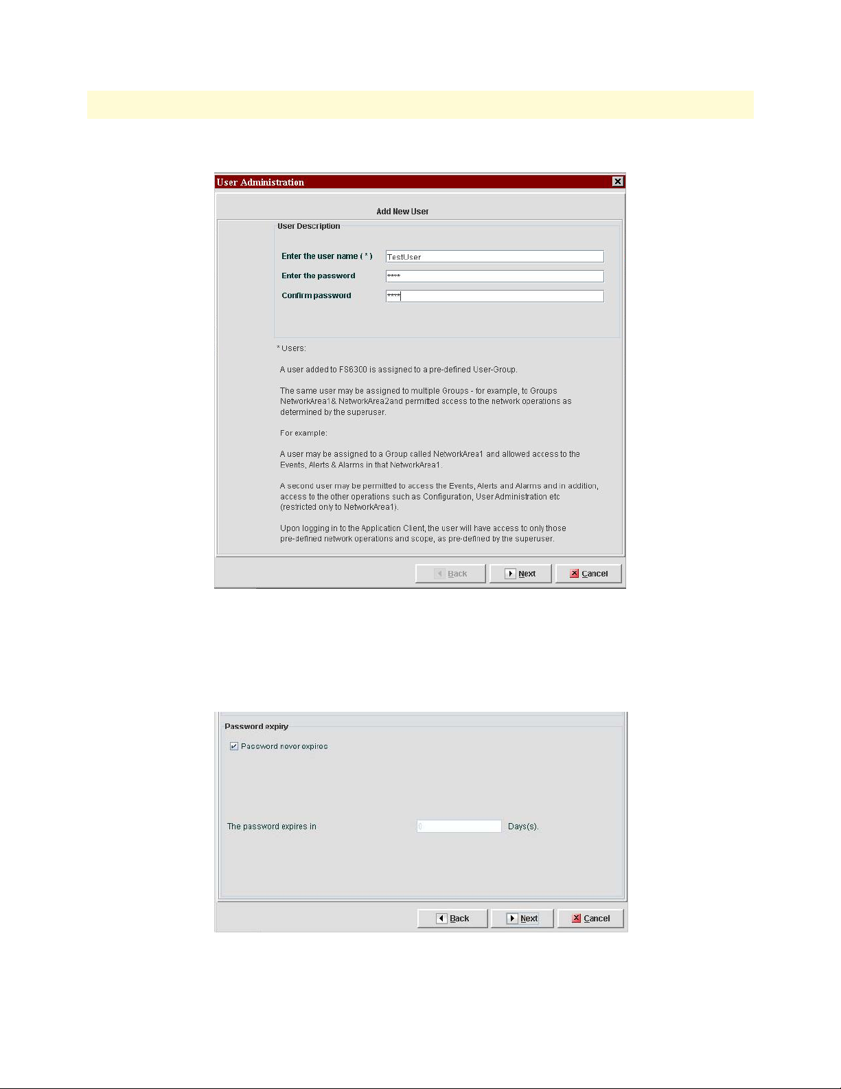
Figure 3. Add New User
Type the desired user name and password in the text fields and click Next .
If desired, you can set the account and/or password to expire after a certain amount of time. By default, the
user account and password are set to never expire. Make the desired changes, then click Next.
Figure 4. User Account Expiry Options
Managing Users
15
4.
5.
FS6300 NMS Administrator’s Reference Guide
1 • Security Management
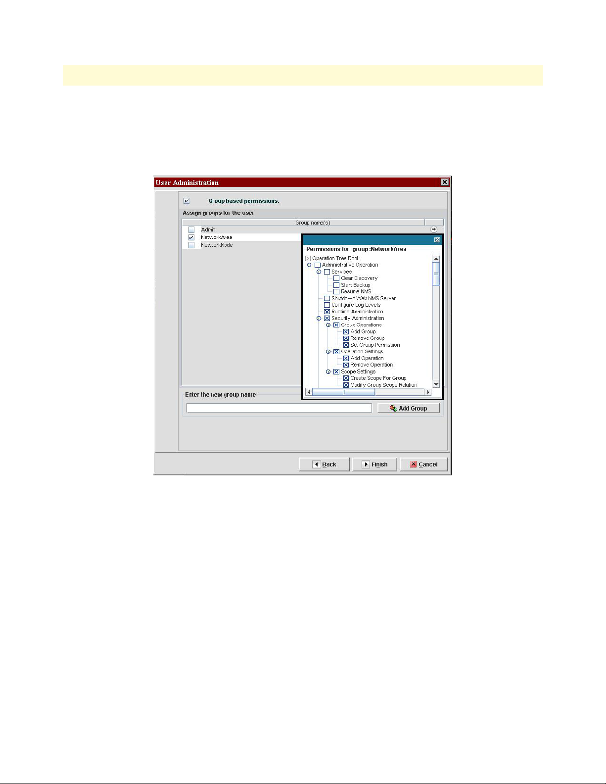
If you are associating the user to have permissions based on an existing group, select the Group-based per-
missions checkbox. Then, select the checkbox of the group that you want to add the new user to. Click on
the arrow on the right side of the Group Names table to view permissions for a group.
If you want to create a new group while adding a new user, type in a name for the new group, then click
Add Group . For details about managing group permissions, see “Managing Groups” on page 20).
Figure 5. Adding a New User to a Group
If you did not select the checkbox for group-based permissions and want to set the user’s permissions individually, click Finish , and see “Modifying User Permissions” on page 16.
Click Finish . The new user is displayed in the Security window menu tree under Users.
Managing Users
16
1.
2.
3.
FS6300 NMS Administrator’s Reference Guide
1 • Security Management
Modifying User Permissions
To add, delete, or modify permissions for an individual user:
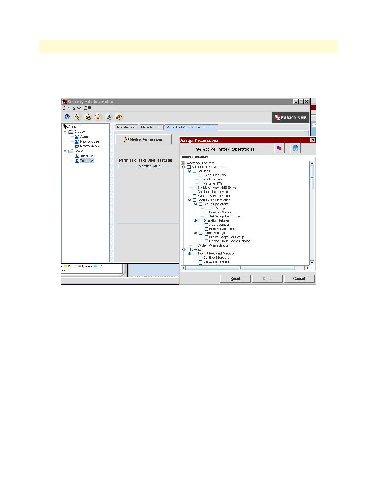
In the Security Administration window, click on the user in the User section of the menu tree.
Figure 6. Modify User Permissions
Click on the Permitted Operations for User tab, then click on the Modify Permissions button.
In the Assign Permissions window, select the checkboxes of the allowed operations for the user. Then,
click Done.
4. The permissions for the user are displayed in a table in the Permitted Operations for User tab. If desired,
you may add a note for allowed operations. To ad a note, double-click on the Description column in the
user’s Permissions table.
Managing Users
FS6300 NMS Administrator’s Reference Guide 1 • Security Management
Disabling Users
To temporarily disable a user from logging in and accessing the NMS:
1. In the Security Administration window, click on the user in the User section of the menu tree.
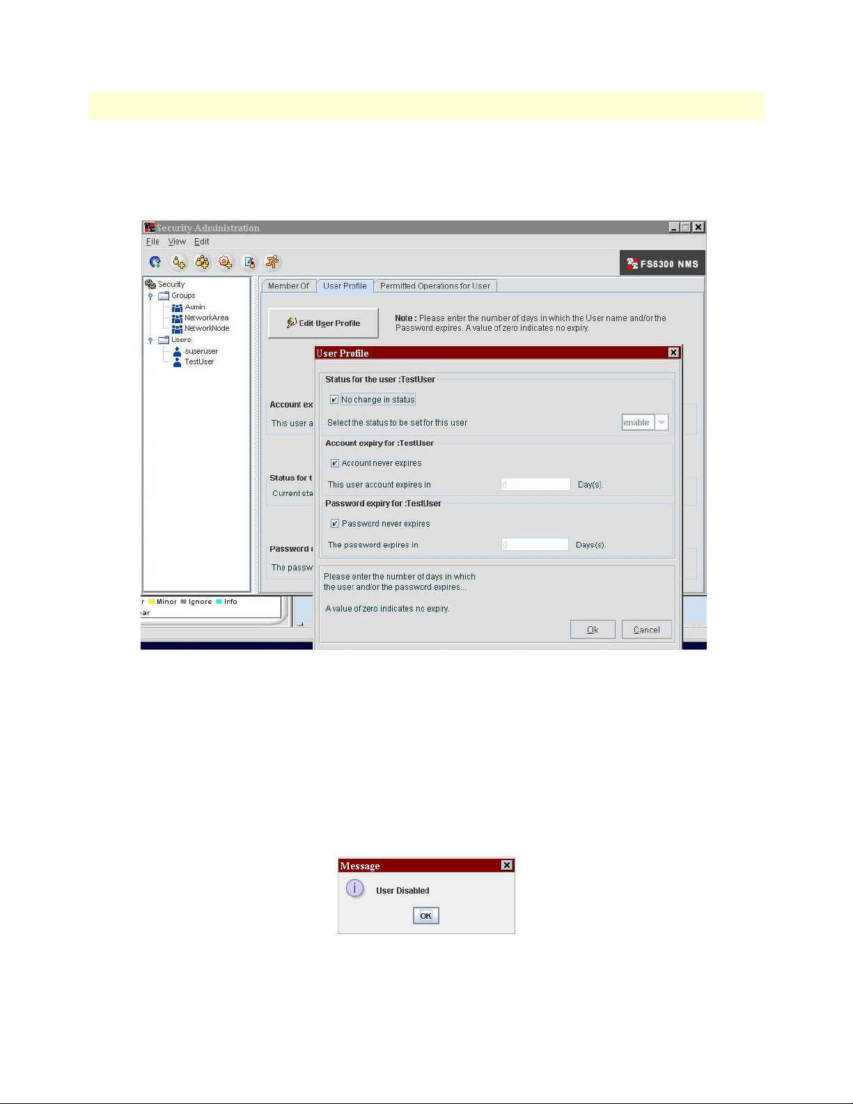
Figure 7. Disable User
2. Click on the User Profile tab, then click on the Edit User Profile button.
3. In the User Profile window, you can edit the status of the user, and when the user account and/or password
expires.
4. To temporarily disable a user, de-select the No change in status checkbox, then choose disable from the
status drop-down menu.
5. Click OK. A red circle with a white “x” will appear on the user’s name in the Security window menu tree.
When the user attempts to log in to the NMS, a message will display–”User Disabled.”
6. To re-enable a disabled user’s account, repeat steps 1-4, except select enable from the status drop-down
menu. Click OK.
Managing Users 17
FS6300 NMS Administrator’s Reference Guide 1 • Security Management
Changing User Passwords
To change a user password:
1. In the Security Administration window, select the user in the menu tree. Then, do any of the following:
– From the Edit menu, choose Change Password.
– Press Ctrl+Shift+C.
– Right-click on the user in the menu tree and select Change Password.
2. In the Change Password dialog box, type in the new password for the user. Then, type in the new pass-
word again.
3. Click OK.
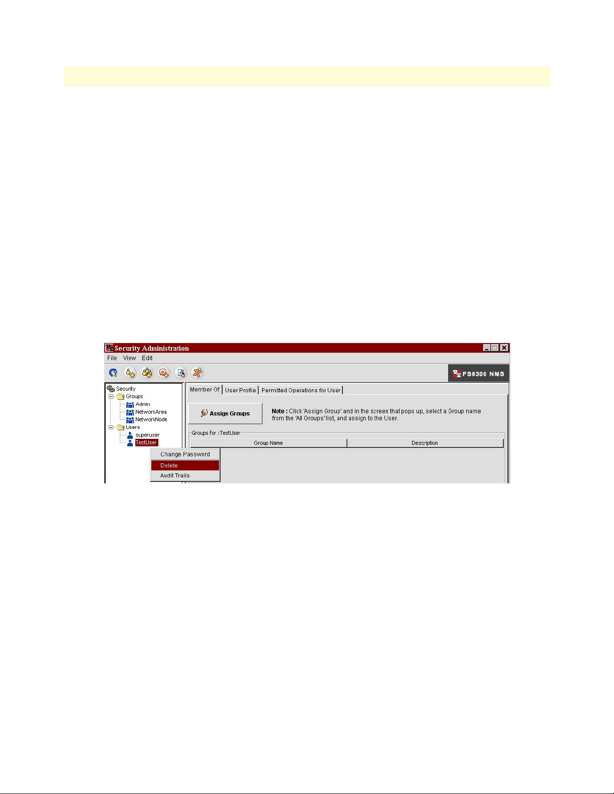
Deleting Users
To delete a user:
1. In the Security Administration window, select the user in the menu tree.
2. Right-click on the user in the menu tree, and select Delete.
Figure 8. Delete User
3. A warning message will display. Click Yes.
Managing Users 18
FS6300 NMS Administrator’s Reference Guide 1 • Security Management
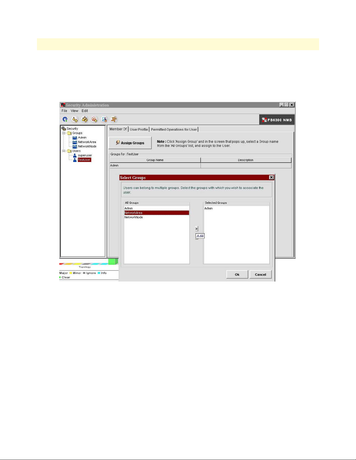
Assign/Delete Users To/From Groups
To assign or delete a user to/from a group:
1. In the Security Administration window, select the user in the menu tree.
2. Click on the Member Of tab, and click the Assign Groups button.
Figure 9. Assign User to Groups
3. In the Select Groups window, click on the group in the All Groups column, then click the “>” button to
add the group to the user’s list. Repeat this step if you want to add the user to multiple groups.
4. To remove a user from a group, click on the group in the Selected Groups column and click the “<“ but-
ton.
5. Click OK.
Note If you remove an Admin user from a group with administrative privi-
leges, this will disallow some permissions for the user. To view/modify
selected user permissions, click on the Permitted Operations for User
tab, then click the Modify Permissions button. The included and
excluded permissions are also listed in the Permissions for User table.
Managing Users 19
FS6300 NMS Administrator’s Reference Guide 1 • Security Management
Managing Groups
In the FS6300 NMS, you can create groups with specific permissions for each group, and then assign users to
these groups with specified operational tasks and permissions.
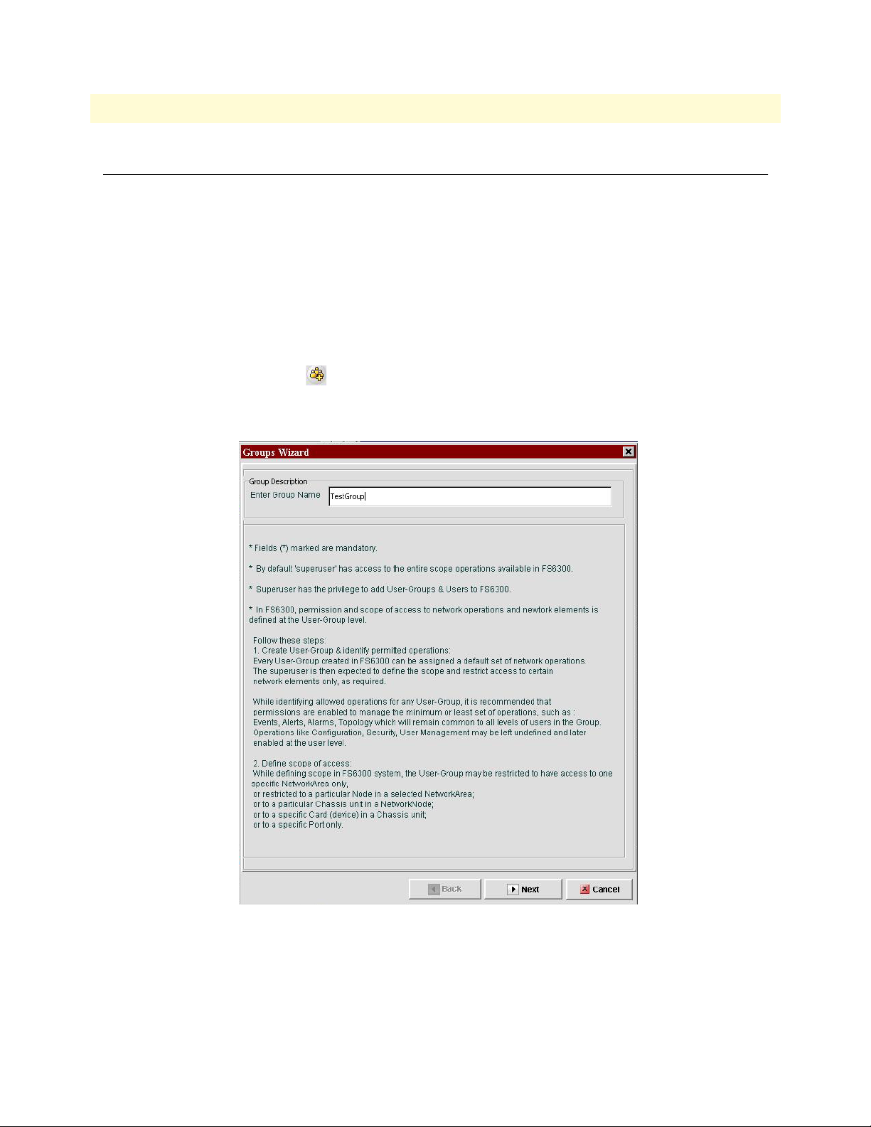
Adding Groups
To add a group:
1. In the Security Administration window, do any of the following:
– From the File menu, choose New > Add Group.
– Press Ctrl+Shift+G.
– Click the Add Group icon .
The Group Wizard window displays.
Figure 10. Add New Group
2. Type the desired group name in the text field and click Next.
3. Select the check boxes for the operations that users in the group will be allowed to do. Click Finish.
Managing Groups 20
FS6300 NMS Administrator’s Reference Guide 1 • Security Management
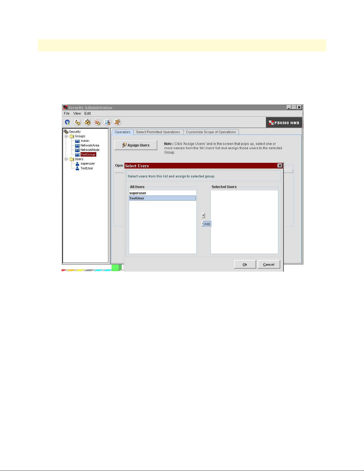
Assign/Delete Users To/From Groups
To assign or delete a user to/from a group:
1. In the Security Administration window, select the group in the menu tree.
2. Click on the Operators tab, and click the Assign Users button.
Figure 11. Assign Users to Groups
3. In the Select Users window, click on the user in the All Users column, then click the “>” button to add the
user to the group’s list. Repeat this step if you want to add multiple users to the group.
4. To remove a user from a group, click on the user in the Selected Users column and click the “<“ button.
5. Click OK.
Deleting Groups
To delete a group:
1. In the Security Administration window, select the group in the menu tree.
2. Right-click on the group in the menu tree, and select Delete.
3. A warning message will display. Click Yes.
Managing Groups 21
FS6300 NMS Administrator’s Reference Guide 1 • Security Management
Managing Scopes for Groups
Scopes are associated with the actual operations of a group and with specific properties to which the users have
access. Scopes are used to set limits to a permission by applying one or more properties to a group permission.
Adding Scopes
To add a scope:
1. In the Security Administration window, select the group in the menu tree.
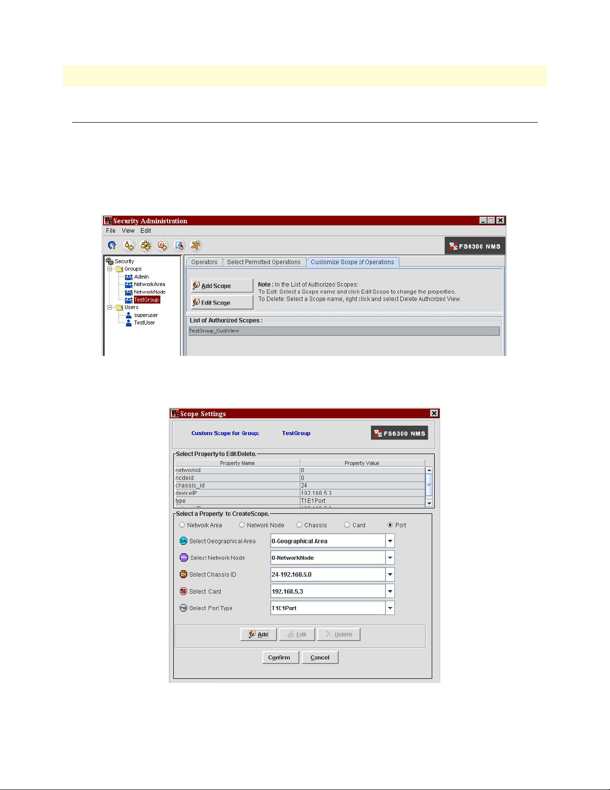
Figure 12. Add Scope to Group
2. Click on the Customize Scope of Operations tab, and click the Add Scope button.
Figure 13. Scope Settings
Managing Scopes for Groups 22
FS6300 NMS Administrator’s Reference Guide 1 • Security Management
3. Select the property that you would like to add for the group. You can select from Geographical Area, Network Node, Chassis, Card, and Port.
4. Click the Add button. The Property value will appear in the table in the Scope Settings window.
5. Click the Confirm button to add the scope.
Deleting Scopes
To delete a scope:
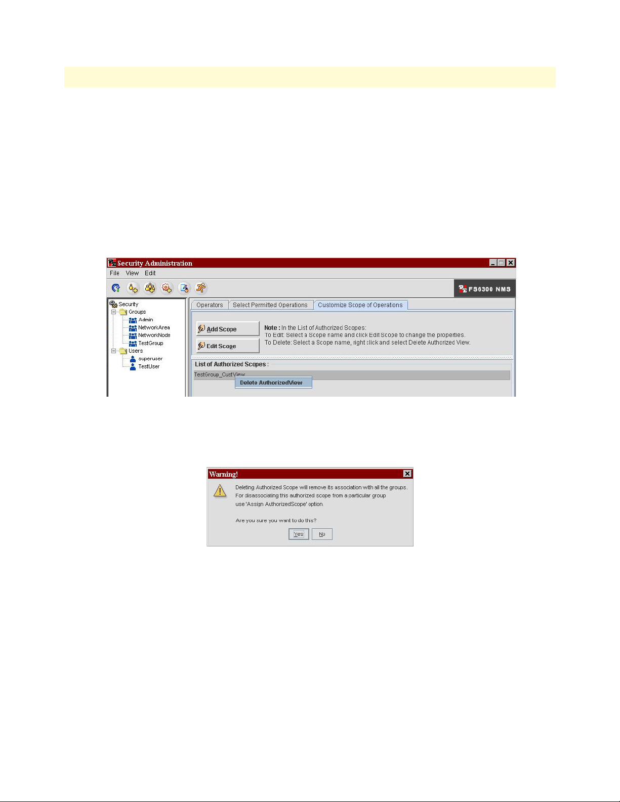
1. In the Security Administration window, select the group in the menu tree.
2. Click on the Customize Scope of Operations tab.
Figure 14. Delete Scope
3. Right-click on the scope in the List of Authorized Scopes table, and select Delete AuthorizedView.
4. A warning message will display. Click Yes.
Managing Scopes for Groups 23
FS6300 NMS Administrator’s Reference Guide 1 • Security Management
Managing Operations
The Operations Tree contains a list of operations (also referred to as permissions) that is provided by default in
FS6300 NMS. The operations are logically arranged in a tree structure with parent and child operations. You
can add new operations when they are needed and delete obsolete operations.
Adding Operations
To add new operations to the operations tree so that users/groups can add it to their permissions:
1. In the Security Administration window, do any of the following:
– From the File menu, choose New > Add Operations.
– Press Ctrl+Shift+O.
– Click the Add Operation icon .
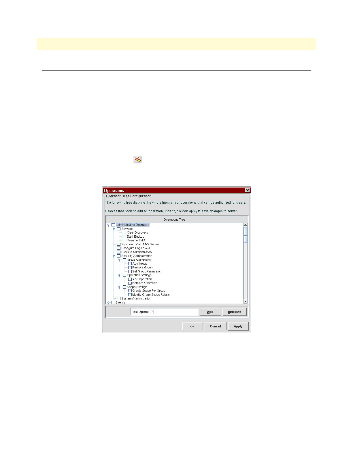
2. In the Operations window, select the top of the operation group in the tree where you want to add the
new operation.
Figure 15. Add Operation
3. Type in the name of the new operation in the text field and click Add.
4. Click Apply.
5. Repeat steps 2-4 to add more new operations. Then, click OK.
Managing Operations 24

FS6300 NMS Administrator’s Reference Guide 1 • Security Management
Deleting Operations
To delete operations in the operations tree:
1. In the Security Administration window, press Ctrl+Shift+O to open the Operations list.
2. In the Operations window, select the operation in the tree that you want to delete.
3. Click Remove.
4. A warning message will display. Click Yes.
5. Click OK.
Managing Audit Trails
Audit trails allow you to view the operations that have been performed by a user. The audit trail identifies all
operations that have been performed, the time, whether it was successful, category, and audited object. You
should periodically clear the trails after they have been reviewed.
Viewing Audit Trails
To view audit trails:
1. In the Security Administration window, do any of the following:
– From the View menu, click Audit Trails.
– Press Ctrl+Shift+A.
– Click the Audit Trails icon .
The Auth Audit Screen displays.
2. To view details of a specific audit, select the operation in the Auth Audit table, then click View > Audit
Details at the top of the window.
3. Click the Clear Audits button at the bottom of the window to delete all of the audits in the table.
Managing Audit Trails 25

FS6300 NMS Administrator’s Reference Guide 1 • Security Management
Searching Audits
To search for audits matching certain criteria:
1. In the Security Administration window, do any of the following:
– From the View menu, click Audit Trails.
– Press Ctrl+Shift+A.
– Click the Audit Trails icon .
The Auth Audit Screen displays.
2. Select Edit > Search (or Ctrl+F) from the top of the screen. The Search box displays.
Figure 16. Search Audits
3. Select and enter your search criteria and click the Search button. You can search the audits by User, Oper-
ation, Time, Status, Category, or Object.
Managing Audit Trails 26

Chapter 2 Discovery Management
Chapter contents
Overview ...............................................................................................................................................................28
Defining Containers..............................................................................................................................................28
Pre-Defining Containers Before Initial Discovery ...........................................................................................28
Adding Pre-Defined Containers ................................................................................................................28
Modifying Pre-Defined Containers ...........................................................................................................29
Viewing and Deleting Containers ..............................................................................................................31
Defining Containers During Multiple Card Configuration .............................................................................32
Re-Discovering Already Discovered Devices..........................................................................................................34
Setting Discovery Interval......................................................................................................................................35
Configuring Initial Discovery Parameters ..............................................................................................................36
Scheduling Rediscovery .........................................................................................................................................37
Regular Interval ..............................................................................................................................................37
Specific Dates .................................................................................................................................................38
Days of the Week ............................................................................................................................................39
27

FS6300 NMS Administrator’s Reference Guide 2 • Discovery Management
Overview
The Discovery process is the most important step in working with the NMS. This chapter describes how to
add containers before discovering your network, and how to schedule rediscovery processes.
To open the Discovery window, click on Tools > Discovery Administration at the top of the screen.
Figure 17. Tools > Discovery Administration
Note For a general overview of how to discover your network, see the
FS6300 NMS Getting Started Guide.
Defining Containers
Containers are unique identification details about the Geographical Areas, Network Nodes, and Chassis in
your network. You may pre-define and create a master list of containers before initial discovery of your network, or you may define containers while configuring multiple cards.
Pre-Defining Containers Before Initial Discovery
Before starting discovery, you may create a master list of pre-defined details for the Geographical Areas, Nodes,
and Chassis in your network. When you configure multiple cards later, you can refer to your master list of containers. To reach the Container Definition window, click on SetUp(F) > 6300 Container Definition at the top
of the screen.
Figure 18. SetUp(F) > 6300 Container Definition
Adding Pre-Defined Containers
To add containers in the NMS:
Overview 28

FS6300 NMS Administrator’s Reference Guide 2 • Discovery Management
1. In the Container window, click on Add in the menu tree.
Figure 19. Add Container
2. From the drop-down menu, select which type of container you want to add. You should add the Geographical Areas first, then add the Nodes in that area, then add the Chassis Labels in the Nodes. Each Geographical Area-Node-Chassis combination is unique, and may only be applied to cards in one chassissubnet.
– Geographical Area: The Geographical Area ID must be numerical, and cannot be changed once it is
added to the system. However, the Name may be modified at any time.
– Node Name: Add nodes in the network to a Geographical Area. You may also add details such as system
manager and system location.
– Chassis Label: The Chassis ID must be numerical, but the Label Name is optional.
3. Click Submit.
Modifying Pre-Defined Containers
To modify pre-defined containers:
Defining Containers 29

FS6300 NMS Administrator’s Reference Guide 2 • Discovery Management
1. In the Container window, click on Modify in the menu tree.
Figure 20. Modify Container
2. From the drop-down menu, select which type of container you want to modify. Some items, such as ID,
are permanent and cannot be modified.
3. Click Submit.
Defining Containers 30

FS6300 NMS Administrator’s Reference Guide 2 • Discovery Management
Viewing and Deleting Containers
To view or delete containers:
1. In the Container window, click on View in the menu tree.
Figure 21. View Containers
2. From the drop-down menu, select which container type you want to view.
3. The table displays a list of containers. This table includes details that were added or modified during mul-
tiple card configuration, but it does not reflect the list of Geographical Areas, Network Nodes, or Chassis
IDs existing on discovered cards. You can rearrange columns in the table by clicking and dragging the column to the desired order.
4. To delete a container, select the row of the container in the table, and click Delete. A container may be
deleted only if the container is not assigned to any card in the NMS.
5. If desired, click Print to send the list to a printer or Export to Excel to save the list to a Microsoft Excel
spreadsheet.
Defining Containers 31

FS6300 NMS Administrator’s Reference Guide 2 • Discovery Management
Defining Containers During Multiple Card Configuration
You may wish to define containers after all of the chassis in your network have been discovered. In this case,
you may add IDs, details, and labels during the multiple card configuration process. To reach the Multiple
Card Configuration. window, click on Tools > Multiple Card Configuration. at the top of the screen.
Figure 22. Tools > Multiple Card Configuration
1. Click on Card Parameters in the menu tree on the left side of the screen.
Figure 23. Multiple Card Configuration > Card Parameters
2. Select the network address for the chassis in the drop-down menu at the top of the window.
3. You can modify containers by typing in the data or using drop-down menus. Select the checkbox at the
top of the Card Parameters window for the option you want to use.
4. Enter the information you want to update on the subnet for the following fields, or if you are using the
Selection List, you may select containers from the pre-defined master list.
– Geographical Area ID (This is permanent and cannot be modified).
Defining Containers 32

FS6300 NMS Administrator’s Reference Guide 2 • Discovery Management
– Geographical Area Name (Descriptive name of the geographical area)
– Node ID (This is permanent and cannot be modified).
– Node Name (Descriptive name of the node)
– Chassis ID (This is permanent and cannot be modified).
– Chassis Label (Descriptive label for the chassis)
– System Manager (Name of the person managing this subnet on the network)
– System Location (Description of where the system is located)
– Chassis Type (Choose a chassis type from the drop-down menu)
5. Click Update to save the information for all of the cards on that subnet.
If the same CH ID exists on cards in a different chassis unit but with the same subnet address, an alert is displayed asking if the cards need to be merged into one unit.
If the same CH ID exists on cards in a different chassis unit and with different subnet address, an alert is displayed that Chassis ID already exists.
This is to ensure uniqueness of Chassis IDs in the NMS.
The following details are also checked when modifying containers during multiple card configuration:
• If there is already an entry for the GA ID and GA Name entered by the Admin
• If not, a new record is added to the master-list.
• If the master-list instead has an entry for GA-101-Michigan or GA-105-Maryland, an alert is displayed
requesting the admin to re-enter the ID/Name
The NMS also verifies containers to prevent duplication of ID and name for the Network Node.
• If the values entered are successfully verified and found to be unique, these values are auto-updated in the
master-list table (mentioned with Option A above), in the background.
• 6300 NMS does not allow these records to be deleted from the 6300-Conatiner definition interface.
• All cards in the selected chassis are configured with the new container IDs.
Defining Containers 33

FS6300 NMS Administrator’s Reference Guide 2 • Discovery Management
Re-Discovering Already Discovered Devices
By default, the rediscovery process discovers only devices that were not discovered previously. It does not rediscover the already discovered devices.
To rediscover already discovered devices:
1. Click on Tools > Discovery Administration at the top of the screen. Then, click on Discover Patton
Devices in the menu tree of the Discovery window.
2. Click on the General tab, then select the checkbox for Re-Discover Already Discovered. By default, this
option is disabled.
Figure 24. Re-Discover Already Discovered
3. Click Apply. This change will take place the next time the NMS goes through the re-discovery process.
(See “Scheduling Rediscovery” on page 37).
Re-Discovering Already Discovered Devices 34

FS6300 NMS Administrator’s Reference Guide 2 • Discovery Management
Setting Discovery Interval
You can set the wait time between discovering devices by configuring the Discovery Interval.
To set the discovery interval:
1. In the General tab of the Discovery Configurator,
1. Click on Tools > Discovery Administration at the top of the screen. Then, click on Discover Patton
Devices in the menu tree of the Discovery window.
2. Click on the General tab, then enter the interval value (in seconds) in the Discovery Interval box. The
value can be greater than or equal to zero and the default value is 1 second.
3. Click Apply.
Figure 25. Set Discovery Interval
Setting Discovery Interval 35

FS6300 NMS Administrator’s Reference Guide 2 • Discovery Management
Configuring Initial Discovery Parameters
The Initial Discovery process is the first discovery process that is started as soon as the FS6300 NMS server is
started.
To set initial discovery parameters:
1. Click on Tools > Discovery Administration at the top of the screen. Then, click on Discover Patton
Devices in the menu tree of the Discovery window.
2. Click on the General tab, then click the Initial Parameters button.
Figure 26. Set Initial Parameters
3. The initial parameters are:
– Discovery Interval: Interval (in seconds) between the discovery of any two devices in the network.
– Rediscovery Interval: Interval (in hours) between two complete discoveries of a network.
– SNMP Timeout: Threshold value, in seconds, for all the SNMP requests.
– SNMP Retries: Number of SNMP retries for discovery, status polling, and data collection.
4. Click OK. Then, click Apply in the Discovery Administration window.
Configuring Initial Discovery Parameters 36

FS6300 NMS Administrator’s Reference Guide 2 • Discovery Management
Scheduling Rediscovery
You can configure and schedule how often the network goes through the re-discovery process. The rediscovery
process can also be configured to run at a specific hour on a specified date of the month or specified day of the
week.
You can set the Rediscovery Interval using one of the following options:
• Regular Interval
• Specific Dates
• Days of the Week
Regular Interval
To schedule re-discovery for a regular interval (for example, every 24 hours):
1. Click on Tools > Discovery Administration at the top of the screen. Then, click on Discover Patton
Devices in the menu tree of the Discovery window.
2. Click on the General tab, then click the Rediscovery button. The Rediscovery Scheduler window opens.
Figure 27. Schedule Re-Discovery for Regular Intervals
3. Select the Regular Interval radio button at the top of the window.
4. Specify the rediscovery interval in Hours, Minutes, and Seconds. By default, the interval is set as 24 hours.
You can set any value from 1 to 24 in the hours field.
5. Click OK.
Scheduling Rediscovery 37

FS6300 NMS Administrator’s Reference Guide 2 • Discovery Management
Note If the Rediscovery Interval is set using Regular Interval option, then
the values set for Specific Dates and Days of Week options will not
take effect.
Specific Dates
To set rediscovery on specific dates:
1. Click on Tools > Discovery Administration at the top of the screen. Then, click on Discover Patton
Devices in the menu tree of the Discovery window.
2. Click on the General tab, then click the Rediscovery button. The Rediscovery Scheduler window opens.
Figure 28. Schedule Re-Discovery for Specific Dates
3. Select the Specific Dates radio button at the top of the window.
4. Select the dates that you want re-discovery to occur:
– All Dates: Select the radio button for All. Re-Discovery will occur every day.
– Specific Dates: Select the radio button for Specific. Then, click on all of the dates in the month that you
want re-discovery to occur. For example, if you select 5 and 15, then the rediscovery will take place on
the 5th and 15th of every month.
5. Select hours for the selected dates:
– All Hours: Select the radio button for All for re-discovery to occur every hour on the specified date(s).
– Specific Hours: Select the radio button for Specific. Then, click on all of the hours that you want re-dis-
covery to take place on the specified date(s).
6. Click OK.
Scheduling Rediscovery 38

FS6300 NMS Administrator’s Reference Guide 2 • Discovery Management
Days of the Week
To set re-discovery on specific days:
1. Click on Tools > Discovery Administration at the top of the screen. Then, click on Discover Patton
Devices in the menu tree of the Discovery window.
2. Click on the General tab, then click the Rediscovery button. The Rediscovery Scheduler window opens.
Figure 29. Schedule Re-Discovery for Days of the Week
3. Select the Days of the Week radio button at the top of the window.
4. Select the day(s) that you want re-discovery to occur:
– All Days: Select the radio button for All. Re-Discovery will occur every day.
– Specific Days: Select the radio button for Specific. Then, click on all of the days of the week that you
want re-discovery to occur. For example, if you select MON TUES WED, the re-discovery occurs only
on those days, every week.
5. Select hours for the selected days:
– All Hours: Select the radio button for All for re-discovery to occur every hour on the specified day(s).
– Specific Hours: Select the radio button for Specific. Then, click on all of the hours that you want re-dis-
covery to take place on the specified day(s).
6. Click OK.
Note When both dates and days are configured, then the Specific Dates
settings will take place and the Days of the Week settings will be
ignored.
Scheduling Rediscovery 39

Chapter 3 Configuring DS0 Mapping
Chapter contents
Introduction..........................................................................................................................................................41
Map Types in the FS6300 ...............................................................................................................................41
Auto-Screening DS0 Maps ....................................................................................................................................42
Managing Miscellaneous Maps..............................................................................................................................44
Out-of-Range Maps ........................................................................................................................................44
Overlapped Maps ............................................................................................................................................44
Creating Maps.......................................................................................................................................................46
Creating Same Card Maps ..............................................................................................................................46
Creating Inter Card Maps ...............................................................................................................................47
Reserving E1 Pools ..........................................................................................................................................48
Creating Inter Chassis Maps ...........................................................................................................................50
Managing Defined Maps .......................................................................................................................................51
Viewing or Deleting Defined Maps .................................................................................................................51
Managing H.110 Slots...........................................................................................................................................52
Reserving H.110 Slots for 6081 Cards ............................................................................................................52
Viewing H.110 Time Slot Utilization .............................................................................................................54
Viewing H.110 Time Slots through H.110 SlotView ................................................................................54
Viewing H.110 Time Slots through H.110 Port Utilization ......................................................................54
Viewing TDM Port Time Slots .............................................................................................................................56
Viewing DS0 Availability on Ports ........................................................................................................................57
40

FS6300 NMS Administrator’s Reference Guide 3 • Configuring DS0 Mapping
Introduction
To route traffic from one device to another device in the NMS, you must define a DS0 mapping (also called an
internal connection or cross-connection). An internal cross-connection carries traffic between the two external
devices via a card in the system. The external devices can be (but are not limited to) a T1/E1 NTU, a
G.SHDSL customer premise equipment (CPE) modem, or another blade in the same CPCI chassis in which
the card(s) in the NMS is installed.
External devices can connect to a device in the NMS via a T1/E1 WAN port, a DSL port, or an H.110 port. (A
device will connect to an H.110 port via the card’s interface to the H.110 bus in the cPCI chassis midplane).
Each DS0 mapping defines a one-to-one connection between a selected number of timeslots on one port and a
corresponding number of timeslots on a different port.
Click on DS0 Mapping at the top of the main screen to view options for configuring DS0 Mapping.
Map Types in the FS6300
There are three types of maps in the FS6300 NMS.
• Same-Card Maps: A map created between any two TDM ports (T1E1, GSHDSL or iDSL).
• Inter-Card Maps: A pair of maps created between two TDM ports on two different cards, in the same 2U
or 4U chassis unit, or on two different cards in the same segment of a 6U chassis unit.
Inter-card maps use the H.110 back plane ports and time slots.
H.110 Tx Port number and Time slots used by one map are used as Rx Port Number and Time slots by the
second map. Similarly, the Rx Port and Time slots used in one map are used for Tx on the second map.
To create inter-card maps, FS6300 auto-allocates H.110 time slots from the chassis back plane.
• Inter-Chassis Maps: Two, three or four DS0 maps created on as many cards residing on two inter-con-
nected chassis.
Inter-chassis connections are made either using a standard T1E1 or an STM-1 connection, between two
ports (trunks) on cards residing in the two chassis units (or 6u chassis segments),
To create inter-chassis maps, FS6300 auto-allocates E1 Time slots from the trunk ports and if required,
H.110 time slots from the chassis back plane.
Introduction 41

FS6300 NMS Administrator’s Reference Guide 3 • Configuring DS0 Mapping
Auto-Screening DS0 Maps
The FS6300’s DS0 Mapping feature can automatically detect maps that are discovered from an existing network setup that has cards running older firmware versions. The Auto-Screening function also internally segregates maps into same-card and valid inter-card DS0 maps. Then, it automates the task of generating a unique
Map Description/System ID for every DS0 map, and setting the ID on the card and in the FS6300 database,
without any user intervention.
Figure 30. Auto-Screening window
To automatically screen for DS0 maps:
1. Select DS0 Mapping from the menu at the top of the main NMS screen. The DS0 Mapping window dis-
plays.
2. The DS0 Mapping window displays the discovery status of the FS6300 managed network (Discovery:
completed / in-progress).
– If auto-discovery is in-progress, the screening procedure is stalled until discovery of at least one subnet is
completed. You cannot select a screening option at this time.
– When one subnet is discovered, you may proceed with screening of that subnet or wait until discovery is
completed for other subnets. When discovery of at least subnet is completed, you may select a screening
option (Screen All Chassis / Screen Selected Chassis / Screen Later).
Auto-Screening DS0 Maps 42

FS6300 NMS Administrator’s Reference Guide 3 • Configuring DS0 Mapping
3. Select a screening option:
– Screen All Chassis– Automatically screen all cards on all chassis’ in the system
– Screen Selected Chassis– Select a chassis from the drop-down menu to screen. You also have the option
to re-discover cards in that chassis before screening, so that any new maps added outside the FS6300
interface (after the last discovery), are also included for screening.
– Screen Later– No maps will be screened at this time. The unscreened maps are displayed under Miscel-
laneous Maps. These maps are not classified as same-card, inter-card, partial, etc.. You can review the list
but cannot delete any map in the FS6300 database until they are screened.
4. After selecting a screening option, the maps identified for screening are organized into same-card, intercard, partial, overlap and out-of-range maps and displayed in a table format for review.
– Out-of-range maps are those that have time slots specified beyond the permissible range - T1E1 > 32,
GsDSL > 36, iDSL >3.
– Overlapped maps are those that use the same H.110 Ports and Time slots in two or more DS0 maps on
different cards in the same chassis.
– Partial maps are those that use H.110 Ports and Time slots without a complementary map created on
another card in the same chassis.
5. Click Submit. The identified maps are assigned an FS6300 System ID, which is set in the database and
also configured on the cards. The various stages of processing are displayed in the user interface in a message board and also as progress bars.
6. When screening is completed, a success message is displayed and the user interface is re-initialized.
Screened maps which are Same-Card, Inter-Card or Partial, are displayed in the View-Delete Maps section. Out-of-range maps and Overlapped maps are displayed in the Miscellaneous Maps section.
Auto-Screening DS0 Maps 43

FS6300 NMS Administrator’s Reference Guide 3 • Configuring DS0 Mapping
Managing Miscellaneous Maps
In the DS0 Mapping menu, the Miscellaneous Maps section displays Out-of-range, Overlapped maps and
Unscreened maps, if any, in a selected chassis.
Out-of-Range Maps
Out-of-range maps should be deleted first; in order to free the system of incorrectly defined maps.
Overlapped Maps
• If the auto-screening program finds a valid DS0 map pair and in addition, one or more DS0 maps on some
other cards in the same chassis using exactly the same H.110 Tx and Rx Port numbers and Timeslots, all the
maps are tagged as overlap.
You will need to manually examine the multiple DS0 maps, and select the correct pair (if any). Then, submit the valid pair back into the system.
FS6300 internally verifies that the selected pair is valid - That the two maps have the same Chassis ID, are
in the same subnet, are created on two different cards, the H.110 Tx and Rx Ports and Timeslots on the two
maps are exactly complementary.
After the verification, FS6300 auto-generates a new map description and updates the map on the card and
in the database. The valid pair gets auto-appended into the appropriate 'View Delete' section.
In this process of manually pairing some correct maps, some maps may be left over. You have to carefully
select and delete the extra maps to correct the overlap condition.
• If one or more T1E1 timeslots are used in a same-card DS0 map and also in a T1E1 in-band, FS6300 dis-
plays a T1E1 overlap condition.
In such a scenario, you will need to first delete the incorrect record - either the DS0 map or the in-band
channel. Then, select the DS0 map and submit back into this system.
FS6300 internally verifies the correctness of the record and assigns an auto-generated system id. The card is
configured and if successful, the database is updated.
In the DS0 Mapping window, click on Miscellaneous Maps in the menu on the left. Select Overlapped Maps.
There are two tables in this section that show overlapping DS0 maps.
Figure 31. Miscellaneous Maps window
Managing Miscellaneous Maps 44

FS6300 NMS Administrator’s Reference Guide 3 • Configuring DS0 Mapping
To identify overlapping maps:
1. Select Overlap Maps from the Miscellaneous Maps window.
2. The table will display all of the overlapped maps. Select a row of an overlapped map, and click Delete
Overlap.
3. Next, select the two rows that are highlighted green and click Confirm Valid Intercard Map. If the request
is processed successfully, the two identified maps are now assigned a new Inter-Card System ID, which is
updated in the database and also configured on the cards. The rows are cleared from the Overlapped Maps
table.
4. The paired DS0 maps are now displayed in the View-Delete section under Inter-Card maps.
Managing Miscellaneous Maps 45

FS6300 NMS Administrator’s Reference Guide 3 • Configuring DS0 Mapping
Creating Maps
In the NMS, you can create DS0 map connections on the same card, inter card, or inter chassis. Click on DS0
Mapping > Create and Manage DS0 Maps to bring up the DS0 Mapping window.
Creating Same Card Maps
To create maps on the same card:
1. Click on Same Card in the menu tree of the DS0 Mapping window.
Figure 32. Same Card window
2. Select a chassis from the Select Chassis drop-down menu. If the selected chassis is type 6U, select the right
or left segment from the drop-down menu in the blue section at the top of the window.
3. Select a card in the chassis from the Select Card drop-down menu.
4. Choose the device type to use from the Dev Type A and Dev Type B drop-down menus. The available
options for device types will vary, depending on the card’s model.
5. Select which ports to use on the device from the Dev Num A and Dev Num B drop-down menus.
Select the orange square icon to view available ports. A pop-up window will display.
6. Enter the range of time slots to use on the card in the Dev Slots A and Dev Slots B text fields.
7. Enter a Circuit ID for the map.
8. Click Define.
9. The new map will be added to the table in the View-Delete Maps section.
Creating Maps 46

FS6300 NMS Administrator’s Reference Guide 3 • Configuring DS0 Mapping
Creating Inter Card Maps
To create maps between cards in the same chassis:
1. Click on Inter Card in the menu tree of the DS0 Mapping window.
Figure 33. Inter Card window
2. Select a chassis from the Select Chassis drop-down menu. If the selected chassis is type 6U, select the right
or left segment from the drop-down menu in the blue section at the top of the window.
3. Select a card in the chassis where you want to start the mapping in the Select Card drop-down menu in the
Source Card section (left side) of the window.
4. Select a port type for the source card from the Port Type drop-down menu.
5. Select which port to use on the device from the Port Num drop-down menu.
Select the orange square icon to view available ports. A pop-up window will display.
6. Enter the range of time slots to use on the card in the Time Slots text field.
7. (optional) Enter a Circuit ID or Description if needed. The same description is assigned to the two cards.
8. Repeat Steps 3-6 for the Destination Card on the right side of the window.
9. Click Define.
10. The new map pair will be added to the table in the View-Delete Maps section.
Creating Maps 47

FS6300 NMS Administrator’s Reference Guide 3 • Configuring DS0 Mapping
Reserving E1 Pools
You can create reserved pools'between chassis or between chassis segments by identifying E1 Time slots on
selected T1E1 or STM-1 Ports for purposes of inter-chassis mapping.
1. Click on Reserve Pools (under Inter Chassis) in the menu tree of the DS0 Mapping window.
Figure 34. Reserve E1 Pools window
2. Select a Connection Type: - Standard T1E1 (for all cards except 6511) or STM-1 (6511 cards only).
3. Select the Network Node name from the drop-down menu.
4. Select the Source Chassi and Destination Chassis.
5. Select the Source Card and Destination Card.
6. Identify Trunk Ports on the source and destination cards.
Select the orange square icon to view available ports. A pop-up window will display.
7. Enter exactly the matching time slots for Source and Destination Trunk ports. While adding time slots
from the trunk ports into the Pool, FS6300 verifies that the timeslot specification is exactly matching. The
acceptable input for time slot specification is either a number or a range of numbers.
8. Click Define.
Creating Maps 48

FS6300 NMS Administrator’s Reference Guide 3 • Configuring DS0 Mapping
The New Pool ID and Trunk ID are created. The record is listed in a table in the Reserve Pools window. You
can only view the Pool ID and Trunk ID. You cannot change these IDs.
You may repeat steps 2 through 8 to add more trunks and timeslots into the pool from the same source and
destination cards; or, to add new trunks and timeslots from different cards in the selected chassis.
The reference to Source and Destination chassis is for the purpose of tracking the two inter-connected chassis
and does not imply that one is the actual Source chassis and the other is the Destination chassis. For example:
If Trunk T1 is created between two chassis, CH1 and CH2 (Source and Destination), and Trunk T2 is created
between CH2 and CH1 (Source and Destination), only one Pool is created called CH1-CH2 for both T1 and
T2.
If the selected Chassis ID is a 6U on one side or both sides, a suffix, L (Left) or R (Right), is added to the end
of the Chassis ID. The following are examples of Pool IDs: (CH1-CH2), (CH3L-CH4), (CH5-CH3R),
(CH3L-CH3R).
The status of the Pool is initially 'Free'. Based on utilization of reserved slots, FS6300 updates the status to
“Partial' or 'Used'. You are allowed to:
• Remove an unused Pool
• Add more timeslots from an already reserved Trunk Port to the Reserve Pool.
• Remove/cancel timeslots added from a Trunk to a pool if not already used.
Creating Maps 49

FS6300 NMS Administrator’s Reference Guide 3 • Configuring DS0 Mapping
Creating Inter Chassis Maps
You can add new inter-chassis maps between any two selected cards, residing in two different chassis in the
same Network Node. The FS6300 builds selection menus on the Source and the Destination chassis' only if
pre-defined 'Reserved Pools' exist between any two chassis; and, if the trunks reserved between the two interconnected chassis have free timeslots that can be used for creating inter-chassis maps.
To create maps between different chassis:
1. Click on Inter Chassis > Create Maps in the menu tree of the DS0 Mapping window.
Figure 35. Inter Chassis > Create Maps window
2. Select a Source and Destination chassis.
3. All cards discovered in the selected Source and Destination chassis are listed in the drop-down menu.
Select a Source Card and a Destination Card.
4. All Port Types discovered on the selected Source and Destination cards are listed in the Port Type drop-
down menu. Select the Source Port Type and Destination Port Type.
5. Select Ports on the source and destination cards.
Use the orange square icon to view available ports. A pop-up window will display. If the Port Type
selected is 'T1E1', the E1 Port Number that has a pre-defined Trunk on the selected card is excluded from
the selection list.
Creating Maps 50

FS6300 NMS Administrator’s Reference Guide 3 • Configuring DS0 Mapping
6. Enter the Time Slot range on Source Port followed by Time Slot range on Destination Port.
– At this stage, FS6300 verifies the 'Show/Hide Trunks Setting' in the Reserved Pools menu. If the option
is set to 'Show', a popup window appears expecting user to make a choice.
– Upon clicking an option and closing the window, E1 Time slots from the selected Trunk are auto-provi-
sioned as required for the map being created.
7. (optional) Enter a Circuit ID or Description if needed. The same description is assigned to all of the cards
being mapped.
8. An auto-generated map number is displayed in a table in the Inter Chassis > Create Maps window. The
H.110 Ports & Time slots auto-allocated by FS6300 for each card are displayed in the table.
9. Click Define.
10. The newly added 'Group of DS0 Maps' is listed under View-Delete Maps - Inter Chassis Maps section.
Managing Defined Maps
You can view or delete defined maps from the DS0 Mappings window (DS0 Mapping > Create and Manage
DS0 Maps).
Viewing or Deleting Defined Maps
To view a list of defined maps:
1. Click on View-Delete Maps in the menu tree of the DS0 Mapping window.
Figure 36. View Maps
2. Select the type of maps you would like to view from the Show drop-down menu.
3. Select the chassis that you want view maps for in the Select Chassis drop-down menu. If the selected chas-
sis is type 6U, select the right or left segment from the drop-down menu in the blue section at the top of
the window.
4. Select the card(s) in the chassis you want to view from the Select Card drop-down menu.
5. The table will display your results.
6. To delete a map, select a row in the table, and click Delete.
Managing Defined Maps 51

FS6300 NMS Administrator’s Reference Guide 3 • Configuring DS0 Mapping
Managing H.110 Slots
Reserving H.110 Slots for 6081 Cards
Note FS6300 Rel 1-20 does not support management of 6081 card(s). Conse-
quently H.110 Time Slots utilized for mapping between two 6081 cards is
not reported in the application interface.
The Reserve H.110 for 6081 section serves two purposes:
• To explicitly let the FS6300 know that certain Time Slots on the H.110 back plane are already used for
mapping between two 6081 card(s), so that these Time Slots are not auto-provisioned for other inter-card
maps.
• To block identified H.110 Time Slots exclusively for future mapping between 6081 cards.
Note You do not need to reserve H.110 slots in this user interface if DS0 maps are
created between 6081 and either a 6511 or 3096.
• Since the 6081 card is not modeled in FS6300, the DS0 Mapping
interface does not offer the facility to create maps between any discovered card and a 6081 card.
• All such DS0 maps requiring interfacing with 6081 have to be
added directly on the cards (6081 and 6511 or 3096), outside of
the FS6300 interface.
• Upon returning to the DS0 mapping menu, maps added on 6511
and 3096 are auto-detected; and, when screened, they are accepted
as partial maps into the FS6300 system.
Figure 37. Reserve H.110 Slots for 6081
Managing H.110 Slots 52

FS6300 NMS Administrator’s Reference Guide 3 • Configuring DS0 Mapping
To reserve H.110 slots for 6081 cards:
1. Click on Reserve H.110 for 6081 from the menu on the left. Select the chassis holding the 6081 card(s)
from the Select Chassis drop-down menu.
2. Enter the IP Address of the 6081 card and the Slot Number in which it currently exists. Once a card IP is
entered into the system, it is listed for selection so that you may not re-enter the same address.
3. Specify the purpose of blocking the H.110 ports (Slot Status)–
– Select Currently In Use if you are you providing details of H.110 Ports and Time Slots already used
between two 6081 cards in the chassis.
– Select Reserve for Later Use if you are reserving H.110 ports in the Chassis for future use between two
6081 cards.
4. Next, select the Tx Port Number and enter the Time Slots. Repeat for the Rx Port Number and Time
Slots.
Note It is not required to precisely specify the Tx and Rx Port Numbers and Time
Slots because this is only a 'reservation mechanism' (an interim solution).
However, it is essential to specify the slots actually in use or slots that need to
be reserved.
5. Click Submit. The information you entered will display in a table. You may delete or edit information in
this table by seclecting the row of the information you would like to modify and clicking the Edit or
Delete buttons.
Managing H.110 Slots 53

FS6300 NMS Administrator’s Reference Guide 3 • Configuring DS0 Mapping
Viewing H.110 Time Slot Utilization
You can view the utilization of H.110 time slots from the H.110 SlotView or the H.110 Port Utilization links
in the DS0 Mapping window (DS0 Mapping > Create and Manage DS0 Maps).
The H.110 SlotView window shows information about time slots that are one sided (Tx or Rx), in-band, or if
overlap is detected.
The H.110 Port Utilization window shows how many time slots are being used on all the ports in a chassis.
Viewing H.110 Time Slots through H.110 SlotView
To view H.110 time slots through H.110 SlotView:
1. Click on H.110 SlotView in the menu tree of the DS0 Mapping window.
Figure 38. H.110 SlotView
2. Select the chassis that you want view in the Chassis drop-down menu.
3. The blue text in the upper-right corner of the window shows the number of Total DS0 Time Slots Used.
4. Used Time Slots will be highlighted in green in the table. Unused Time Slots will be highlighted in gray.
The key for highlighted codes for times slots is at the top of the H.110 SlotView window.
Viewing H.110 Time Slots through H.110 Port Utilization
To view H.110 time slots through H.110 Port Utilization:
Managing H.110 Slots 54

FS6300 NMS Administrator’s Reference Guide 3 • Configuring DS0 Mapping
1. Click on H.110 Port Utilization in the menu tree of the DS0 Mapping window.
Figure 39. H.110 Port Utilization
2. Select the chassis that you want view in the Select Chassis drop-down menu. If the selected chassis is type
6U, select the right or left segment from the drop-down menu in the blue section at the top of the win-
dow.
3. The table lists all of the ports in the chassis, and lists the number of used time slots and unused time slots
for each port. To view which time slots are used or unused in a chassis, see “Viewing H.110 Time Slots
through H.110 SlotView” on page 54.
Managing H.110 Slots 55

FS6300 NMS Administrator’s Reference Guide 3 • Configuring DS0 Mapping
Viewing TDM Port Time Slots
You can view time slots that are used on G.SHDSL or E1 ports on a card through the DS0 Mapping window.
To view time slots on TDM ports:
1. Click on TDM Port Utilization in the menu tree of the DS0 Mapping window.
Figure 40. TDM Port Utilization
2. Select the chassis that you want view in the Select Chassis drop-down menu. If the selected chassis is type
6U, select the right or left segment from the drop-down menu in the blue section at the top of the win-
dow.
3. Select the card in the chassis that you want to view from the Select Card drop-down menu.
4. The table lists all of the TDM ports on the card, and lists the number of used and unused G.SHDSL and
E1 time slots for each port.
Viewing TDM Port Time Slots 56

FS6300 NMS Administrator’s Reference Guide 3 • Configuring DS0 Mapping
Viewing DS0 Availability on Ports
You can view time slots that are used on all ports on a card through the Portwise window.
To view time slots on all ports on a card:
1. Click on DS0 Mapping at the top of the screen, then select DS0 Availability by Ports.
Figure 41. DS0 Availability by Ports
2. Select the chassis that you want view in the Select Chassis ID drop-down menu.
3. Select the card in the chassis that you want to view from the Select Device drop-down menu.
4. Select a Port Type on the card.
5. Click on a port in the menu tree of the window to view which time slots are being used on that port on
that card, and how they are being used (inband, one-sided, overlapped, ect).
6. Click on View Details to determine how the time slots are being used on a specific port. The Time Slot
Details window will show information about used and overlapped timeslots.
Figure 42. Time Slot Details
Viewing DS0 Availability on Ports 57

Chapter 4 Logs & Reports
Chapter contents
Overview ...............................................................................................................................................................59
Managing Logs......................................................................................................................................................59
Saving Log Files ..............................................................................................................................................59
Clearing the Log .............................................................................................................................................59
Managing Reports .................................................................................................................................................60
Alarm Tracking ...............................................................................................................................................60
Chassis Checklist ............................................................................................................................................61
Discovery Checklist ........................................................................................................................................61
Device Checklist .............................................................................................................................................62
NMS Network Summary ................................................................................................................................63
58

4 • Logs & Reports FS6300 NMS Administrator’s Reference Guide
Overview
Logs and reports are tools that help you monitor and manage events in the FS6300 NMS. This chapter
explains how to view and save different logs and reports.
Managing Logs
When you first start the application client for the NMS, a log window will open and monitor server messages
during your FS6300 session.
Saving Log Files
To save messages displayed in the log window:
1. In the Logs window, click the Save To File button.
Figure 43. Logs window
2. Navigate to the Logs folder for the FS6300 client.
Figure 44. Save Log File
3. Type in a file name for the log. Be sure the filename has the .txt extension.
Clearing the Log
To clear the log, click the Clear button in the Log window (Figure 43).
59 Overview

FS6300 NMS Administrator’s Reference Guide 4 • Logs & Reports
Managing Reports
In the FS6300 NMS, you can keep track of alarms and view summaries of each area (i.e. geographical areas,
nodes, devices, maps, chassis, ect...) of the network. The Report menu also contains checklists for monitoring
Chassis, Devices, and Discovery.
For information on generating graphs and reports for current and past performance data, see the Performance
chapter in the FS6300 NMS Getting Started Guide.
To view the Reports menu, click on Reports in the toolbar at the top of the main screen.
Figure 45. Reports Menu
Alarm Tracking
The Alarm Tracking report displays a list of all the alarms in the networks monitored by the NMS.
Figure 46. Alarm Tracking Report
To re-organize the columns in the table, click and drag the columns into the desired order.
To sort columns, click on the orange arrow in the column’s header row.
Click on the Export to Excel button to save the table to a Microsoft Excel spreadsheet.
Managing Reports 60

4 • Logs & Reports FS6300 NMS Administrator’s Reference Guide
Chassis Checklist
The Chassis Checklist displays a list of all of the Chassis IDs and details in the NMS.
Figure 47. Chassis Checklist
To re-organize the columns in the table, click and drag the columns into the desired order.
To sort columns, click on the orange arrow in the column’s header row.
Click on the Export to Excel button to save the table to a Microsoft Excel spreadsheet.
Discovery Checklist
The Discovery Checklist displays a list of geographical areas, network nodes, and chassis IDS, and the status of
the discovery schedules for each item.
Figure 48. Discovery Checklist
To re-organize the columns in the table, click and drag the columns into the desired order.
To sort columns, click on the orange arrow in the column’s header row.
Click on the Export to Excel button to save the table to a Microsoft Excel spreadsheet.
61 Managing Reports

FS6300 NMS Administrator’s Reference Guide 4 • Logs & Reports
Device Checklist
The Device Checklist displays a list of network addresses for a certain model of card or all models in the network.
Select the model to view from the drop-down menu.
Figure 49. Device Checklist
To re-organize the columns in the table, click and drag the columns into the desired order.
To sort columns, click on the orange arrow in the column’s header row.
Click on the Export to Excel button to save the table to a Microsoft Excel spreadsheet.
Managing Reports 62

4 • Logs & Reports FS6300 NMS Administrator’s Reference Guide
NMS Network Summary
The NMS Network Summary window displays a map of managed objects icon. Click on an icon to view a
summary of details for that managed object type. In the Data Column window on the left, you can select
which details you want displayed in the report, then click the Preview button to display the report. Click the
Export to Excel button to save the table to a Microsoft Excel spreadsheet.
Figure 50. NMS Network Summary Window
63 Managing Reports

Chapter 5 Policy Management
Chapter contents
Overview ...............................................................................................................................................................65
Adding Policies......................................................................................................................................................66
Table Cleanup Policy ......................................................................................................................................67
6300 NMS Backup Policy ..............................................................................................................................68
Scheduling Backup ....................................................................................................................................68
Alert Delete Policy ..........................................................................................................................................69
Alert Action Policy ..........................................................................................................................................70
Action Types .............................................................................................................................................71
Suppress Action................................................................................................................................... 72
Send Trap Action ................................................................................................................................ 73
Send E-mail Action ............................................................................................................................. 74
Custom Filter...................................................................................................................................... 75
Run Command Action........................................................................................................................ 76
Set Severity.......................................................................................................................................... 77
Modifying Policies.................................................................................................................................................78
Deleting Policies....................................................................................................................................................78
Executing Policies..................................................................................................................................................78
Stopping Policies ...................................................................................................................................................78
64

FS6300 NMS Administrator’s Reference Guide 5 • Policy Management
Overview
Policies are specific tasks that are executed at a certain time based on a set of specified conditions. Policies are
used for cleaning up tables, backing up the NMS, and configuring automatic alerts.
To reach the Policies screen, click on Policies (under Administration Tools) in the main menu tree. When Policies is selected in the menu tree, the Policy toolbar appears at the top of the screen. From the Policy toolbar
menu, you can:
• Add Policy (Ctrl+P)
• Search Policies (Ctrl+F)
• Refresh Policies (F5)
Figure 51. Policy Menu
When you click on Policies in the menu tree, a table displays in the main screen which shows a list of all policies that exist in the NMS. The policies in the table are color-coded– Green policies are enabled, Red policies
are disabled, and Orange policies are enabled but are either not fully configured, or there was an error during
execution.
There are four types of policies that can be added to the NMS:
• Table Cleanup
• 6300 NMS Backup
• Alert Delete
• Alert Action
Information about these policies are in the section, Adding Policies.
Overview 65

FS6300 NMS Administrator’s Reference Guide 5 • Policy Management
Adding Policies
There are four different types of policies and each policy have different requirements that need to be configured. However, the first steps of adding a policy are the same, regardless of the type of policy.
To add a new policy:
1. In the main menu tree, click on Policies (under Administration Tools).
2. Select Policy > Add Policy from the toolbar at the top of the screen (Figure 51 on page 65).
3. Select the type of policy you want to add from the drop-down menu.
Figure 52. Policy drop-down menu
4. Enter a unique name for the policy in the Interface Name field.
5. Click Add.
6. A window will display with specific configuration details for the policy you selected. See the following sec-
tions for more information about configuring specific policies:
– “Table Cleanup Policy” on page 67
– “6300 NMS Backup Policy” on page 68
– “Alert Delete Policy” on page 69
– “Alert Action Policy” on page 70
Adding Policies 66

FS6300 NMS Administrator’s Reference Guide 5 • Policy Management
Table Cleanup Policy
The Statistics Table Cleanup policy automatically cleans statistical information from the database.
Table 1 describes the fields for adding a new StatsTableCleanup policy.
Figure 53. Adding Table Cleanup Policy
Table 1. Table Cleanup Policy Properties
Property Description
Delete data after
(days)
status Specify whether the status of the policy is Enabled or Disabled.
Table Name Specify the name of the table that stores the statistical data.
groupName Specify the name of the group to which the policy belongs.
Period Displays the interval (default interval - 3600 seconds) at which the policy checks
Cleanup Hour
(0-23)
name Displays the name of the policy.
Specify how long to store the data in the database before it is deleted.
Default = 7days
The policy can be executed only when it is Enabled.
Default = STATSDATA%, unless you have changed the data collection parameters.
If you have specified your own table name in the data collection parameters, that
table name should be specified in this field.
If default is specified, the policy does not belong to any group.
(You can execute different policies at the same time by associating them with a
common group name).
whether it is time for cleanup.
This field cannot be edited.
Specify the hour of the day to clean up the statistics.
Default = 0 (i.e., between Midnight and 1 A.M.).
This field cannot be edited.
Adding Policies 67

FS6300 NMS Administrator’s Reference Guide 5 • Policy Management
6300 NMS Backup Policy
The 6300 NMS Backup policy automatically backups the system to reduce the load on the server.
Table 2 describes the fields for adding a new 6300NMSBackup policy.
Figure 54. Adding NMS Backup Policy
Table 2. FS6300 NMS Backup Policy Properties
Property Description
groupname Specify the name of the group to which the policy belongs.
If default is specified, the policy does not belong to any group.
(You can execute different policies at the same time by associating them with a
common group name).
name Displays the name of the backup policy.
This field cannot be edited.
BackUpClassNames Specify the class name implementing the backup interface.
Status Specify whether the status of the policy is Enabled or Disabled.
The policy can be executed only when it is Enabled.
Scheduling Backup
Before clicking OK to save thenew policy, click on the Schedule button. The Policy Scheduler screen displays.
Figure 55. Policy Scheduler
Select the radio buttons for Dates or Days, depending on what your policy schedule will be based on. You can
select all dates/days and hours, or specific selections. Click on the box of the day, date, or hour to make your
selection. Then, click OK.
Adding Policies 68

FS6300 NMS Administrator’s Reference Guide 5 • Policy Management
Alert Delete Policy
The Alert Delete policy automatically backups the system to reduce the load on the server.
Table 2 describes the fields for adding a new AlertDelete policy.
Figure 56. Adding Alert Delete Policy
Table 3. Alert Delete Policy Properties
Property Description
groupName Specify the name of the group to which the policy belongs.
If default is specified, the policy does not belong to any group.
(You can execute different policies at the same time by associating them with a
common group name).
name Displays the name of the policy.
This field cannot be edited.
status Specify whether the status of the policy is Enabled or Disabled.
The policy can be executed only when it is Enabled.
helpURL Links to a corresponding help file.
period Displays the interval at which the policy checks whether it is time for backup.
Adding Policies 69

FS6300 NMS Administrator’s Reference Guide 5 • Policy Management
Alert Action Policy
The Alert Action Policy checks alarms in the database. If an alarm is in the same state for a certain amount of a
time without any change in severity, an action (set by the administrator) will be taken.
Table 4 describes the fields for adding a new AlertAction policy.
Figure 57. Adding Alert Action Policy
Table 4. Alert Action Policy Properties
Property Description
Policy Name Displays the name of the policy.
This field cannot be edited.
Group Name Displays the default group name. Edit this field to change the group name.
Default = deault
Status Specify whether the policy is Enabled or Disabled.
The policy can be executed only if it is Enabled.
Periodicity (secs) Specify the interval (in seconds) between two successive execution of the policy.
Default =10 seconds
Severity Specifies the severity of an alarm that causes an action to take place if the severity
state hasn’t changed in a certain amount of time.
Category Specify the category which serves as a match criterion.
Alert Group Name Specify the name of the alert group.
Adding Policies 70

FS6300 NMS Administrator’s Reference Guide 5 • Policy Management
Table 4. Alert Action Policy Properties
Property Description
Source Specify the name of the source whose alerts are to be picked.
Entity Specify the name of the interface the source (whose alerts are to be picked) com-
municates with.
Owner’s List Specify the e-mail IDs that picked alerts are e-mailed to.
Applies to the 'Send E-mail Action'.
Action Time
(in secs)
Specify the maximum time limit for an alarm to remain in a particular state.
If an alarm remains in the same state for more than the specified period, then an
action is triggered.
Action Types
There are several types of actions that can be configured when the severity of alarm has been in the same state
for a certain amount of time:
• “Suppress Action” on page 72
• “Send Trap Action” on page 73
• “Send E-mail Action” on page 74
• “Custom Filter” on page 75
• “Run Command Action” on page 76
• “Set Severity” on page 77
Adding Policies 71

FS6300 NMS Administrator’s Reference Guide 5 • Policy Management
Suppress Action. This action suppresses alarms matching a particular criteria– either all together, or multiple
alarms of the same type within a given interval. When an alarm occurs, you can suppress all the alarms that
match a particular filter.
To suppress alarms:
1. In the Escalation Policy window, select Suppress Action (under Action Type).
Figure 58. Suppress Action
2. In the Action details section, enter a unique name in the Suppress Action Name field.
3. To suppress all the events and alarms, select Ye s in the Suppress All field. To suppress multiple alarms for a
given interval, select No. Specify the interval in seconds in the Suppress Interval field.
4. Click the Update Action button to add the action to the Configured Actions list.
5. If you are finished adding actions, click the Apply button.
Adding Policies 72

FS6300 NMS Administrator’s Reference Guide 5 • Policy Management
Send Trap Action. This action sends SNMP v1 or v2c traps for the alarms matching the specified criteria.
To send traps:
1. In the Escalation Policy window, select Send Trap Action (under Action Type).
Figure 59. Send Trap Action
2. In the Action details section, specify values for the following:
– V1 or V2C: Select SNMP trap type.
– Send Trap Action Name: Specify a name for the trap action.
– Trap Destination: Specify the host to send the trap to.
– Destination Port: Specify the destination host port to send the trap to.
– Trap Community: Specify the community to be set for the generated trap.
– Enterprise: Specify the enterprise OID of the trap.
– Generic Type: Specify the generic type number to use for the trap.
– Specific Type: Specify the type number to use for the trap.
– SysUpTime: Specify the sysuptime value to use in the trap.
3. You can also set variable bindings to the trap. To add a variable biding, click Add. Specify the OID Value,
SNMP Type, and Set Value. Click Update.
4. Click Update Action. Then, click Apply.
Adding Policies 73

FS6300 NMS Administrator’s Reference Guide 5 • Policy Management
Send E-mail Action. This action sends an e-mail on receiving an alarm of a specific kind (specified in the filter
match criteria).
To set up an e-mail action:
1. In Escalation Policy window, select Send e-mail action (under Action Type).
Figure 60. Send E-mail Action
2. In the Action Details section, specify the following:
– Send Email Action Name: Specify a name for the e-mail action.
– User Name: Specify the user name for the mail server that will authenticate you to send the e-mail.
– Password: Specify the password for the mail server that will authenticate you to send the e-mail.
– SMTP Server: Specify the SMTP server name.
– Recipient's Address: Specify the e-mail address for the user that will receive the e-mail.
– Sender's Address: Specify the e-mail address that will show in the From field of the e-mail.
– Subject: Specify the subject of the e-mail.
– Message: Specify the message to be sent in the e-mail.
– File Attachment: Specify the location of a file to be attached in the e-mail.
3. Click Update Action. Then, click Apply.
Adding Policies 74

FS6300 NMS Administrator’s Reference Guide 5 • Policy Management
Custom Filter. You can create your own custom filter and define rules for processing alarms. To use custom filters, write your own filter class in JAVA. The custom filters that you implement must be compiled and placed
in the CLASSPATH of the FS6300 NMS Java Virtual Machine.
To use custom filters:
1. In Escalation Policy window, select Custom Filter (under Action Type).
Figure 61. Add Custom Filter
2. In the Action Details section, specify the following:
– Custom Filter Action Name: Enter a name for the custom filter.
– Custom Filter Class Name: Enter the custom filter class name.
3. Click Update Action. Then, click Apply.
Adding Policies 75

FS6300 NMS Administrator’s Reference Guide 5 • Policy Management
Run Command Action. This action triggers a specific command when an alarm is received.
To run a command:
1. In Escalation Policy window, select Run Command Action (under Action Type).
Figure 62. Run Command Action
2. In the Action Details section, specify the following:
– Run Command Action Name: Enter a name for the run command action.
– Run Command: Specify the command string to be executed. The command string should be a machine
executable program on the server that does not require a shell, i.e., it cannot be a batch or shell file. To
use shell scripts or commands, you must invoke the shell as a part of the command string. The command string should be specified with the full path of the shell, where the server has been started.
– Command Results: To append the output or errors from the command to the event message text, select
Append Output or Append Errors. Selecting either option will run the command synchronously in the
main event processing thread. This delays all alarms, following the alarm being processed, until the command execution completes or is terminated by the timeout option.
– Abort After: Enter the timeout for the command. After the time specified in this field has passed, the
command execution is stopped. This is important, if you are appending the output or errors, since all
alarm processing is held up by the command execution.
3. Click Update Action. Then, click Apply.
Adding Policies 76

FS6300 NMS Administrator’s Reference Guide 5 • Policy Management
Set Severity. This action escalates or de-escalates the severity of an alarm.
To set severity:
1. In Escalation Policy window, select Set Severity (under Action Type).
Figure 63. Set Severity
2. In the Action Details section, specify the following:
– Action Name: Enter a name for the set severity action.
– Set Severity: Select the severity (Critical, Major, Minor, ect...) from the drop-down box.
– Message: Enter a message in this field to send when the severity level changes (optional).
3. Click Update Action. Then, click Apply.
Adding Policies 77

FS6300 NMS Administrator’s Reference Guide 5 • Policy Management
Modifying Policies
To edit an existing policy:
1. Click on Policies in the menu tree (under Administration Tools).
2. Select the row of the policy in the Policies table.
3. Right-click on the selected policy, or press Ctrl+U
4. Make the desired changes, then click OK.
Deleting Policies
To delete a policy:
1. Click on Policies in the menu tree (under Administration Tools).
2. Select the row of the policy in the Policies table.
3. Right-click on the selected policy, or press Ctrl+C.
4. A message will display, asking if you are sure that you want to delete the policy. Click Ye s.
5. A confirmation message will display– “Policy deleted successfully.” Click OK.
Executing Policies
To manually start a policy:
1. Click on Policies in the menu tree (under Administration Tools).
2. Select the row of the policy in the Policies table.
3. Right-click on the selected policy, or press Ctrl+X.
4. A confirmation message will display. Click OK.
Stopping Policies
To stop a policy while it is running:
1. Click on Policies in the menu tree (under Administration Tools).
2. Select the row of the policy in the Policies table.
3. Right-click on the selected policy, or press Ctrl+T.
4. A message will display, asking if you are sure that you want to stop the policy. Click Ye s.
5. A confirmation message will display– “Policy stopped successfully.” Click OK.
Modifying Policies 78

Chapter 6 Contacting Patton for assistance
Chapter contents
Introduction..........................................................................................................................................................80
Contact information..............................................................................................................................................80
Warranty Service and Returned Merchandise Authorizations (RMAs)...................................................................80
Warranty coverage ..........................................................................................................................................80
Out-of-warranty service .............................................................................................................................80
Returns for credit ......................................................................................................................................80
Return for credit policy .............................................................................................................................81
RMA numbers ................................................................................................................................................81
Shipping instructions ................................................................................................................................81
79

FS6300 NMS Administrator’s Reference Guide 6 • Contacting Patton for assistance
Introduction
This chapter contains the following information:
• “Contact information”—describes how to contact PATTON technical support for assistance.
• “Warranty Service and Returned Merchandise Authorizations (RMAs)”—contains information about the
RAS warranty and obtaining a return merchandise authorization (RMA).
Contact information
Patton Electronics offers a wide array of free technical services. If you have questions about any of our other
products we recommend you begin your search for answers by using our technical knowledge base. Here, we
have gathered together many of the more commonly asked questions and compiled them into a searchable
database to help you quickly solve your problems.
• Online support—available at www.patton.com.
• E-mail support—e-mail sent to support@patton.com will be answered within 1 business day
• Telephone support—standard telephone support is available Monday through Friday, from 8:00 A.M. to
5:00 P.M. EST (8:00 to 17:00 UTC-5), Monday through Friday by calling +1 (301) 975-1007
Warranty Service and Returned Merchandise Authorizations (RMAs)
Patton Electronics is an ISO-9001 certified manufacturer and our products are carefully tested before shipment. All of our products are backed by a comprehensive warranty program.
Note If you purchased your equipment from a Patton Electronics reseller,
ask your reseller how you should proceed with warranty service. It is
often more convenient for you to work with your local reseller to
obtain a replacement. Patton services our products no matter how
you acquired them.
Warranty coverage
Our products are under warranty to be free from defects, and we will, at our option, repair or replace the product should it fail within one year from the first date of shipment. Our warranty is limited to defects in workmanship or materials, and does not cover customer damage, lightning or power surge damage, abuse, or
unauthorized modification.
Out-of-warranty service
Patton services what we sell, no matter how you acquired it, including malfunctioning products that are no
longer under warranty. Our products have a flat fee for repairs. Units damaged by lightning or other catastrophes may require replacement.
Returns for credit
Customer satisfaction is important to us, therefore any product may be returned with authorization within 30
days from the shipment date for a full credit of the purchase price. If you have ordered the wrong equipment or
you are dissatisfied in any way, please contact us to request an RMA number to accept your return. Patton is
not responsible for equipment returned without a Return Authorization.
Introduction 80

FS6300 NMS Administrator’s Reference Guide 6 • Contacting Patton for assistance
Return for credit policy
• Less than 30 days: No Charge. Your credit will be issued upon receipt and inspection of the equipment.
• 30 to 60 days: We will add a 20% restocking charge (crediting your account with 80% of the purchase
price).
• Over 60 days: Products will be accepted for repairs only.
RMA numbers
RMA numbers are required for all product returns. You can obtain an RMA by doing one of the following:
• Completing a request on the RMA Request page in the Support section at www.patton.com
• By calling +1 (301) 975-1000 and speaking to a Technical Support Engineer
• By sending an e-mail to returns@patton.com
All returned units must have the RMA number clearly visible on the outside of the shipping container. Please
use the original packing material that the device came in or pack the unit securely to avoid damage during
shipping.
Shipping instructions
The RMA number should be clearly visible on the address label. Our shipping address is as follows:
Patton Electronics Company
RMA#: xxxx
7622 Rickenbacker Dr.
Gaithersburg, MD 20879-4773 USA
Patton will ship the equipment back to you in the same manner you ship it to us. Patton will pay the return
shipping costs.
Warranty Service and Returned Merchandise Authorizations (RMAs) 81
 Loading...