

Page 1
EnviroNET™ 2100 Series
Ethernet Extender
Quick Start Guide
Important
intended nor approved for use in a residential environment.
Important
for connection to customer premise equipment.
Document Number: 06401U7-001
Part Number: 07MEN2100-QS
Revised: October 22, 2007
—This is a Class A device and is intended for use in an industrial environment. It is not
—This device is NOT intended nor approved for connection to the PSTN. It is intended only
Sales Office: +1 (301) 975-1000
Technical Support: +1 (301) 975-1007
E-mail: support@patton.com
WWW: www.patton.com
Page 2

1.0 Before you begin
1.1 What you will need
The following components are
–
EnviroNET unit, including PC board, power supply, and interface board
You
will need
–
–
–
–
–
the following components (
Flat-tip (large-bladed) screwdriver
Crescent® (adjustable) wrench
Desired length of power cable
Desired length of CAT5 (twisted pair) cable
4 bolts for mounting (A mounting kit can be purchased seperately).
included
:
not included
):
1.2 Opening the case
To open the EnviroNET case:
1.
Take a flat tip (large-bladed) screwdriver and insert it into the slot on a lock on the front of the case.
2.
Turn the screwdriver counter-clockwise to unlock that lock.
3.
Repeat Steps 1-2 for the other lock on the front of the case.
4.
Lift the case door gently.
EnviroNET
2
™
Turn screwdriver
counter-clockwise
to open the case.
EnviroNET Quick Start Guide
Page 3
2.0 Wiring the power
2.1 Running the power cable through the gland
To run the power cable through the gland:
1.
Locate the gland that the power cable should be run through.
2.
You may unscrew the gland to allow more flexibility when threading the power cable wires. To unscrew
the gland, either by hand or with a Crescent® (adjustable) wrench, turn the gland to the left until it is
loosened.
3.
Carefully thread the wires through the gland from the outside into the EnviroNET.
Note
The brass glands on the bottom panel of the EnviroNET can properly seal cables with an outer diameter
between 3mm and 8mm.
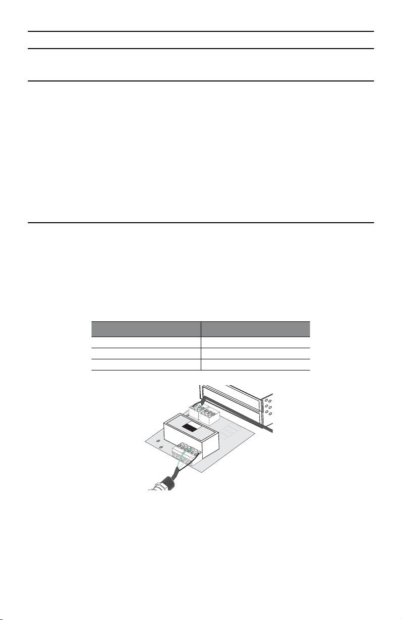
2.2 Connecting the power cable wires to the EnviroNET
To connect the power cable wires to the EnviroNET:
1.
Run the power cable wires from outside of the EnviroNET through the unscrewed gland (on the far left) to
the inside of the unit.
2.
Connect the power cable wires to the external power connection block that is labeled,
in
table 1
.
E N L
, as described
Table 1.
Designated Slot
Power cable wires
Power Wire (Color)
Earth (E) Green
Neutral (N) White
Line (L) Black
ACIN
100-240V
0.15A
50/60Hz
POWER
BLOCK
DCOUT
PWB-5002
12V/0.42A
ENL
3.
Be sure to leave a little slack on the wires so that they are not stressed or pulled too tightly. Also, make
sure that the power cable wires are secured tightly in the
4.
To ensure that the cables are properly secured in the gland, tighten the gland by turning the loose pieces
E N L
block.
all the way to the right using a Crescent® (adjustable) wrench.
EnviroNET Quick Start Guide
3
Page 4

3.0 Wiring the terminal block
3.1 Running the twisted pair wires through the gland
To run the twsited pair wires through the gland:
1.
Locate the glands that the twisted pair wires should run through.
2.
You may unscrew the gland to allow more flexibility when threading the wires. To unscrew the gland,
either by hand or with a Crescent® (adjustable) wrench, turn the gland to the left until it is loosened.
3.
Carefully thread the wires through the gland from the outside into the EnviroNET.
Note
The brass glands on the bottom panel of the EnviroNET can properly seal cables with an outer diameter
between 3mm and 8mm.
3.2 Connecting the twisted pair wires to the EnviroNET
To connect the twisted pair wires to the EnviroNET:
1.
Run the twisted pair wires from outside of the EnviroNET through the unscrewed glands (on the right) to
the inside of the unit.
2.
Connect the appropriate wires to the appropriate slots in the terminal block. There should be one wire per
gland. Follow the wiring diagram that is on the inside of the EnviroNET door. The terminal block is also
labeled with the numbers.
3.
Be sure to leave a little slack on the wires so that they are not stressed or pulled too tightly. Also, make
sure that the twisted pair wires are secured tightly in the terminal block.
4.
To ensure that the cables are properly secured in the gland, tighten the gland by turning the loose pieces
all the way to the right using a Crescent® (adjustable) wrench.
Note
The black plugs for the brass glands on the bottom panel of the EnviroNET
4
should not
be removed.
EnviroNET Quick Start Guide
Page 5

4.0 Configuring the EnviroNET
You can configure the EnviroNET via the dip switches on the PC board (except for the 2156 and 2157 models,
which require no user configuration).
Dip Switch
POWER ONE
BLP-30
S
S
1234ON56 78
1234ON56 78
4.1 EnviroNET Model 2172
EnviroNET Model 2172 uses DIP switch S2 to configure the line rate, symmetric or asymmetric, Ethernet, and
Ethernet Shutdown. Table 2 shows a summary of each switch.
Table 2.
Position
S2 Summary
Description
S2-1 Symmetric/Asymmetric
S2-2 Line Rate
S2-3 Line Rate
S2-4 Ethernet configuration
S2-5 Ethernet configuration
S2-6 Ethernet configuration
S2-7 Ethernet Shutdown Enable
S2-8 Remote Configuration
Switch 1: Symmetric/Asymmetric Operation
To configure the unit for symmetric or asymmetric operation, push the first toggle switch up or down.
Refer to Table 3 for settings.
Table 3.
S2-1 Setting
ON Symmetric Operation
OFF Asymmetric Operation
EnviroNET Quick Start Guide
Symmetric/Asymmetric Operation
5
Page 6

Switches 2 and 3: Data Rate
Refer to
table 4
for the symmetric line rate settings. (Switch 1 must be in the “
Refer to
table 5
for the asymmetric line rate settings. (Switch 1 must be in the “
On”
Off”
position).
position).
Table 4.
OFF ON 50 Mbps
ON OFF 25 Mbps
OFF OFF 10 Mbps
Table 5.
S2-2
ON ON 50 Mbps/2 Mbps
ON OFF 16 Mbps/2 Mbps
OFF OFF 4 Mbps/1 Mbps
Symmetric CopperLink Line Rates Selection Chart
S2-2
S2-3 Symmetric Line Rate
Asymmetric CopperLink Line Rates Selection Chart
S2-3 Asymmetric Line Rates DS/US
Switches 4, 5 and 6: Ethernet Configuration
Refer to
table 6
to configure Ethernet settings with switches 4, 5, and 6.
Table 6.
S2-4 S2-5 S2-6 Ethernet Configurations
ON ON ON Auto-Negotiate
ON ON OFF 100Mb Full Duplex
ON OFF ON 100Mb Half Duplex
ON OFF OFF 10Mb Full Duplex
OFF ON ON 10Mb Half Duplex
Ethernet configurations
Switch 7: Ethernet Shutdown
To enable or disable Ethernet Shutdown, push toggle switch seven (7) up or down.
Refer to
table 7
for settings.
Table 7.
S2-7
ON Ethernet Shutdown Enabled
OFF Ethernet Shutdown Disabled
6
Ethernet Shutdown
Description
EnviroNET Quick Start Guide
Page 7

Switch 8: Remote Configuration
To enable or disable Remote Configuration, push toggle switch eight (8) up or down.
Refer to
table 8
for settings.
Table 8.
S2-8
ON Remote Configuration Enabled
OFF Remote Configuration Disabled
Note
The S2-8 switch applies to the remote unit only. If enabled, the remote unit will follow the dip switch
configuration of the local unit. If disabled, the remote unit will use its own dip switch setting to determine its Ethernet operating mode and Ethernet Shutdown mode configuration. The S2-8 switch does not
affect the data rate. The data rate will always follow the local configuration.
Remote Configuration
Description
4.2 EnviroNET Model 2168
EnviroNET Model 2168 uses DIP switch S1 to configure the line rate, symmetric or asymmetric, Ethernet full auto
negotiation capability or limited auto sense. Table 9 shows a summary of each switch.
Table 9.
Position
S2-1 Ethernet Auto Sense
S2-2 Line Rate
S2-3 Line Rate
S2-4 Line Rate
S2-5 Reserved
S2-6 Reserved
S2-7 Reserved
S2-8 Reserved
S1 Summary
Description
Switch 1: Ethernet Auto Sense
To configure the unit for full auto sense capability or limited auto sense capability, push the first toggle switch up
or down. Full Auto sense capability consists of standard Ethernet Auto sensing (100BaseT full duplex, 100BaseT
half duplex, 10BaseT full duplex, and 10BaseT half duplex). Limited Auto sensing capability consists on only
auto sensing for 100BaseT half duplex, 10BaseT full duplex, and 10BaseT half duplex. The limited auto negotiation feature is used when an Ethernet device does not comply with IEEE 802.3x (back pressure flow control) at
100M full duplex.Refer to
EnviroNET Quick Start Guide
table 10
S1-1
OFF Full Auto Negotiation (Factory Default)
for settings.
Table 10.
(100 Mbps, Full or Half Duplex)
(10 Mbps, Full or Half Duplex)
Ethernet Auto Sense Selection Chart
Setting
7
Page 8

Table 10.
S1-1
ON Limited Auto Negotiation
(100 Mbps Half Duplex)
10 Mbps Full or Half Duplex)
Switches 2, 3, and 4: Data Rate
Refer to
Refer to
table 11
table 12
for the symmetric line rate settings. (Switch 1 must be in the “
for the asymmetric line rate settings.(Switch 1 must be in the “
Ethernet Auto Sense Selection Chart
Setting
On”
Off”
position).
position).
Table 11.
S1-2 S1-3 S1-4 Symmetric Line Rate
ON ON ON 6.25 Mbps
ON ON OFF 9.38 Mbps
ON OFF OFF 12.5 Mbps (Factory Default)
ON OFF ON 16.67 Mbps
Table 12.
S1-2
OFF OFF ON 4.17 Mbps/1.56 Mbps (Mode 0)
OFF ON ON 9.38 Mbps/1.56 Mbps
OFF ON OFF 16.67 Mbps/2.34 Mbps
S1-3 S1-4 Asymmetric Line Rates DS/US
Symmetric CopperLink Line Rates Selection Chart
Asymmetric CopperLink Line Rates Selection Chart
Switches 5, 6, 7, and 8: Reserved
Switches 5, 6, 7, and 8 are reserved and should be in the ‘
Table 13.
S1-5
OFF OFF OFF OFF Reserved (Factory Default)
S1-6 S1-7 S1-8 Reserved
Reserved for future use
Off
’ position.
8
EnviroNET Quick Start Guide
Page 9

5.0 Mounting the EnviroNET
The EnviroNET can be mounted in two ways, wall mount and pole mount.The wall mount is the typical way that
an EnviroNET can be mounted. You will need four bolts to mount the EnviroNET.
To mount the EnviroNET:
1.
Make sure that the location where you chose to mount the EnviroNET is sturdy and can securely hold the
unit.
2.
Be sure that the door to the EnviroNET is securely closed and locked. To lock the case, close the door and
use a flat-tip screwdriver to turn the locks to all the way to the right.
3.
Mount the EnviroNET by securing the bolts through the holes on the EnviroNET to the wall panel.
Note
The pole mount option is available by request. For information on how to mount the EnviroNET to a
pole, refer to the
Pole Mount Kit Quick Start Guide
that shipped with the pole mount kit.
6.0 Operating the EnviroNET
The EnviroNET is designed to be powered on automatically. There is no power switch. The green power LED will
light when the power is on (ET and EC models only).
To power the EnviroNET:
1.
You need to wire the power cable. If you haven’t done this already, go to the section,
power”
on page 3.
2. After all of the cables are properly wired, close and lock the case. Plug the power cable into an electrical
outlet.
2.0 “Wiring the
Note Once in operation, the EnviroNET will run over all temperatures without user intervention.
The EnviroNET ET and EC models have two LEDs, Power and Temperature Control Indicator.
The Power light will be on when the EnviroNET is operating normally.
The Temperature Control Indicator light will be on when the heater or fan turns on to control temperature.
Note EH models do not have a fan or heater, therefore they do not have LEDs.
7.0 Additional Information
Refer to the EnviroNET 2100 Series User Manual located on the CD-ROM shipped with your EnviroNET and available online at www.patton.com/manuals. For detailed information about:
• Installing, configuring, operating, and troubleshooting.
• Warranty, trademark & compliance
EnviroNET Quick Start Guide
9
Page 10

A.0 Customer and Technical Support
Online support: www.patton.com
E-mail support: support@patton.com—answered within 1 business day
Telephone support:
• Standard: +1 (301) 975-1007 (USA), Monday–Friday: 8:00 am to 5:00 pm EST (1300 to
2200 UTC/GMT)
• Alternate: +41 (0)31 985 25 55 (Switzerland), Monday–Friday: 8:00 am to 5:00 pm CET (0900 to 1800
UTC/GMT)
Fax: +1 (253) 663-5693 (USA) or +41 (0)31 985 25 26 (Switzerland)
B.0 Compliance Information
B.1 Compliance
EMC Compliance:
• FCC Part 15, Class A
• EN55022, Class A
• EN6100-6-2
Safety Compliance:
• UL60950-1/CSA C22.2 No. 60950-1
• IEC/EN 60950-1
• AS/NZS 60950-1
PSTN Regulatory Compliance:
Note This device is NOT intended nor approved for connection to the PSTN.
It is intended only for direct connection to customer premise equipment.
10 EnviroNET Quick Start Guide
Page 11

B.2 Radio and TV Interference (FCC Part 15)
This equipment generates and uses radio frequency energy, and if not installed and used properly—that is, in
strict accordance with the manufacturer's instructions—may cause interference to radio and television reception. This equipment has been tested and found to comply with the limits for a Class A computing device in accordance with the specifications in Subpart B of Part 15 of FCC rules, which are designed to provide reasonable
protection from such interference in a commercial installation. However, there is no guarantee that interference
will not occur in a particular installation. If the equipment causes interference to radio or television reception,
which can be determined by disconnecting the cables, try to correct the interference by one or more of the following measures: moving the computing equipment away from the receiver, re-orienting the receiving antenna,
and/or plugging the receiving equipment into a different AC outlet (such that the computing equipment and
receiver are on different branches).
B.3 CE Declaration of Conformity
We certify that the apparatus identified in this document conforms to the requirements of Council Directive 89/
336/EEC, as amended by Directives 92/31/EEC and 93/68/EEC on the approximation of the laws of the member states relating to electromagnetic compatibility; and Council Directive 73/23/EEC, as amended by Directive
93/68/EEC, on the approximation of the laws of the member states relating to electrical equipment designed for
use within certain voltage limits.
The safety advice in the documentation accompanying this product shall be obeyed. The conformity to the above
directive is indicated by the CE sign on the device
B.4 Authorized European Representative
D R M Green, European Compliance Services Limited.
Oakdene House, Oak Road , Watchfield, Swindon, Wilts SN6 8TD, UK
Page 12

Copyright statement
Copyright © 2007, Patton Electronics Company. All rights reserved.
The information in this document is subject to change without notice. Patton Electronics assumes no
liability for errors that may appear in this document.
Trademarks statement
The term EnviroNET is a trademark of Patton Electronics Company. All other trademarks presented in this docu-
ment are the property of their respective owners.
Warranty, Trademark, & Compliance Information
For warranty, trademark and compliance information, refer to the EnviroNET 2100 Series User Manual located on
the CD-ROM that came with your EnviroNET or available online at www.patton.com.
• This device is to be installed only by qualified service personnel. It contains no user serviceable
parts, and shall be returned to Patton Electronics for repairs, or repaired by qualified service personnel.
WARNING
• Hazardous network voltages are present in WAN ports regardless of whether power to the unit is
ON or OFF. To avoid electric shock, use caution when near WAN ports. When detaching the cables,
detach the end away from the device first.
• Do not work on the system or connect or disconnect cables during periods of lightning activity.
• This device is NOT intended nor approved for connection to the PSTN. It is intended only for connection to customer premise equipment.
In accordance with the requirements of council directive 2002/96/EC on Waste of Electrical and Electronic Equipment (WEEE), ensure that at end-of-life you separate this product from other waste and
scrap and deliver to the WEEE collection system in your country for recycling.
12 EnviroNET Quick Start Guide
 Loading...